
Abstract
In microelectronics manufacturing, macro–micro actuation stages are typically applied to obtain a high-precision positioning at a high acceleration. Macro–micro actuation stage comprises a voice coil motor that achieves a high-acceleration motion and a piezoelectric stack actuator which realizes nano-positioning motion. However, high acceleration and nano-positioning are a pair of interacted contradictions. Especially, vibration generated from the high-acceleration motion is the dominating obstacle for enhancement of the nano-positioning implementation. The concentration of the article is a design of a linear macro–micro actuation stage considering vibration isolation. In particular, a floating stator system is proposed to suppress the stage’s vibration and further guarantee a higher precision positioning. Additionally, a flexure hinge mechanism connected to the voice coil motor serially is proposed to achieve a linear motion guide and preload to the piezoelectric stack actuator. The results show that the isolate vibration of the floating stator system is effective in both the time and frequency domain analysis of test. And precision positioning is also further validated experimentally through the flexure hinge mechanism and other components.
Keywords
Introduction
With the rapid development of technology and dramatically increasing demand of market, the fields of microelectronic manufacturing engineering, optical engineering, precision engineering, nano-scale science, and so on1–3 urgently call for a stage to accomplish high-acceleration and nano-positioning motion in a long stroke (at the centimeter level).4–6 However, there is a contradiction between high acceleration and nano-precision positioning. When high acceleration is obtained, the high positioning accuracy is inevitably limited. Similarly, when the high positioning accuracy is achieved, the movement space could not be easily supplied to meet a long motion stroke demand.
The contradiction between high acceleration and nano-precision positioning cannot be resolved until the development of a macro–micro actuation stage concept comprising voice coil motor (VCM) and piezoelectric stack actuator (PSA). 7 In the stage, VCM is a macro actuator to provide a high acceleration and a long motion stroke, and PSA is a micro actuator to accomplish error compensation and nano-positioning motion. The macro–micro actuation stage concept is developed in a variety of applications as follows: in the computer hard disk drive (HDD) industry, the macro–micro actuation stage concept is practiced to increase the storage density of an HDD system. A VCM generally provides an adequate motion stroke, while the PSA compensates for the errors of VCM and increases the servo bandwidth and precision of such a servo system.8–12 The macro–micro stage concept is also practiced in macro–micro robot applications.13–15 A micro robot is fixed on a macro robot to obtain an adequate space while the micro robot achieves high-precision position. There are much more concentrations on the macro–micro actuation in precision positioning system. Dong et al. 3 reported a macro–micro actuation stage consisting of a VCM and a PSA. The preliminary closed-loop experiment showed that the piezoelectric actuator could compensate the error of the VCM and the system precision was improved from 200 to 20 nm. Liu et al. 16 developed a high-precision stage comprising a VCM and a PSA which achieved a positioning accuracy of 10 nm. Elfizy et al. 17 proposed a macro–micro actuation stage for milling. In sinusoidal profile cutting experiments, the maximum tracking error was reduced by 83% and the average magnitude of the error was reduced by 63%. Zhang et al. 18 established a macro–micro actuation stage through a structure model with macro–micro concept. Similarly, Tong et al. 19 utilized a linear motor and a magnetostrictive actuator for macro–micro actuation stage control. Kwon et al. 20 developed a macro–micro dual-stage manipulator for micro-tele-operation, in which an XY fine stage was mounted on a two-dimensional (2D) macro positioner. Kim et al. 21 proposed a macro–micro actuation research application on cam machining, which integrated together an electro-hydraulic actuator with a 25-mm gross motion and a piezoelectric actuator with a 40-μm micro motion.
In the macro–micro actuation stage, the contradiction between high acceleration and nano-positioning could be solved. Yet, vibration from high acceleration is the dominating obstacle for further improvement of nano-positioning. Therefore, the design of a linear macro–micro actuation stage considering vibration isolation is investigated in the article. First, the design objective is presented. And then, in order to prevent the realization of precision positioning from vibration influence, a floating stator system is designed to explore its vibration suppressing. Moreover, a flexure fixture is developed as the connection mechanism to maintain the motion stroke of the PSA. Finally, the effectiveness of the developed stage is testified by experiments.
Macro–micro actuation stage design considering vibration isolation
Design objective
In the article, a macro–micro actuation stage is developed to simultaneously provide a high-acceleration motion in a long motion stroke of centimeter level and nano-positioning for precision positioning motion. It is achieved by an integration of a PSA (fine actuator) and a VCM (coarse actuator). That is, the stroke of the PSA will compensate the motion errors of the VCM. Moreover, the PSA with high bandwidth can cover system errors. The stage is supposed to provide a continuous stall force particularly in motion direction. In order to reduce the effect of an external disturbance under operating conditions, a floating stator system is employed to absorb the external disturbance. The driving frequency of VCM is 1000 Hz. In order to avoid system resonance, the natural frequency of the structural components should be more than 1000 Hz. 3
A three-dimensional (3D) solid model of the macro–micro actuation stage is proposed as shown in Figure 1(a). Its related configuration is described as follows: a rectangular VCM is employed as macro actuator. The VCM connects base through floating stator system including damper, stopper, limiter, spring, and so on. The stopper fixed on VCM limits the movement range with the help of limiter and spring. The output coil of the motor is connected to one end plane of the connection frame which is supported by the linear guides based on the supporting platform. The other end plane of the connection frame is connected to a macro actuation stage which is supported by the linear guides based on the supporting platform, as shown in Figure 1(b). A PSA is housed in macro actuation stage under preload and micro actuation stage is fixed on macro actuation stage by flexure hinge mechanism. A coarse grating ruler is installed on the side of macro actuation stage and is read by a grating ruler reading head fixed on the supporting platform. The other fine grating ruler is installed on the plane below the micro actuation stage and the grating ruler reading head is fixed on the supporting platform, as shown in Figure 1(c). In the stage, the VCM actuator pushes macro actuation stage through connection frame to realize a long stroke, high acceleration, and speed, and the PSA induces a compensation motion relative to the macro actuation stage. As suggested by previous studies, 22 a floating stator system can effectively reduce the stage’s suppressing vibration and guarantee a higher precision positioning. It is also important that a vital module in the design is the flexure hinge mechanism between macro and micro actuation stage which houses the PSA. To obtain a preload and linear motion guide, four two-axis parallel flexure hinges are employed to realize a seamless connection between the PSA and the micro actuation stage.

Design overview of the (a) macro–micro actuation stage, (b) floating stator system, and (c) perspective drawing of fine grating ruler.
Floating stator system analysis
During the working of macro–micro actuation stage, VCM provides a driving force to achieve a high acceleration in a short time while there is a reactive force that has a huge impact force on the stator of VCM. If the stator is fixed on the base, the impact force inevitably induces the vibration of base. 22 Since high positioning accuracy is difficult to be obtained on severe vibration platform, floating stator system is employed to suppress the stage’s vibration.
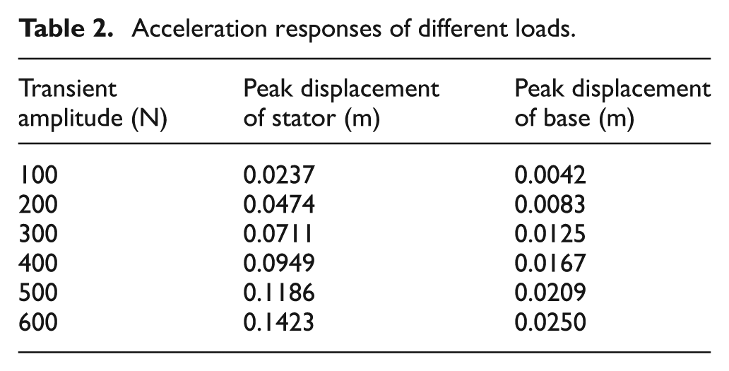
The connection between base and ground is equivalent to a spring–damp system. Similarly, a floating stator system is recognized as a spring–damp system to be installed between the stator and sub-base which is fixed on the base, as shown in Figure 2. K2 and C2 are essentially equivalent stiffness coefficient and damping coefficient of the floating stator system, respectively. Finite element model of the floating stator system has been built in ANSYS12.1. The stator, base, and ground are built as three mass nodes with MASS21. The above spring–damp systems are built as spring element and damp element with COMBIN14. A transient exciting force signal is applied on stator. Transient dynamic analysis of the floating stator system is performed. The change trends of peak displacement of base and stator are obtained as follows: the peak displacement of stator decreases with K2. The peak displacement of base increases first and then decreases with K2. The peak displacement of stator decreases with C2. The peak displacement of base increases and decreases with C2, as shown in Figure 3. In the research, the reference values of kinetic parameters of macro–micro actuation stage are selected, as shown in Table 1. The finite element simulation results report that the displacement vibration of base significantly reduces compared with that of VCM, as shown in Figure 4. Moreover, as the exciting force value increases, the displacement response of stator would correspondingly increase, but suppression is higher for larger force, as shown in Table 2. The above observations indicate that the floating stator system could achieve vibration suppressing effect.

Schematic of floating stator system.
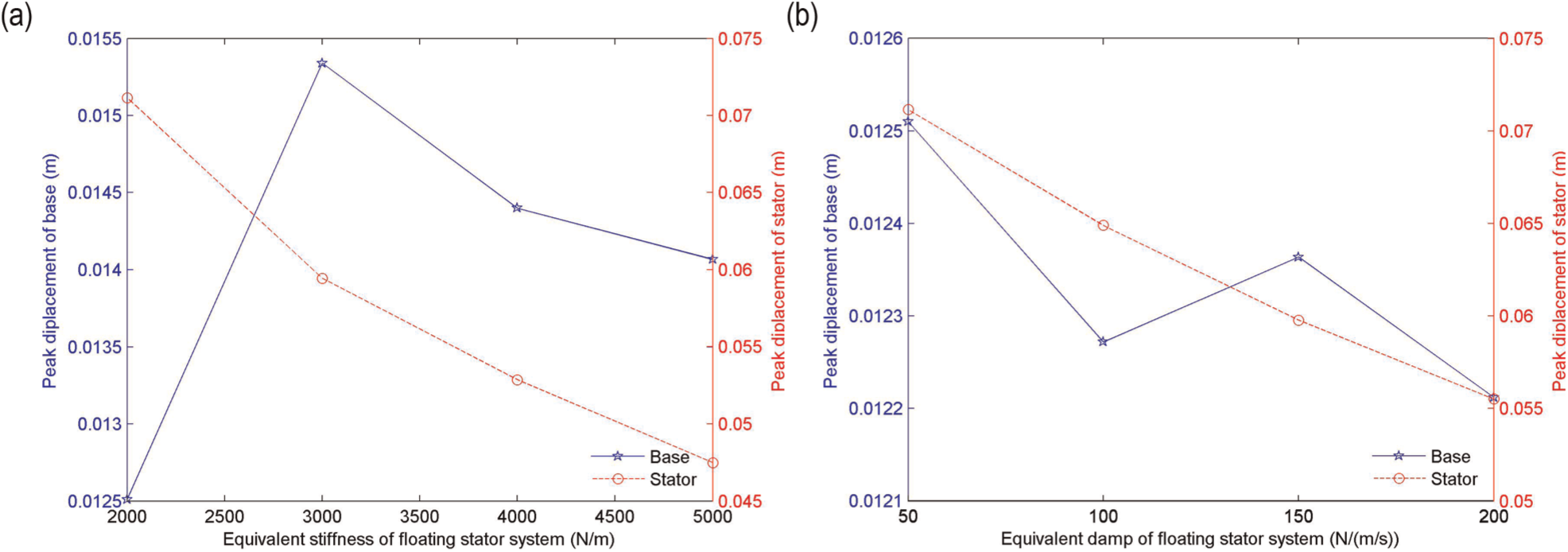
Change trend of peak displacement of base and stator with (a) K2 and (b) C2.
Reference values of kinetic parameters of macro–micro actuation stage.

Acceleration responses of different loads.

Transient displacement response.
Flexure mechanism analysis
A low-voltage PSA (P-845.20), which has a 30-μm motion stroke and a 3000-N output force, is adopted as a micro actuation stage actuator. Actually, the actuator’s bandwidth is decided by the motion magnitude. The PSA’s motion stroke and its actuation bandwidth have to be effectively applied.
In order to make the best of the PSA’s motion stroke and its actuation bandwidth, a flexure hinge mechanism is proposed to achieve a minimized loss of positioning stroke and keeping stiffness in all directions. The flexible platform has macro actuator, micro actuator, and four same two-axis parallel flexure hinges, as shown in Figure 5. This type of flexure hinge can provide 1 degree-of-freedom motion guide. Particularly, this design can minimize the deformation in the non-motion directions during the machining process. Usually, micro motion platform is used to support the microelectronic device to accomplish the device’s precision position in high acceleration and speed. Although the device’s mass is so light that it cannot affect deformation of the flexure hinges, it should be considered that the flexure hinges are subjected to the influence of high acceleration and speed in Z-direction, which is controlled in linear motion by the macro–micro motion stage actuation, as shown in Figure 6. However, the X-axis and Y-axis influence is not subjected to active control. Therefore, high stiffness is needed to resist the high-acceleration disturbance in these two directions. Additionally, high acceleration can also induce possible deformations of Z–Y twisting and Z–X torsion. These unknown deformations would reduce the final position precision. It also leads to unqualified component product and further resource waste.

Flexure hinge illustration with two-axis parallel flexure hinges.

Working condition analysis of flexure hinge.
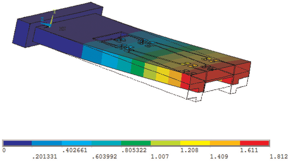
Based on the above discussions, a layout with two-axis parallel flexure hinges is adopted to increase the linear and torsional stiffness in the aforementioned non-motion directions. The finite element model of flexure hinge mechanism is built in ANSYS to implement simulation analysis. The reference value of the material properties of flexible platform is shown in Table 3. First, static deformation of the whole flexure hinge mechanism is calculated in high acceleration. The results indicate that the deformation is limited to the flexure hinge part with the current flexure hinge design, while the housing part does not have significant deformation, as shown in Figure 7. The stiffness in X-axis direction is calculated as 37.78 N/μm, which means that the motion stroke in linear motion direction can be preserved at ∼79.4 μm approximately. The practical motion stroke relies on the preload and the output force of the PSA in operating conditions. It can be measured by later experimental testing.
Reference value of key geometric and material properties of flexible platform.


Static finite element analysis result.
The vibration suppression of the flexible platform for different load conditions is further studied. The flexible platform comprising two-axis parallel flexure hinges model is subjected to normal mode analysis, transient load analysis, and frequency response analysis to demonstrate the response of two-axis parallel flexure hinges for different acceleration, velocity, and displacement. Acceleration responses were picked up at the appropriate node 656 and 643 locations indicated in Figure 8. The goal of the model is to demonstrate the effect of two-axis parallel flexure hinges on vibration transmission and is used to fine adjust vibration isolator design. The simplified 3D model of the flexible platform built in Solid Works was directly imported into ANSYS 12.1 for finite element model. Key geometric dimensions of two-axis parallel flexure hinges were taken as given in Table 3. The hole distance of a two-axis parallel flexure hinges is 6.5 mm width and the hole radius is 3.5 mm. The vertical hole distance is 32.5 mm and the horizontal is 76.5 mm. The thickness of micro actuation stage is 14 mm. The two-axis parallel flexure hinges are placed symmetrically with respect to neutral axis of the horizontal beam and these are at 16.25 mm from the neutral axis. The material of the whole flexible platform is duralumin. For modeling, 3D solid 45 element was used for the whole flexible platform. Analysis was performed for both static and dynamic load cases.
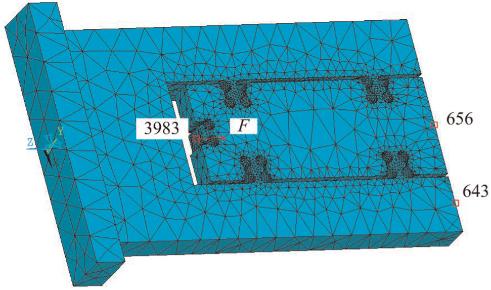
Node details on finite element model of the flexible platform.
Normal mode analysis
The frequencies and mode shapes of the flexible platform comprising four two-axis parallel flexure hinges were obtained by finite element method. The first frequency of flexible platform is 379 Hz and its mode shape moves up and down in the right of macro and micro actuation stage, as shown in Figure 9. Other frequencies and mode shapes of flexible platform comprising two-axis parallel flexure hinges are shown in Table 4.
First mode of the flexible platform.
First five vibration frequencies and modes.

Transient response analysis
The flexible platform can achieve high acceleration through VCM driving macro actuator connection. To demonstrate that there is a vibration isolation across the two-axis parallel flexure hinges for any load applied at the flexible platform, dynamic analysis of the flexible platform was carried out. The loads are equivalent to varying accelerations. For the varying accelerations applied in the flexible platform along Z-direction, the nodal response of points 643 and 656 was analyzed. When the flexible platform was applied on an acceleration of 1 g (m/s2), the transient response of points 643 and 656 measured was as plotted in Figure 10(a) and (b), respectively. Table 5 shows the response variation across the two-axis parallel flexure hinges for varying accelerations. It can be noted that the higher accelerations are obtained at point 643 and acceleration is low at point 656. With the increase in the load, there is a corresponding increase in the acceleration. However, suppression is higher for higher loads. It is also observed that when loads on the flexible platform are higher, better isolation could be obtained.
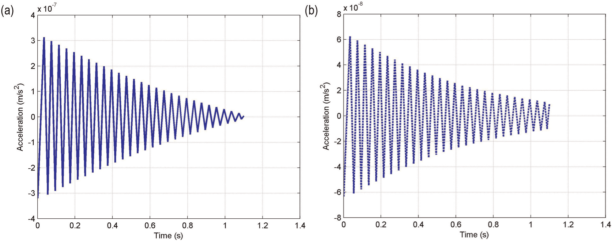
Transient acceleration responses of points (a) 643 and (b) 656.
Acceleration responses of different loads.

Frequency response analysis
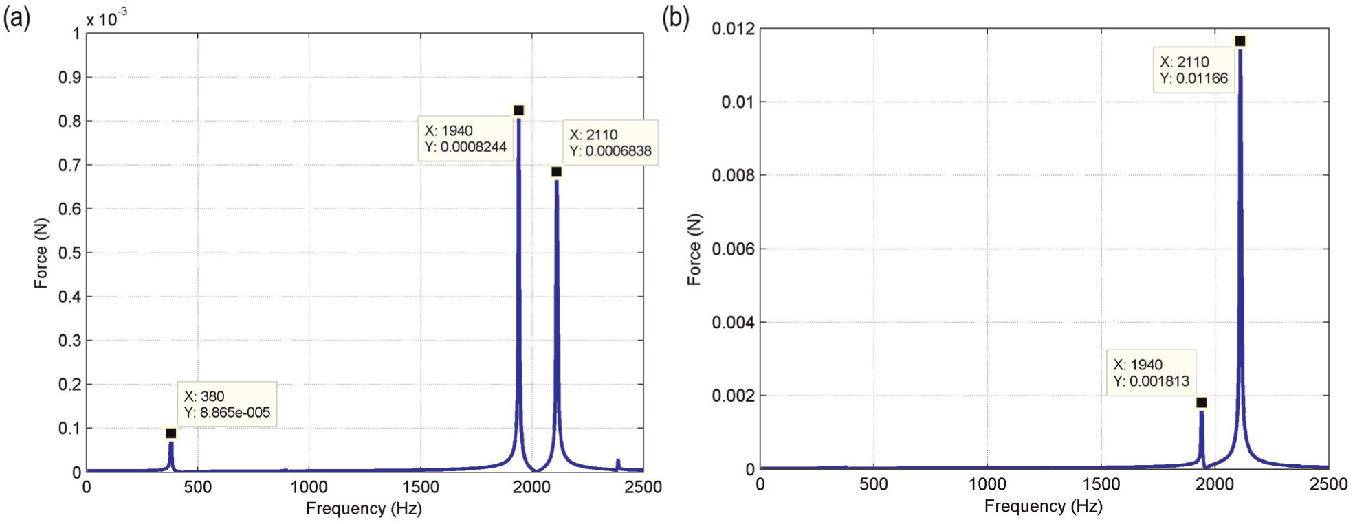
In order to characterize the behavior of the flexible platform at different frequencies, the flexible platform was subjected to frequency response analysis. An input load of 1000 N with frequency varying from 0 to 2500 Hz was applied on point 3893 as shown in Figure 8. The responses were taken at points 643 and 656. The first peak response occurred at the first mode of 380 Hz. The response that was 8.865 × 10⁻⁵ m/s2 at point 643 as shown in Figure 11(a) reduced to 0 m/s2 as shown in Figure 11(b). These two responses were 8.244 × 10⁻⁴ and 6.838 × 10⁻⁴ m/s2 at point 643 as shown in Figure 11(a) and increased to 1.813 × 10⁻³ and 1.186 × 10⁻² m/s2 at point 656 as shown in Figure 11(b). However, the driving frequency of flexible platform is less than 1000 Hz which can avoid resonance with other bodies. The above observations indicate that flexible platform is able to reduce or avoid response corresponding to all resonance states.
Frequency responses of points (a) 643 and (b) 656.
Prototype system
Based on the above work, a macro–micro actuation stage prototype considering vibration isolation is fabricated, as shown in Figure 12. The flexible platform with two-axis parallel flexure hinges is realized by electrical discharge machining (EDM) technique. A rectangular VCM made by us is used as the macro actuation stage actuator to provide a 450-N continuous stall force and an 80-mm motion stroke. In the macro–micro actuation stage, three linear motion guide stages are comprised of NV 3150-29z (Futai Co.), MR9WNSS2VON-170-10-10II (Futai Co.) and MR9WNSS2VON-170-10-10II (Futai Co.), respectively. The first one is used between macro actuation stage and the supporting platform. The second one is applied between the sub-base and stator, and the last one is installed between connection frame and supporting platform. In floating stator system, a damper KSHA6*8C-F (KOGANEI Company) is installed in the limiter. A low-voltage PSA P-845.20 driven by an E-621 (PI Inc.) is employed as the micro stage actuator. Linear grating ruler system (HEIDENHAIN Company) is used to measure the macro and micro motion displacement. Two same glass rulers (L2F 401R Glass Scale ML 120 mm), as measuring standard, are read by two grating ruler reading heads (LIF 47R-20 FOLD and LIF 47R-100 FOLF) which can provide 50 and 10 nm resolution, respectively, when a subdivision unit is connected between the sensor read head and the data acquisition board. And then, compensating errors between macro and micro actuation position as well as nano-scale position can be obtained by the two grating ruler reading heads. According to the errors, P-845.20 with resistance strain gauge sensor can make up for the errors through driving E-621.

Macro–micro actuation stage prototype.
Experiment analysis
Base on the above discussion, the numerical simulation results indicate that the floating stator system can suppress the stage’s vibration. There is another concentration on the design of the flexure hinge mechanism between macro and micro actuation stage which houses the PSA. Dynamic finite element analyses of flexure hinge mechanism prove that it is feasible to employ four two-axis parallel flexure hinges to realize a seamless connection between the PSA and the micro actuation stage under a preload. In this research, the vibration suppressing effect could be further validated experimentally, which would help to guarantee a higher precision positioning. Based on the floating stator system, we essentially focus on obtaining a precision positioning through the flexure hinge mechanism and other components.
Vibration experiment
Figure 13 shows an illustration of the floating stator’s vibration measurement system. When macro–micro actuation stage provides a driving force to realize a high acceleration of VCM output, the same reactive value but inverse is applied on the stator. The macro–micro actuation stage is installed on the vibration isolation platform. Data acquisition system is used to collect data from measured points of stator and base, as shown in Figure 14. These data are transmitted and analyzed in MATLAB.

Illustration of the vibration measurement system.

Measured points of stator and base of floating stator system.
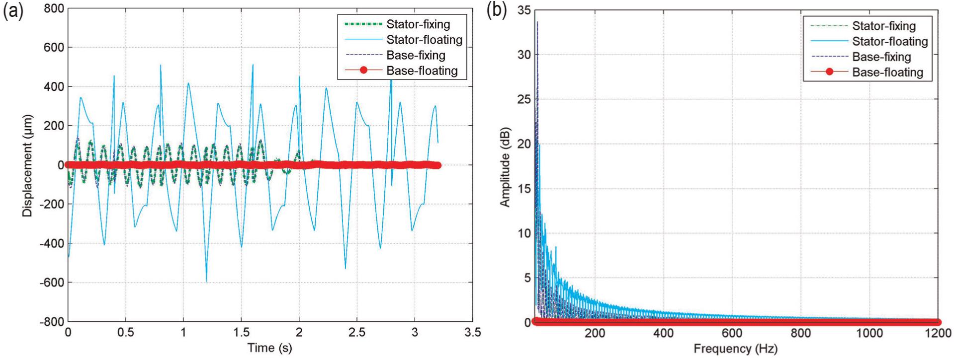
In order to verify vibration suppressing and damping effectiveness of the floating stator system in linear motion, the vibration measurement of a fixing stator system is also accomplished under the same condition. The vibration data of stator and base in linear motion are collected and recorded in floating and fixing stator systems. These data are processed by MATLAB to obtain frequency domain and time domain consistently with varying acceleration, velocity, and displacement. The results indicate that vibration accelerations of the base and stator in floating stator system have availably reduced compared with that in fixing stator system, as shown in Figure 15(a). Due to the floating stator system, the peak frequency amplitude is relatively stable, and frequency concentration is eliminated on a domain between 400 and 500 Hz in the fixing stator system, as shown in Figure 15(b). It is in accordance with Wang and Li. 22 Similarly, vibration velocity and displacement of base in floating stator system have also evidently reduced compared with that in fixing stator system, as shown in Figures 16(a) and 17(a), respectively. In floating stator system, vibration velocity of the stator is slightly increased, and vibration displacement of stator significantly increases. It is because that the velocity and displacement vibration of base can be essentially reduced by increasing those of stator in floating stator system. Therefore, the velocity and displacement vibration of stator in floating stator system are larger than those in fixing stator system. The peak frequency concentration in the floating stator system is also eliminated on a domain between 400 and 500 Hz, as well as 0 and 80 Hz in fixing stator system, as shown in Figures 16(b) and 17(b), respectively.
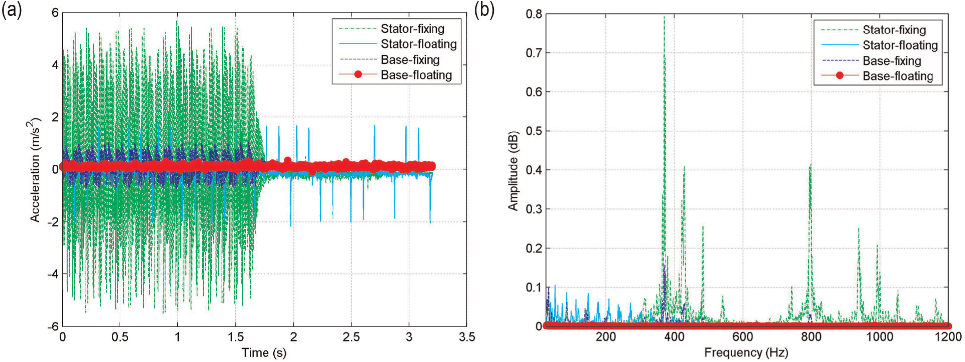
Comparison of acceleration vibration between floating stator system and fixing stator system: (a) time domain comparison and (b) frequency domain comparison.
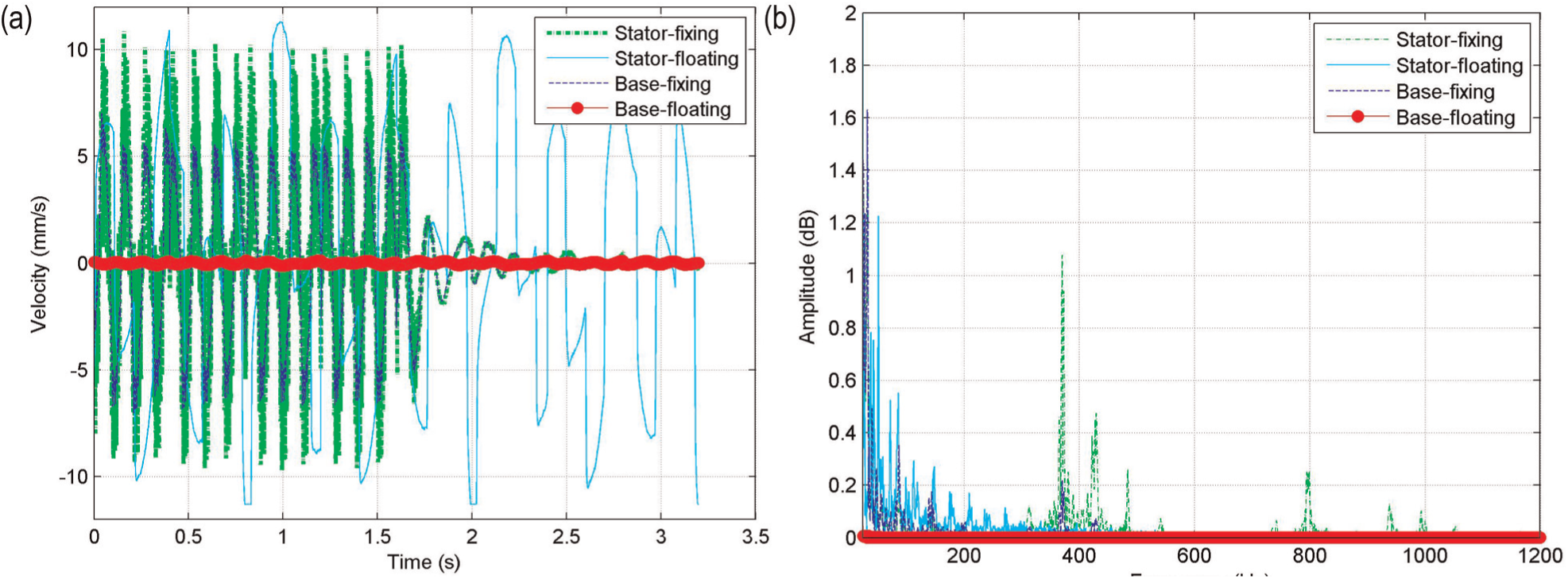
Comparison of velocity vibration between floating stator system and fixing stator system: (a) time domain comparison and (b) frequency domain comparison.
Comparison of displacement vibration between floating stator system and fixing stator system: (a) time domain comparison and (b) frequency domain comparison.
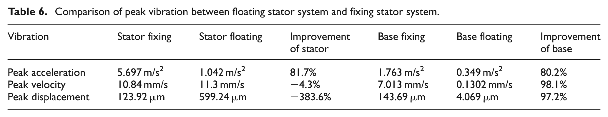
Table 6 further indicates the comparison of vibration peak values between floating stator system and fixing stator system. The peak values of acceleration vibration of base and stator are, respectively, from 1.763 and 5.697 m/s2 in fixing stator system to 0.349 and 1.042 m/s2 in floating stator system. Their improvements are, respectively, 80.2% and 81.7%. Similarly, the peak values of velocity and displacement vibration of base are 7.013 mm/s and 143.691 μm in fixing stator system which reduce to 0.1302 mm/s and 4.0686 μm, with the improvement being 98.1% and 97.2%, respectively, in floating stator system. In order to realize the stability of base, the floating stator increases its velocity and displacement vibration. That is, the peak value of velocity vibration of stator in fixing stator system increases from 10.841 to 11.303 mm/s with the improvement of 4.3% and the peak value of displacement vibration of stator also increases from 123.918 to 599.238 μm with the improvement of 383.6%.
Comparison of peak vibration between floating stator system and fixing stator system.
Precision positioning analysis
Based on the vibration suppressing and damping effectiveness verification of floating stator system in linear motion, a precision positioning is also further validated experimentally through the flexure hinge mechanism and other components as follows. The precision positioning experiment is first performed separately on macro actuation positioning which is driven by VCM with no motion of the PSA and micro actuation positioning which is driven by PSA with no input to the VCM. And then, it is accomplished on macro–micro actuation positioning which is jointly driven by VCM and PSA.
For the macro actuation positioning, a 10-mm step of planning position is carried out. The experimental result is shown in Figure 18. Actual position obtained is 9.98 mm. Their error is 20 μm which can be compensated by PSA. And then, the PSA housed in the flexure mechanism is investigated. A 5-μm step of planning position is also implemented. The result indicates that the PSA has a settling time of 15 ms, as shown in Figure 19(a). Due to the high resolution of the PSA, the PSA can be used to compensate the positioning error of the VCM. The final positioning performance of the macro–micro actuation stage is affected by the resolution directly. The method proposed in Lobontiu 23 is used to study the actuation resolution. A range of stepwise inputs are applied to the PSA. The results show that the stepwise input is followed by the output displacement. And its average resolution is superior to 10 nm, as shown in Figure 19(b). It can be concluded that the micro actuation stage can surely achieve a high resolution. Moreover, the maximum motion stroke (79.4 μm) of the PSA is also measured.

Macro actuation positioning error.

Micro actuation positioning error: (a) under step input and (b) under stepwise input.
In order to explore the potential of the macro–micro actuation stage concept and its new design structure, the step tracking performance of the macro–micro actuation stage is finally investigated. In particular, to examine the macro–micro actuation effect, a 5-μm step response is selected as the reference. When the stage is driven by VCM alone, the positioning error is about 200 nm. It means the PSA should provide high bandwidth to compensate for the error. And the positioning error is significantly 20 nm, as shown in Figure 20. The precision position research is fundamental and there is abundant space on performance to improve. The superiority of the macro–micro actuation stage studied by the above investigations has declared large potential in the future study.
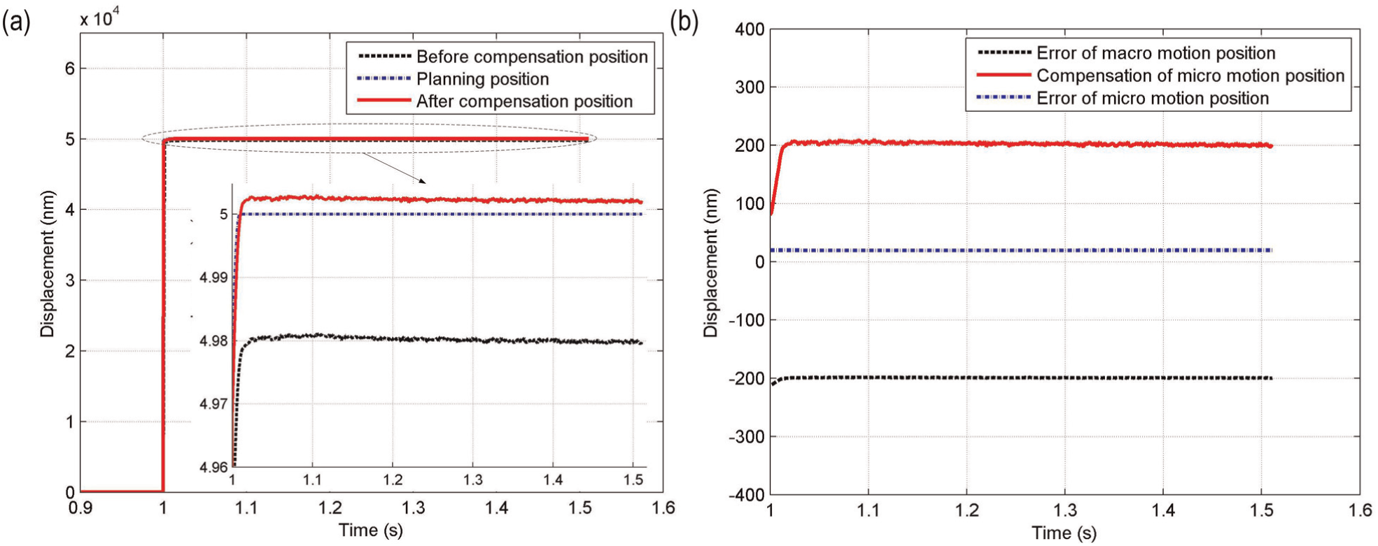
Macro–micro actuation analysis: (a) positioning analysis and (b) error compensation analysis.
Concluding remarks
In the article, a macro–micro actuation stage is developed. It consists of a VCM and a PSA for high acceleration and high precision in a long stroke. Additionally, a mechanism based on two-axis parallel flexure hinges is designed to achieve a linear motion guide and preload to the PSA. In particular, a floating stator system is designed to suppress the stage’s vibration. The relevant numerical and experimental researches are accomplished to facilitate the stage design. And the floating stator system could achieve vibration suppressing effect. The preliminary positioning experiment, using the macro–micro actuation stage prototype, shows that the PSA can improve the system precision from 200 to 20 nm, which could relatively improve system performance. Future work would focus on a macro–micro switching controller design that considers complicated conditions of system.
Footnotes
Academic Editor: Xiaotun Qiu
Declaration of conflicting interests
The authors declare that there is no conflict of interest.
Funding
This work was supported by the Guangdong Key Project (2011A080801004), the Key Joint Project of National Natural Science Foundation of China (U1134004), the Basic Research Plan of Shenzhen (JC201105160586A, JCYJ20120613145622592), the Province University–Industry Cooperation Project (2012B091100022), and the Dongguan City Project in Colleges and Universities (2012108102023).