
Abstract
Traditional material-joining techniques are facing enormous challenges due to the wide use of new materials in engineering. Therefore, the application of bonding technique in engineering becomes more and more important. In order to facilitate designers evaluating the joint strength of bonding structure, a fast and simple strength evaluation method which can be easily used for adhesive joints under complex working conditions was proposed in this article. The normal and shear stresses of the adhesive interface were selected as the main research objects in the method considering the complex working conditions that many bonding structures may face in engineering. Butt joint, single lap joint, and several groups of scarf joint specimens with different adhesive angles were fabricated. Numerous repetitive tensile tests were conducted to obtain the adhesive failure stresses under different conditions. The adhesive failure stress envelope was fitted based on the experimental data, and the evaluation method of adhesive joint strength was developed in detail. Finally, verification experiments were designed. The results indicate that the evaluation method of adhesive joint strength based on the normal–shear stress of the adhesive interface is simple and effective in engineering application.
Keywords
Introduction
In recent years, with the wide use of new materials in engineering structures, such as various alloys, polymers, and composite materials, traditional material-joining techniques such as welding and riveting are facing enormous challenges, as they cannot achieve interconnections of new materials or cannot meet the strength requirements of material joints. In this case, bonding techniques are gaining more and more attention and favor from many researchers and engineers.1–3 The technique possesses several advantages compared with bolt and rivet connection, including widely used materials, dissimilar material connections, neat appearance, and weight reduction.4–8
However, the current status of the adhesive application in engineering is that the adhesives are mainly limited to noncritical secondary structures. In the manufacture of automobiles, the adhesives are almost always used as basic sealant materials or in noncritical secondary structures such as window glass sealing and interior materials bonding. In the manufacture of aircrafts, the use of adhesive-bonded joints has also largely been limited to secondary noncritical structures such as aerodynamic fairings and wing panels. 9 One main reason for this limitation is the lack of a fast and simple evaluation method of adhesive joint strength in engineering. 10 Therefore, the evaluation method of adhesive joint strength has become the focus of a considerable amount of investigations.
There are some methods to study the failure behavior of the adhesive joint, such as stress analysis models,11–13 cohesive zone models,14–17 continuum damage mechanics,17–19 and mixed-mode fracture20–22-based models. Among these research methods, the stress analysis method is one of the very crucial methods. 23 In addition, the stress analysis method has some advantages compared with other methods, being fast, simple, and easy to use. The method is suitable for the adhesive joints under complex working conditions and can be easily understood and applied by the engineers.
There are several criteria which mainly take account of the hydrostatic stress component described in the literature, such as the Drucker–Prager,24–26 the Raghava,27–29 and the Dolev and Ishai criteria. 30 Currently, these criteria are mainly used in the basic theoretical research aspects of adhesive joints, such as the research of adhesive joint yield locus and 25 the prediction of the adhesive strength and ductility in shear from the results in tension. 30 These criteria are difficult for the engineering designers since the criteria have involved a lot of unknown parameters in their derivation process. Therefore, there are still some difficulties for the application of these criteria in the engineering design phase. In addition, some scholars use von Mises criterion31–33 to roughly predict the adhesive joint strength, but it is not strictly valid for polymers. 30
Single lap joints (SLJs) were often used to study the lap shear strength of adhesive joints. Butt joints (BJs) also occasionally appeared in some literatures on the research of tensile strength. However, the fact is that adhesive joints existing in engineering bonding structures do not just withstand single tensile or shear loads. In most cases, adhesive joints are under conditions of both tensile and shear loads. Therefore, an evaluation method of adhesive joint strength which contains both tensile and shear stresses is meaningful for engineering application. Many scholars have done very detailed studies on the stress distribution along the adhesive layer and have got some consensus conclusions: edge effects exist in the stress distribution of the adhesive and the stress distribution is uneven along the adhesive layer.34–36 However, the stress distribution law is difficult to be directly applied to evaluate the adhesive joint strength in engineering since it is very complex. In order to solve this problem, the stress distribution is very necessary to be simplified. In this article, the stress distribution in the adhesive layer is assumed to be uniform and edge effects are ignored. This way, the adhesive failure stress is equal to the average stress of the adhesive layer. This value must be less than the maximum stress occurring in the adhesive layer which leads to the adhesive failure. Therefore, the simplifications and assumptions of the stress distribution in the adhesive layer tend to be safe and conform to the safety design concept in engineering.
In this article, BJs, SLJs, and scarf joints (SJs) with different adhesive angles were fabricated and tested. The ratio of normal and shear stresses (RNS) of adhesive joints was proposed in order to facilitate the application of the method of evaluation of adhesive joint strength. A failure stress envelope which covers all RNS stress states was fitted according to the experimental data. On the basis of this, the method of evaluation of adhesive joint strength in engineering was developed in detail. Finally, a local bonding structure taken from the CRH3 high-speed train (Tangshan, China) was selected as the verification model to verify the effectiveness and reliability of the evaluation method of adhesive joint strength.
Experimental test and stress analysis
Materials selected
The adhesive of the specimens in this article is Sikaflex-265 (SIKA Corp., Sarnen, Switzerland), a one-component polyurethane adhesive for windows which is widely used in passenger cars, trucks, and trains. It was cured to a permanent elastic material by reacting with atmospheric moisture. The adherend was a 6005A aluminum alloy, a material widely used in windows and body structures of automobiles. Table 1 shows the basic material properties of Sikaflex-265 and 6005A aluminum (data provided by supplier).
Material properties of Sikaflex-265 and 6005A aluminum.

Specimen manufacture
The BJ specimens were designed to study the adhesive tensile failure stress, the corresponding RNS was
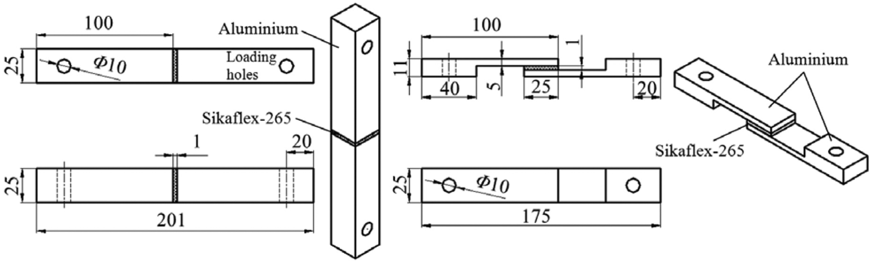
Geometries and dimensions of the BJ (left) and SLJ (right) specimens (dimensions in mm).

Geometries and dimensions of the SJ specimens with the adhesive angle α (dimensions in mm).
Specimen preparation
All of the adhesive specimens were prepared in a clean and stable environment (temperature: 25°C ± 3°C; relative humidity: 50% ± 5%). The preparation process was performed as follows:
The aluminum adhesive surface was wiped by using Sika Remover-208 and dried for 10 min.
The aluminum adhesive surface was abraded along the 45° direction with sandpaper.
The abraded aluminum adhesive surface was wiped again with Sika Remover-208 and dried for 10 min.
The aluminum adhesive surface was wiped along a single direction using Sika Aktivator and dried for 10 min.
A thin layer of Sika Primer-206 G + P was applied on the aluminum adhesive surface along a single direction and dried for 30 min.
Sikaflex-265 was gelatinized on the aluminum adhesive surface, and the specimens were bonded and cured.
The completed specimens were obtained with the excess adhesive removed and stored for further experimental test.
Experimental test
Quasi-static tests were conducted with an electronic universal testing machine (WDW series; Ke Xin Co., Changchun, China) at a constant speed of 1 mm/min. A load cell of 50 kN was used. Prior to the tests, both ends of the specimens were connected to the testing machine through the universal joints, as shown in Figure 3. Given the setup, non-axial forces were eliminated and the experimental forces through the specimens were along the axial direction.

Specimen and testing machine connected by cross-universal joints.
Results and discussion
Experimental data
A summary of the maximum load and average failure tensile and shear stresses of the Sikaflex-265 adhesive specimens tested at seven RNSs is presented in Table 2. The failure modes of the specimens were cohesive within the adhesive in all cases. The average failure tensile stress (
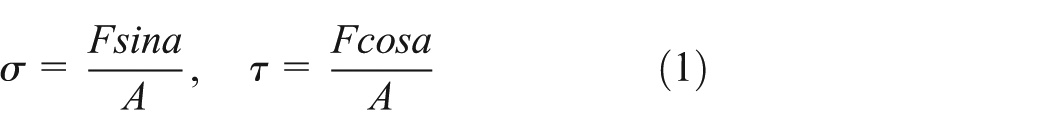
where F is the maximum load, A is the area of adhesive surface, and
Experimental data of the seven groups of scarf specimens.

RMS: ratio of normal and shear stresses.
Adhesive failure stress envelope
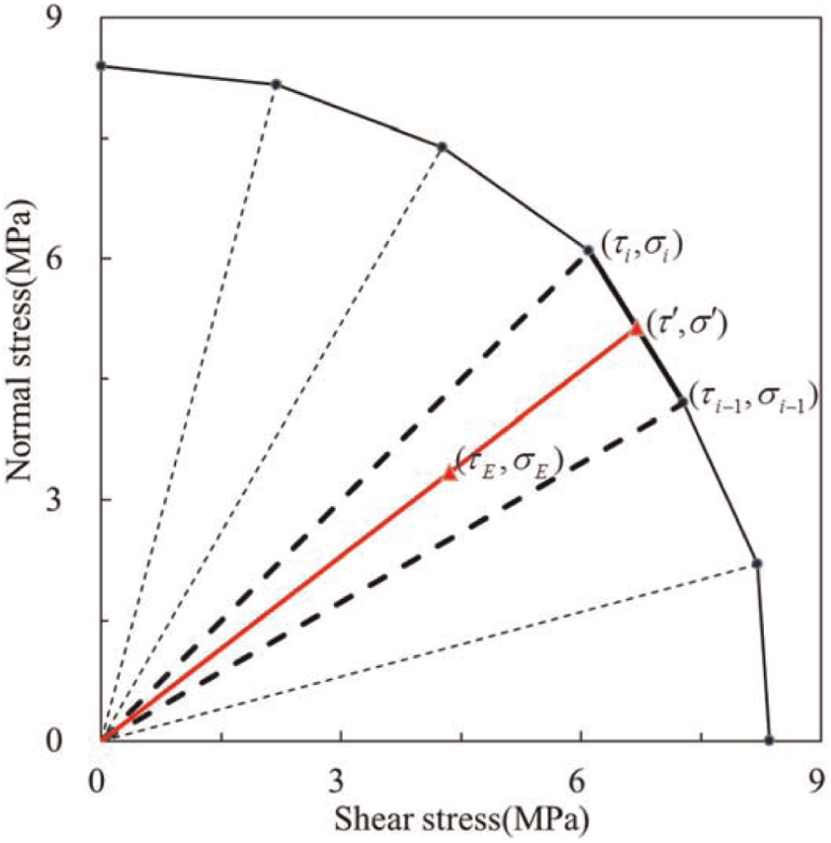
A coordinate system was created; seven stress points were plotted with the shear stress as abscissa and the normal stress as the ordinate from the data in Table 2. An adhesive failure stress envelope was created by connecting the seven stress points, as shown in Figure 4. The envelope represents a collection of the failure stresses under all RNS stress states. The seven stress points were connected with their coordinate origins. The coordinate system was then divided into six triangular areas, with the slope equal to the RNS. The corresponding adhesive failure stresses of the remaining RNS stress states can be obtained by interpolation between two adjacent stress points shown in Figure 4.

The adhesive failure stress envelope.
Adhesive strength evaluation process
The adhesive failure stress envelope has been obtained through experimental tests previously. Next, the stress state of the bonding structure needs to be analyzed and calculated to complete the evaluation of the adhesive joint strength. The specific procedures are as follows:
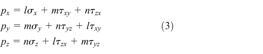
Finite element analysis of the bonding structure. The finite element model of the bonding structure was created. Loads and constraints were applied to the model according to the actual conditions and subjected to simulations. The stress values of the adhesive elements can be obtained in the simulation results and represented as six basic stress components (
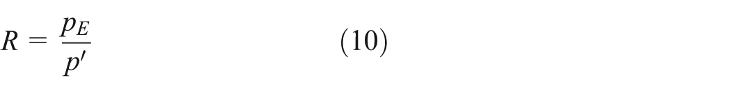
Stress coordinate transformation. In order to facilitate the comparison between the actual stress and the failure stress of the adhesive element, the obtained adhesive element stress (

The resultant stress of the adhesive element E was assumed to be
The normal and shear stresses of the adhesive element E were assumed to be

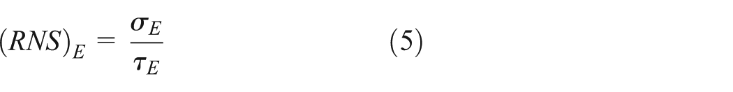
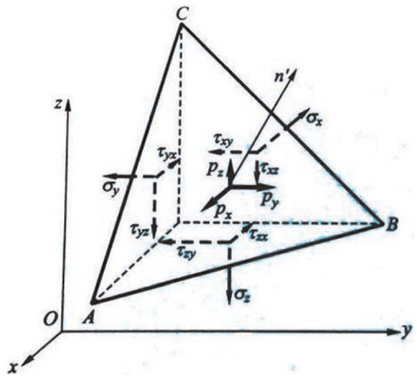
Failure stress of the adhesive element E. The RNS of the adhesive element E is given by equation (5)
The (RNS) E was compared with the RNS of seven stress points in the adhesive failure stress envelope, if

the adhesive element E was located in the (i − 1)th triangular area described in section “Adhesive failure stress envelope.” The envelope corresponding to the (i − 1)th triangular area can be expressed by stress points

The line between the point

The intersection
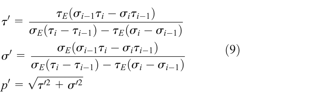
Strength evaluation of the adhesive element E.
R determines the strength evaluation result of the adhesive element E. R > 1 implies that the stress of the adhesive element E exceeds the failure stress; hence, the strength evaluation result is unqualified. For R ≤ 1, the stress of the adhesive element E does not exceed the failure stress, and the strength evaluation result is qualified.
Schematic diagram of the stress coordinate transformation.
Schematic diagram of the strength evaluation.
Advantages of the evaluation method
The contents described above are those of the proposed adhesive strength evaluation method which is very simple and efficient in engineering application. The advantages of this evaluation method are that it not only enables designers to decide whether the adhesive strength of each adhesive element in the bonding structure is qualified but also gives the ratio of the actual stress of the adhesive element to its failure stress. For some adhesive elements with a very small ratio, it can be considered that their adhesive capacity was not fully realized. According to these strength evaluation results, the engineering designers can improve the utilization of the adhesive by modifying the size or shape parameters of the bonding structure reasonably to further achieve the purpose of the bonding structure optimization design.
FORTRAN program
The number of the adhesive elements in the model is very large. Furthermore, the verification procedure was tedious because each adhesive element should be evaluated. To improve the efficiency and accuracy of strength evaluation, the evaluation process was written into a FORTRAN program. An executable file was generated for a rapid strength evaluation of the finite element model.
Verification test
Verification model
A verification program was designed to test the effectiveness and reliability of the evaluation method. The selected verification model shown in the Figure 7 was an intercept section taken from the side window bonding structures on the CRH3 high-speed train (Tangshan, China). 6005A aluminum and Sikaflex-265 were used as materials. Considering that the side window bonding structures are mainly subjected to tensile and shear forces during operation and that the verification model should be general, a loading device was designed which can apply both tensile and shear forces on the verification model, and its force centerline does not pass through the center of the adhesive layer, which makes the verification model more general, as shown in Figure 8.

Shapes and dimensions of the verification model (dimensions in mm).
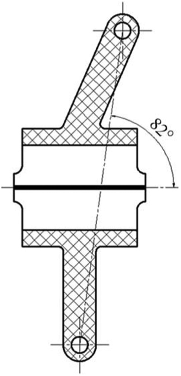
Schematic diagram of the loading device.
Experimental tests
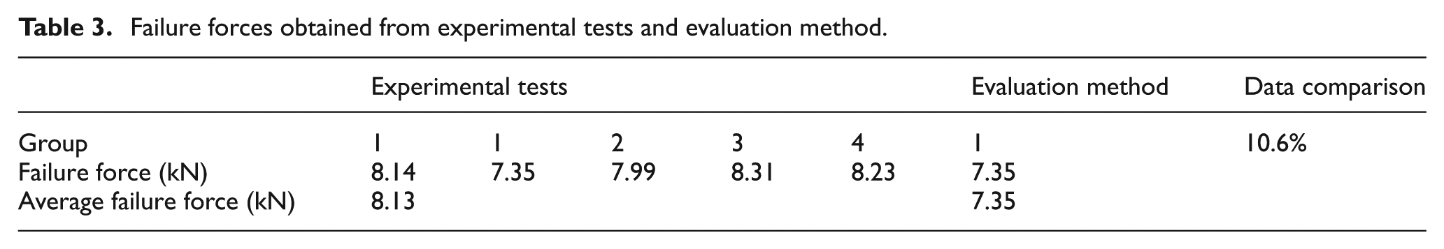
The same bonding structures were prepared as shown in the model in Figure 8. Both ends of the bonding structures were connected to the testing machine, one end of which was fixed and the other moved with the testing machine at a speed of 1 mm/min, as shown in Figure 9. The sample amount is 5. The failure forces were recorded in Table 3.
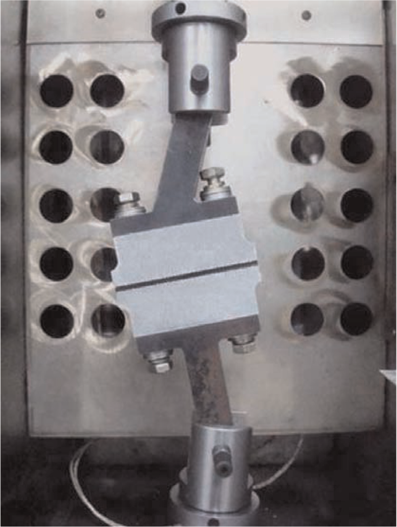
Experimental test of the verification model.
Failure forces obtained from experimental tests and evaluation method.
Simulation analysis and strength evaluation
The finite element analysis model of verification model was created using the pre-processor PATRAN. Eight-node isoparametric elements were used. The mesh size of the aluminum and loading device is 2.5 mm, while the mesh size of adhesive is 0.5 mm. The number of elements and nodes were 13,280 and 16,056 in the model, respectively. The material properties are shown in Table 1. In this process, the pin hole was fixed at one end of the model and an estimated force was applied to the hole at the other end of the model along the center of the holes, as shown in Figure 10.

Finite element model of the verification model.
Subject the finite element model to simulation analysis using Nastran processor; the basic material properties have been shown in Table 1. After the stress value of each adhesive element was obtained, the adhesive element was evaluated one by one using the method described in section “Adhesive strength evaluation process.” Then, the R-value of each adhesive element was obtained in the strength evaluation. The force in the verification model was resized according to the maximum R-value; if the maximum R-value is less than 1, then increase the force in the model; on the contrary, decrease the force. Re-simulation analysis and re-evaluation is needed for each adjustment of the force, until the maximum R-value is equal to 1. At this point, the force magnitude in the verification model is the maximum based on the strength evaluation method. The evaluation result is also presented in Table 3.
Comparison of evaluation result with experimental tests
The maximum forces in Table 3 were compared. The results revealed that the maximum forces obtained from experimental tests were high and increased by an average of 10.6%. Therefore, the results from the adhesive strength evaluation method were safe and exhibited specific amounts of conservatism. Furthermore, the evaluation method of adhesive joint strength was verified to be effective and reliable in engineering application.
Conclusion
A fast and simple strength evaluation method which can easily be used for the adhesive joint under complex working conditions was proposed in this article. The method has some advantages compared with other methods such as cohesive zone model method, continuum damage mechanics, and mixed-mode fracture method, which are fast, simple, and easy to use. The method is suitable for the adhesive joints under complex working conditions and can easily be understood and applied by the engineers.
BJ, SLJ, and several groups of SJ specimens with different adhesive angles were fabricated and tested to obtain the adhesive failure forces. According to the experimental data, an adhesive failure stress envelope was fitted. Furthermore, the evaluation method of adhesive joint strength and its detailed process were proposed on the basis of the adhesive failure stress envelope. Finally, a verification program which contains experimental tests and finite element analysis was designed for the adhesive strength evaluation method. The results of the verification program have demonstrated the effectiveness, easiness, and conveniences of the evaluation method of adhesive joint strength.
Footnotes
Academic Editor: Guoqiang Li
Declaration of conflicting interests
The authors declare that there is no conflict of interests regarding the publication of the article.
Funding
This work was supported by the National Natural Science Foundation of China under Grant 51075187.