
Abstract
Savonius wind turbine is a common vertical axis wind turbine which simply comprises two or three arc-type blades and can generate power under poor wind conditions. With the aim of increasing the turbine’s power efficiency, the effect of the blade arc angle on the performance of a typical two-bladed Savonius wind turbine is investigated with a transient computational fluid dynamics method. Simulations were based on the Reynolds Averaged Navier–Stokes equations, and the renormalization group
Introduction
Wind turbines are generally divided into two categories, horizontal axis wind turbines (HAWTs) and vertical axis wind turbines (VAWTs), based on the relative position between their rotation axis and the wind direction. VAWTs are more favored in small-scale power generations because they respond to flow from any direction and allow generating equipment to be located on the ground shaft, and the maintenance costs can be reduced.
Savonius wind turbine is a common VAWT which generates torque through the combined effects of drag and inside forces and typically comprises two or three arc-type blades. 1 Savonius turbine has the following advantages over other types of wind turbines: (1) ability to operate under complex turbulent flows; 2 (2) low rotation speed and noise emission; 3 (3) simple structure, low cost.
However, the Savonius turbine has a relatively lower power efficiency, with a maximum efficiency of 0.25, 4 compared with the lift-type wind turbines, such as HAWTs and Darrieus wind turbines. In order to increase the efficiency, comprehensive studies have been done to examine the effects of various design parameters, such as the rotor aspect ratio, the overlap, the number of blades and the endplates, on the performance of Savonius turbines with experimental and numerical methods.1,4–7
In addition, some researchers worked to enhance the Savonius turbine performance by changing the structure of the turbine. Gupta et al. 8 studied the aerodynamic characteristics of a modified Savonius turbine with helical blades. Golecha et al. 9 and Altan and Atilgan 10 placed a guide vane in front of the turbine to deflect flow for the returning blade. As for the novel blade shape design, McTavish et al. 11 proposed a modified blade shape and carried out both steady and transient computational fluid dynamics (CFD) simulations. Kamoji et al. 12 and Kacprzak et al. 13 studied the performance of modified turbines with spline-type and Bach-type blades, and an incensement of 16% in the efficiency was found in the case of using spline-type blades.
This article aims to increase the efficiency of Savonius wind turbines by analyzing the effect of the blade arc angle on the turbine performance and to find the optimal arc angle corresponding to the maximum efficiency. The analysis has been performed by solving numerically the incompressible Navier–Stokes equations with the aid of the CFD code Fluent 13.0. 14
Parameters definition
The two-dimensional schematic view and geometrical parameters of a two-bladed Savonius wind turbine are presented in Figure 1, where U is the wind velocity, θ is the azimuth angle of the blade, ϕ is the blade arc angle, ω is the rotation velocity of the turbine, r is the blade radius, and D is the turbine diameter.

Two-dimensional schematic of the Savonius turbine.
In order to investigate the effect of the blade arc angle, ϕ, on the performance of the turbine, we performed simulations on turbines with ϕ varying from
Main structural parameters of the tested models.

Numerical method
Because the straight blades have the same cross section in the span direction, the blade span effect can be ignored and two-dimensional transient simulations are carried out with the aid of the commercial CFD code Fluent 13.0. A sliding mesh model was applied to realize the rotation motion of the rotor.
Computation domains and boundary settings
In order to allow a full development of the flow as well as decrease the blockage effect, the computational domain was a rectangle of
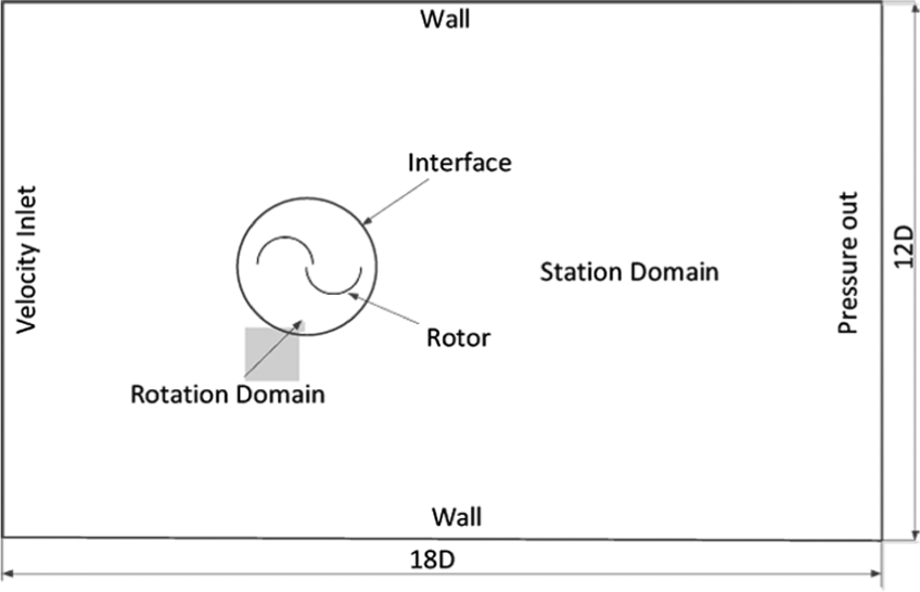
Computing domains and boundary conditions.
The boundary conditions employed consist of a constant velocity inlet (7 m/s) on the left side, a pressure outlet on right, and two symmetry boundary conditions on top and bottom. No-slip boundary conditions were imposed at the surface of the blades. Siding interfaces exist between the external stationary domain and the internal rotational domain, allowing the transport of the flow properties.
Grids generation
The computation grids were generated using the MESH tool in ANSYS 13.0. Quadrilateral elements are less memory-occupying than triangular elements (the number of quadrilateral elements is only a half of the triangular elements considering the same grid nodes number) in two-dimensional simulations and more suitable for simulation of the boundary layers flow. Therefore, the two subdomains were discretized with quadrilateral elements (see Figure 3(a)). As can be seen in Figure 3(b), grids closest to the profiles of the blades were refined with boundary layer elements to describe with sufficient precision the boundary layer flow. The Reynolds number was computed based on the wind speed and the blade chord length, resulting in a value of about

Grids generation for (a) the station domain and (b) the boundary layers.
Turbulence model and solution sets
The renormalization group (RNG)
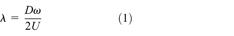
For each case listed in Table 1, several simulations were carried out with the tip speed ratio varying from 0.6 to 1.4. Tip speed ratio represents the ratio of the blade tip speed to the wind speed and has the following expression
Each simulation lasted for three revolutions. The time step used was set as 1°/step, that is, the rotor turned 1° in each time step, and each time step takes 100 iterations. Convergence was determined by the order of magnitude of the residuals. The drop of all scaled residuals below
Numerical method verification and validation
Verification
A grid convergence study was performed to evaluate the influence of grid density on the torque of the rotor. The simulations were conducted on a conventional Savonius turbine with

Results for grid convergence.
Torque coefficient is defined as follows

where M is the generated torque, and S is the cross section area, given by the relationship S = DH with H being the height of the blade. Since only two-dimensional simulations were performed, the unit height
Validation
Validation studies were conducted using a conventional two-bladed Savonius turbine, that is, the case 4 turbine. The simulation results are then compared with the experimental data from the SANDIA lab. 4 Figure 5 shows the comparison between the coefficients of averaged torque on the rotor at a range of different tip speed ratios.
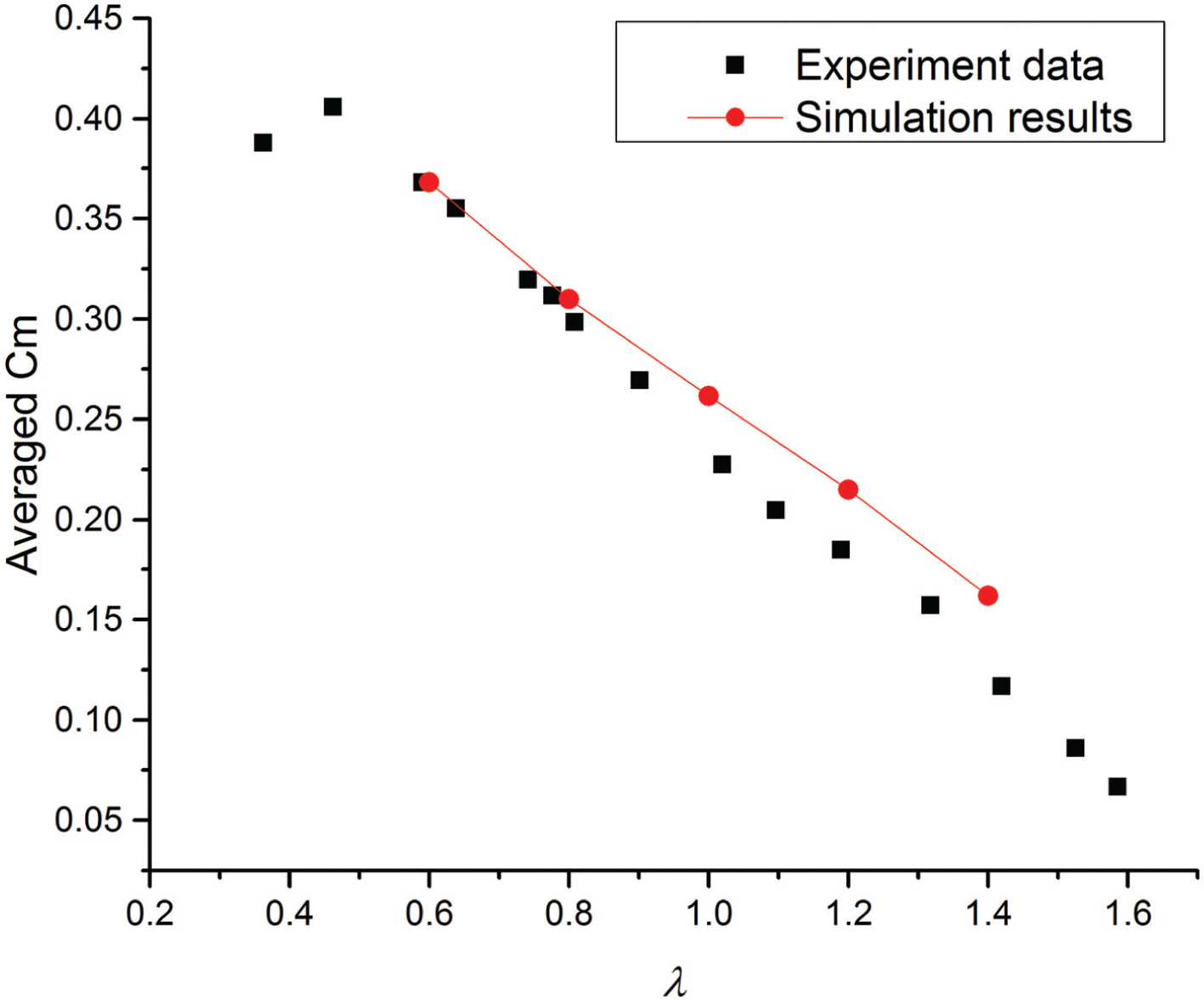
Results for numerical method validation.
It can be seen that the simulation results coincided well with the experiment data, especially at lower tip speed ratios. Therefore, it is acceptable to use the RNG
Results and discussion
Torque characteristics
Keeping the wind speed constant, simulations were carried out for cases 1–6 at different tip speed ratios. Figure 6 shows the coefficients of the averaged torque on the turbines with respect to

Coefficient of torque with respect to
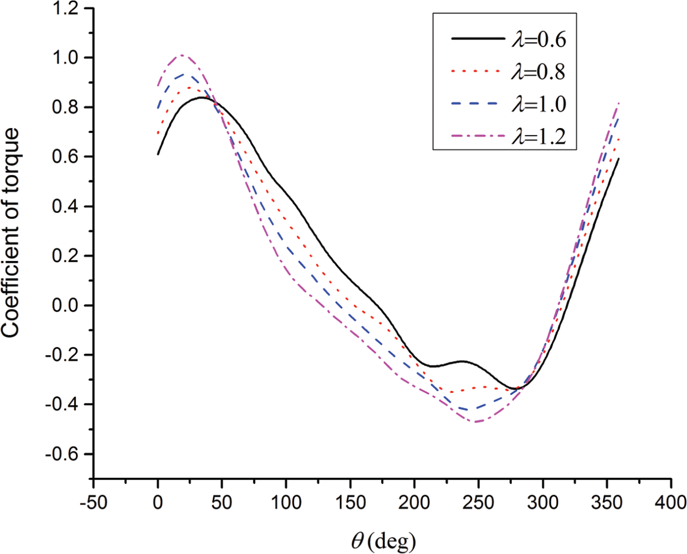
Blade dynamic torque coefficient for the case 4 turbine at different tip speed ratios.
Figure 7 shows the dynamic torque on a single blade of the case 4 turbine for a whole rotation cycle. The torque curves are plotted with respect to the azimuth angle θ. As
Power characteristics
The coefficient of power is defined as

where P is the generated power. Figure 8 shows the coefficients of power generated by the turbines with respect to

Coefficient of power with respect to
Table 2 lists the maximum coefficient of power for cases 1–6. It can be seen that the turbine efficiency can be obviously enhanced by choosing a proper blade arc angle. The turbine with a blade arc angle of
Maximum coefficient of power for each case.

Mechanism of the effect of blade arc angle on the turbine performance
Figure 9 shows the dynamic torque on a single blade with different arc angles for a rotation cycle at

Blade dynamic torque coefficient for different blade arc angles at
Figure 10 shows the pressure distribution on the blade of cases 2, 4, and 6 turbines at

Pressure distribution on the blade of cases 2, 4, and 6 turbines at
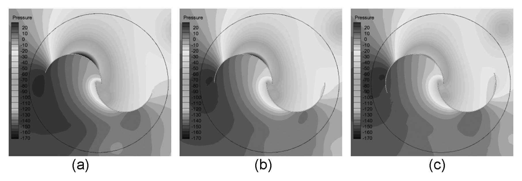
Pressure contours of cases 2, 4, and 6 turbines at
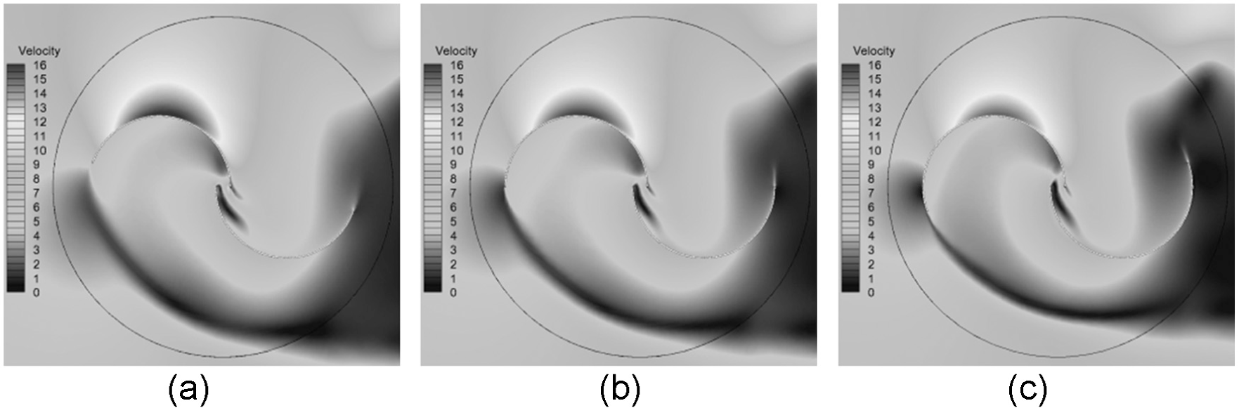
Velocity contours of case 2, 4, and 6 turbines at
It can be seen in Figure 11 that a negative pressure area exists on the convex side of the blade, and as blade arc angle increases, this area gets smaller and weaker. This is because that there is a stream with high velocity near the concave side of the blade (see Figure 12), and as the blade arc angle increases, the blade becomes thicker and longer and has a higher aerodynamic drag on the flow and thus reduces the flow velocity (also see Figure 12). It is the drop of flow velocity that decreases the negative pressure. Besides, a slight drop in the pressure on the concave side of the blade is also observed (see Figure 11). This is possibly caused by the shelter-effect of the blade. Blade with a larger arc angle has a longer tip, which impedes the wind to flow from the upstream to the concave surface of the blade and reduces the torque on the blade.
Figure 13 shows the pressure distribution on the blade of cases 2, 4, and 6 turbines at

Pressure distribution on the blade of cases 2, 4, and 6 turbines at
Figure 14 shows the pressure contours of three turbines at
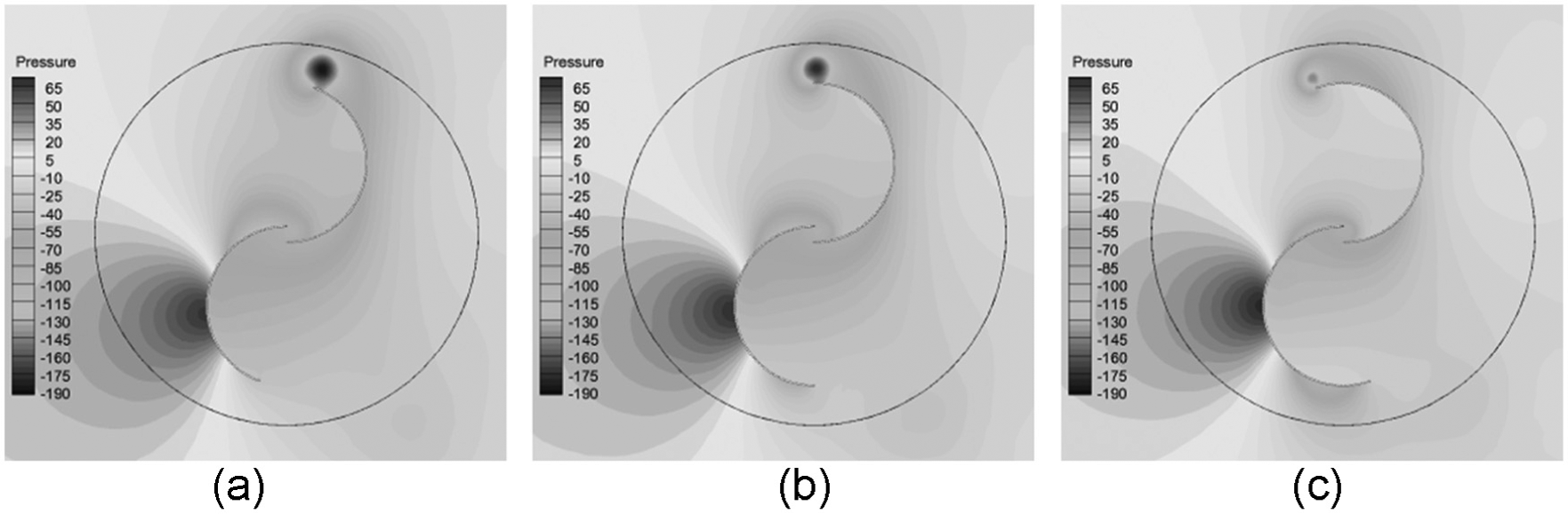
Pressure contours of cases 2, 4, and 6 turbines at
Centers of pressure of the blades at

Conclusion
Two-dimensional CFD simulations were performed on Savonius wind turbines. The effect of the blade arc angle on the turbine’s torque and power performance was studied. The mechanism of how the blade arc angle affects the turbine performance was explained with field contours. We find that the positive peak torque on the blade can be increased by reducing the blade ellipticity, while the negative peak torque is on the contrary. Turbine with a blade arc angle of
Footnotes
Academic Editor: Ramiro Martins
Declaration of conflicting interests
The authors declare that there is no conflict of interest.
Funding
This research was supported by the National Science Foundation of China (Grant No. 51179159).