
Abstract
Hydraulic generator design companies are always being exhorted to become more competitive by reducing the lead time and costs for their products for survival. Knowledge-based engineering technology is a rapidly developing technology with competitive advantage for design application to reduce time and cost in product development. This article addresses the structure of the hydraulic generator design system based on the knowledge-based engineering technology in detail. The system operates by creating a unified knowledge base to store the scattered knowledge among the whole life of the design process, which was contained in the expert’s brain and technical literature. It helps designers to make appropriate decisions by supplying necessary information at the right time through query and inference engine to represent the knowledge within the knowledge-based engineering application framework. It also integrates the analysis tools into one platform to help achieve global optimum solutions. Finally, an example of turbine-type selection was given to illustrate the operation process and prove its validity.
Keywords
Introduction
Hydraulic generator is an efficient and flexible device which can transfer the energy of water to electricity. It can be an excellent method to get renewable energy from rivers and streams. 1 It is a typically customizing and complicated machine with a complex structure, great amounts of outfit items and size information, whose design process includes scheme design, complex components design, electromagnetism calculation, Ventilation and Cooling design, force analysis, and global optimization. The whole design process starts with customer’s requirements and needs lots of distributed knowledge to fulfill the satisfactory products including many labor-intensive activities. The main structure of the hydraulic generator is shown in Figure 1.

The main structure of the hydraulic generator.
In the traditional design environment, the design knowledge and process are de-coupled as they are undertaken by different experts applying different software tools and using separate analysis methodology to predict the resultant effect. This situation is shown in Figure 2. The parts of machine were designed separately among different departments according to the customer’s requirement and other influence factors. In many cases, the geometry model, finite element (FE) analysis, and parameter calculation for the product are generically essentially the same for many generations of structure members; sometimes even details have to be changed a little. Once customer’s requirement changes, the engineers should modify their individual design results; they even need to change the original models until a satisfactory result can be obtained. Obviously, the repeated modification and analysis process takes majority of the time and energy of the designers; just little time is left for them to do creative or fire-new designs. That shows the imbalance between the time required for noncreative activities and the time available for the exploration of innovative design spaces. 2 And at the same time, lots of design parameters information and expertise get accumulated, then are assimilated and understood by the designers during the design process. If the discipline expert resigns or is absent from the position, the valuable and abundant knowledge sticking to him would vanish from the company. And the new employee has to relearn the knowledge and get experience all over again from the daily work which is a time-consuming process. So, the designers heavily depend on their experience and the existing knowledge resource accumulated. Consequently, we urgently need a methodology to acquire, store, reuse, and manage the knowledge accumulated. 3
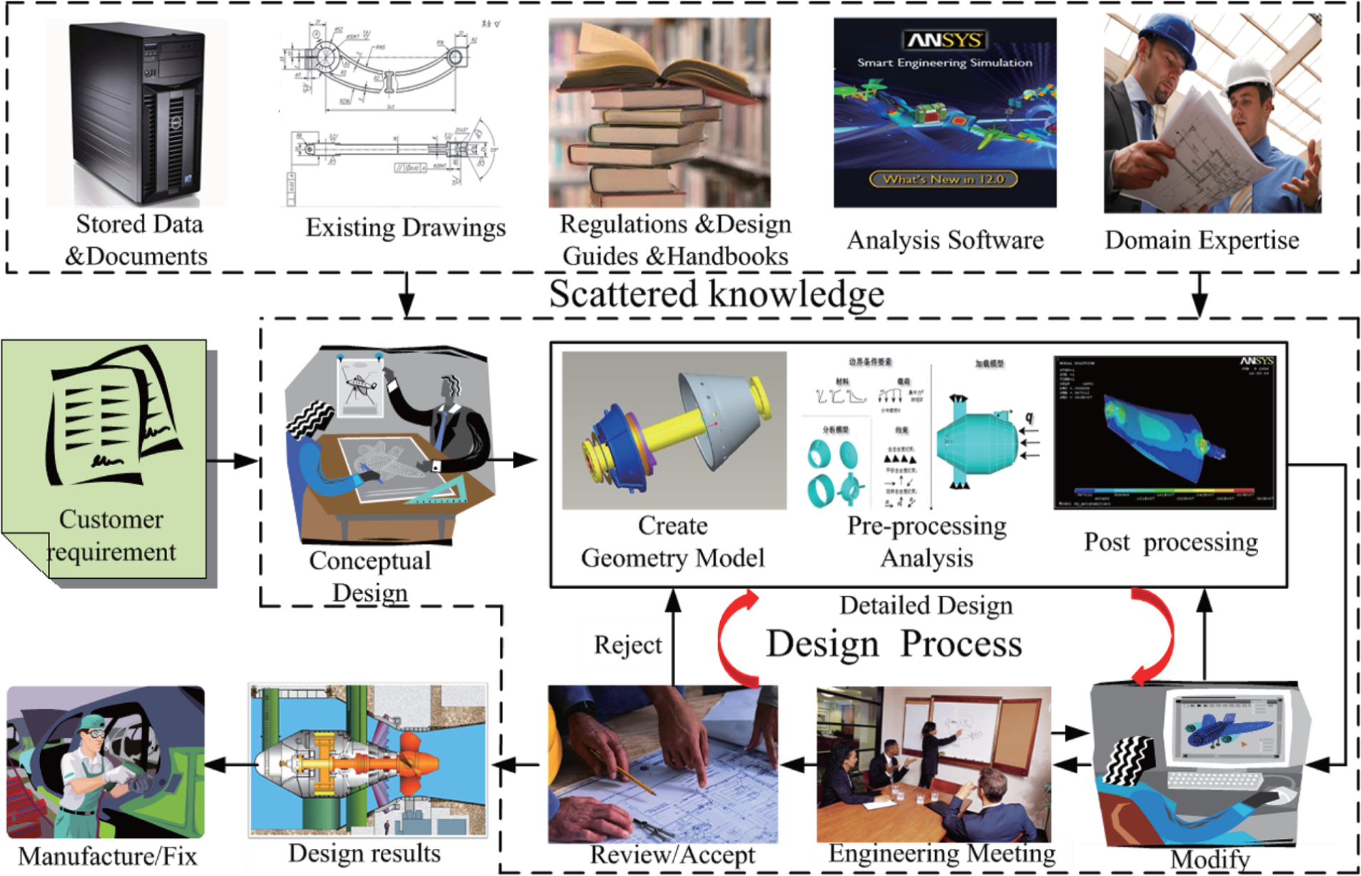
The traditional design process and life cycle of the hydraulic generator.
In order to face the competition of the hydraulic generator design (HGD) market, people have to reduce the development cost and shorten the lead time. The design process is one of the critical factors that determine the cost, quality, and cycle of the product. 4 In the HGD process, there exists a large amount of knowledge stored in different formats. In the design domain, knowledge-based engineering (KBE) is the most common way to support customization and automotive design that could shorten the lead time, and also improve quality and profit. Therefore, it is urgent to apply the KBE technology to support the HGD in order to change the current status described above.
According to the HGD features, Harbin Institute of Technology 3 has developed a bidding scheme system of large-scale hydraulic generator by analyzing the comparability between the historical cases in database and the current scheme design to find out the best analogical case, which could also realize the optimization of the scheme and make it fit for the current design requirement. Gui Lin 5 proposed a system to select the proper type of stator winding to meet the requirement of electric machine design and relaying protection. Li Donghai 6 built a knowledge base which presented a set of principles applied to the design of the governor of a hydraulic generator, achieving a highly efficient and flexible design environment. Zhu Dianhua et al. 7 have proposed a platform to seek for optimized solution for the conceptual design. These methodologies focused on the single design stage of the process, so cannot supply a unified framework to manage all the design stages and manage the knowledge accumulated properly.
In this article, we proposed an integrated framework named HGD system to manage the design process and apply it to acquire, store, and reuse the scattered knowledge. Within the framework, we apply the methodology of KBE to parametric models of structure members. The calculation modules can be developed and used separately which can be easily modified. In addition, several types of knowledge bases can also be established to store different types of knowledge. Furthermore, the auxiliary tools are applied to create the link between the knowledge nodes. Thus, it helps designers to make appropriate decisions by supplying necessary information at the right time through query and inference engine to represent the knowledge within the framework. It also integrates the analysis tools into one platform to help achieve global optimum solutions.
This article is organized as follows. In the next section, we explain the basic principles of KBE technology and summarize the steps to execute the methodology. Section “The framework of the HGD system” introduces the HGD system in detail; section “Design example” gives a design example to accomplish the turbine-type selection design task based on the HGD system. Finally, section “Conclusion and future studies” of this article present our conclusion.
Basic principles of KBE
Knowledge and KBE
Knowledge is a highly structured form of information or what is required to perform complex tasks.8,9 It is the vital component of engineering design including design standards, product specification, expert knowledge, experience, and successful precedents. These different formats of knowledge can be used as follows: (a) to disseminate knowledge to other people in the hydraulic design company; (b) to reuse knowledge in different ways for different analysis or calculation; and (c) to use knowledge to develop the intelligent system which can perform complex design tasks. 10
KBE is a rapidly developing technology with an enormous potential for engineering design applications. It stands at the point of diverse fundamental disciplines, such as artificial intelligence (AI), computer-aided design (CAD), and computer programming.11,12 There have been many examples of KBE being successfully used to help design products that require knowledge from various activities during the whole design process. For example, Chapman and Pinfold 4 described a KBE system to extend the capabilities of body-in-white (BIW) engineers. The system allows output to respond dynamically to changes within a rapid timeframe and to assess the effects of change with respect to the constraints imposed upon by creating a unified model description that queries rules. 13 HZ Yang 10 has presented a KBE methodology for ship structural member design. It achieves knowledge reuse and accumulation and provides reliable technical support for ship design quality. 10 Textron Aerostructures announced the deployment of a tooling design application that delivered a 73% reduction in design time. Jaguar have reduced the time to design an inner bonnet from 8 weeks to 20 min by developing a KBE system, while Boeing have published that approximately 20,000 parts for the 777 aircraft have been designed using this technology. 14 The KBE methodology is not only widely applied in mechanical engineering field, but also used in supply chain management. Dongming Xu et al. 15 have presented a novel outbound exception monitoring system by introducing multi-intelligent agents, which can ensure autonomous, flexible, and collaborative exception monitor in logistics. Besides the research on whole system creation, some novel methodology used in the steps of accomplishing the system also appeared. RF Hamade et al. 16 proposed a knowledge acquisition approach based on Nested Ripple Down Rules (NRDR) to build a dimensional tolerancing knowledge management system which could help mechanical designers become more effective.
The core of KBE is to integrate professional knowledge, domain knowledge, user’s maturity design experience, the choice of design parameters based on experimental data, material data, user’s feedback, and relevant design standards and norms into the design of software through the logical judgments and deduction, achieving product intelligent design.10,17 Adopting KBE can be very beneficial to increase the ability to innovate, get products to market faster with reducing errors and the final cost.
The steps of KBE application
The application of KBE to the design process of hydraulic generator can be divided into several steps: knowledge acquisition, knowledge representation, reasoning mechanism, and establishment of knowledge base. It emphasizes on reusing product design knowledge, experience, and other formats of knowledge in the HGD process and developing creative products at top speed. 18
Step 1: knowledge acquisition
Knowledge acquisition is the activity of capturing expertise from people (and other sources of knowledge) and creating a computerized store of this knowledge to be used to help an organization in some specified ways. 19 The resources of design knowledge always include documents, books, websites, experienced designers, experts, databases, experiments, successful precedents, design drawings, and even the feedback information from the manufacturers and sellers. For the most valuable knowledge stored in the experts’ brain, we collect it by interviewing the experienced designers per fixed period; for the knowledge recorded in the web pages or in the files, we get it by using the aided tool to grab the data we need and transfer that to standard formats. Then, the knowledge can be represented as if–then rules or structured cases embedded in the proposed system to facilitate the design process.
Step 2: knowledge representation
Knowledge representation focuses on how to state problems and how to store knowledge in a machine-interpretable representation to facilitate computers to take advantage of knowledge in the knowledge base to address complicated and difficult problems. Generally, which method should be chosen for knowledge representation depends on the type of knowledge and its operation mechanism.
Step 3: knowledge reasoning
Knowledge reasoning is the thinking process which is deducing another judgment known according to a strategy. The reasoning methods mainly include rule-based reasoning (RBR) and case-based reasoning (CBR).20,21 The method of RBR is used for specific parameters and rules based on maturity theory and experienced designer. The CBR method is used for parts and components design similar to precedent-based product knowledge templates and successful practice cases. In this article, we use both the RBR and CBR embedded in the system to retrieve the needed knowledge and then apply the results to the designers. In the example of turbine-type selection module given in section “Design example,” the if–then rules are embedded in the system by Java scripts.
Step 4: Establishment of knowledge base
The knowledge base is defined as a collection of experience, rules, cases, and other knowledge. 18 In KBE design methods, knowledge including expert knowledge, experience and product design standards, product specifications and successful precedent is collected, sorted, and summarized into a number of rules, analysis, and problem-solving strategies and is placed in a particular form of the document or database to constitute a knowledge base, which can achieve storage and classification management of product design knowledge and provide best guidance and recommendations for the designer during the design process.
Take the calculation module as an example to present the creation process of knowledge base. In this article, we supply the friendly user interface for the designers to create the knowledge hierarchy tree as shown in Figure 3. Applying the auxiliary tool, customized knowledge nodes can be defined and added to the knowledge tree and can also be modified conveniently.

Rule and formula editor tool interface.
For the calculation module, the complicated relationships between parameters can be created by the editor tool as shown in Figure 4. Each parameter’s specification and unit can also be modified in advance.
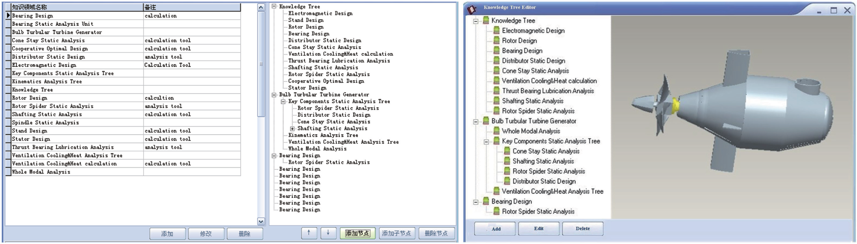
The knowledge tree of the hydraulic generator.
Also, other kinds of subsets of the knowledge base, such as standard component library, Calculation cases, material library, and the finished drawing documents, can be collected and embedded in the unified knowledge base, as shown in Figure 5 as an important layer of the framework of the HGD system.

The architecture of the hydraulic generator design (HGD) system.
The framework of the HGD system
The system architecture is a network infrastructure, which uses a distributed system design to connect the different platform systems in a sophisticated network infrastructure. We collect HGD knowledge that is distributed in diverse stages and different computer-aided tools and use the KBE methodology to create design rules and workflow criteria. Then, we integrate the design information with a document-based system and use an inference engine to provide an integrated framework for generator design. The architecture of the hydraulic generator is shown in Figure 5; it includes four layers: the knowledge resource bases layer which is the infrastructure, above it is the computer-aided tools layer, then the resource integrated and management layer, and the user interface is at the top of the architecture. In this article, we just addressed the intelligent design of the turbine runner by the computation capability of the HGD; other functions of the HGD system will be discussed in other articles.
The knowledge integration management
Knowledge about engineering design processes constitutes one of the most valuable assets of a modern enterprise. Normally, this knowledge is only known implicitly to the participating designers, relying on the personal experience background of each designer. To fully exploit this intellectual capital, it must be made explicit and shared among designers and across the enterprise. 22
The integration management layer is the core component of the system used to control the whole workflow which disassembles the design task into several stages and applies tools interface to reach the needed knowledge. The design process involves extensive information exchange and communication among distributed teams, so it is necessary to set the unified work environment including unified international units, unified component names and accepted document formats. Another function this layer applies is the operation rights management which limits the person who can modify and update the information in the knowledge bases.
Calculation and optimization module
The computer-aided tools layer applies the needed modules to support the model creation, force analysis, and numerical calculation processes. Several design modules were developed to support the calculation and optimization task. In this article, we focus on the parameter calculation by applying the KBE technology and validate its efficiency by an example of turbine-type selection in the next section.
In order to make perfect decisions, the designers have to do lots of numerical calculation by changing some parameters to assess the influence brought in until a satisfactory goal is achieved. These processes may be repeated many times just for one part design which is mundane and time-consuming. The calculation modules are developed and used to automate all or part of the process, which can significantly shorten the design period and free the designers from the lengthy and boring work.
Generally, the calculation process of products and components design is finished separately, so the results and parameters selected are just the best practice of local optimum. Then, more parameters have to be taken into account and require a loop of design–evaluate–redesign to get the best solution. In the traditional design process, designers adjust the parameter manually to gain the best solutions. 23 However, this method is extremely time demanding and it is prone to errors as the number of variables increases. 24
The optimization module (shown in Figure 10) provided by the HGD system supports the process taking the constraints from different sources into account and achieving the global optimal, which could aid the designer in determining the feasibility of the original design or in further optimization and redesign strategies.
Software interface and user interface
The hydraulic generator is a typically complex machine, whose design process is accomplished by going through several different CAD platforms scattered such as Pro/E, ANSYS, ADAMS, and FLUENT to optimize the design. In most of the time, a design engineer has to work with two or more independent software packages for modeling and analysis and yet has to maintain the associativity by checking the constraints applied throughout the engineering processes. However, due to the tedious dependency relations and the lack of management tools, it is difficult to avoid losing model integrity. 25
The HGD system applies the software interface to merge the tools used in the process into a single one that allows the designers to create the 3D models, finish the analysis work, and view and modify the documents of all accepted formats much more conveniently within one platform. The software mentioned above can be triggered directly when the designers require the tools to do the analysis task or operate the document stored.
The 3D geometry models and drawings are stored in the bases with different version ID that make it easier to reuse them. The user interface is used as design process navigation tool and information input bridge between the designers and the system. The key point is setting a unique format for all the same kinds of documents which enable it to communicate easily among the designers.
Design example
The turbo runner design process
Take the selection as an example in accordance with the HGD. The first step to implement the design task is to decide the main blueprint including the type selection of the hydraulic generator, the core component’s structure, and key parameters. It would take much time to use the trial-and-error method to decide the parameters because each design step contains much knowledge and rich experience. Above all, the type selection is the first and most important step of the HGD, which relates closely with the further design and calculation analysis and optimization process. The HGD system provides the designers with knowledge management and calculation tools to analyze and model products, control the design process, and capture and reuse the associated knowledge.
Designing the satisfactory model runner according to the parameters of the power station is the key step in the HGD process. Depending on the performance of the model runner, the first step for the designers is to choose the appropriate turbine type according to the information collected including flow rate, water head, hydrology data, and specific speed. Then, supply the synthetic characteristic curve for the further design such as deciding the main property parameter and structure control parameters and choosing the type of turbocharger housing, guide vane, and draft tube. Traditionally, designers finish these kinds of time-consuming work by tedious and repeated calculation manually. The design process can be sketched in Figure 6.

The synthetic characteristic curve of turbine runner.
At this design phase, a large number of existing design cases are needed for reference. Through the HGD system, relating cases can be retrieved accurately according to the customer’s requirement. Then, the designers can make necessary change within the system and the results can be stored simultaneously. We will take the process of choosing the type of bulb turbine generator in detail as an example to demonstrate the calculation function of the HGD system. The decision making and parameters selection process can be described in five steps.
Step 1
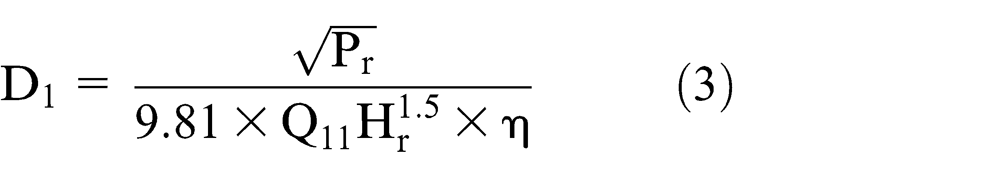
The unit power capability and the number of units should be decided. The selection of the output power (P) is based on the maximum water head (

where C is the budget of the generator and N is the number of the units. After making sure the output power of the hydraulic generator, we could make further decisions according to the result. Each generator has a unique operation environment, and in order to design the hydraulic runner with high efficiency, the common method is to do the model experiments according to the similarity theory which means that the runner has similar characteristics to the similar geometry size ones. The synthetic characteristic curve (shown in Figure 6) can be used to show the relationship between the parameters which cannot be easily described by formulas. The curve described the interactive relationship between several parameters including the unit flow (
Step 2
In the generator design process, it stipulates calculating the output power according to equation (2) 26

Here,
Step 3
In order to reduce errors, the value of

Step 4
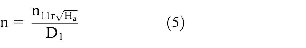
The rotational speed of the turbine runner can be calculated according to the following equation (5), where
Step 5
When the values of

where
Smart design of turbine runner
As described above, the iterative calculation process is time-consuming and may lead to the occurrence of errors. Within the HGD system, the turbine-type selection module is applied to automotives this task. The first step of the smart design is to establish a feature-based standard parametric modeling part library; designers can create the part by the software auxiliary function quickly. The second step is extracting and storing the characteristic parameters of standard parametric model parts and adjusting standard parts features and structure through changing these characteristic parameters. In addition, it consists in establishing a link among these feature parameters and summing up expert knowledge, design methods, and professional knowledge as knowledge rules, formulae, checks and rules, behavior, or other knowledge in a machine-interpretable representation, which can carry out the quantitative assessment of design in accordance with feature parameters. The process of turbine-type selection is shown in Figure 7.
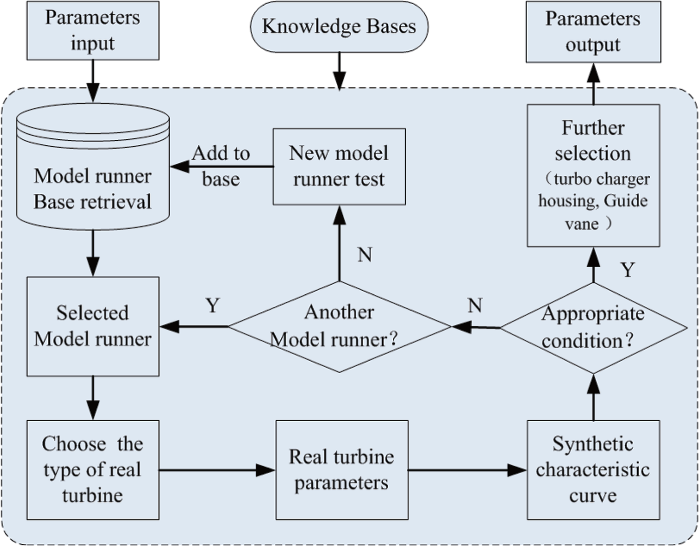
The process of turbine-type selection.
Through the above processes, we can check the key work conditions of the turbine and select an appropriate one. In order to save time, we turn to the HGD system applied the KBE methodology to accelerate this process by storing the synthetic characteristic curves, formulas, and parameters in the database and using related decision criteria to check the design results. The program and the related bases act as the knowledge carrier to automate this lengthy task. Through formula editor, the relationship between the parameters and judge criterion can be easily established and modified. The formula editor window is shown in Figure 3. Designers could easily define the parameters and establish the relationships between them.
The turbine-type selection module contains the synthetic characteristic curve, the calculation formulae and the turbine runner base to support the design process in the HGD system. The Java Script as the knowledge carrier was chosen to set the design calculation loop representing the knowledge needed. In the beginning of defining this module, the synthetic characteristic curve and the judge rules are embedded in the scripts. And the successful cases and history data are stored in the knowledge base. Thus, the designer just needs to input the value of the input parameters such as maximum water head (

Turbine-type selection module interface.
After confirming the main property parameters of the generator based on the type of turbine runner, then step into the stage of structure design of the generator by establishing the relationships between parameters through different formulae and parametric models.
In the latter design, through adding the general purpose CAD and analysis tools to the software base, we can easily change the product model by modifying the parameters according to the analysis results in the system. In order to achieve this function, used rules were converted to formulae and embedded in the program script. The global parameters are collected and stored in the knowledge base and the unified international units are used. In order to modify, change and add the calculation methods and check the criteria conveniently, several calculation modules are established separately, through each one can get access to the global parameters. These calculation modules include the ventilation cooling and heat module and electromagnetic vibration calculation module. The calculation interface windows are shown in Figures 9 and 10.
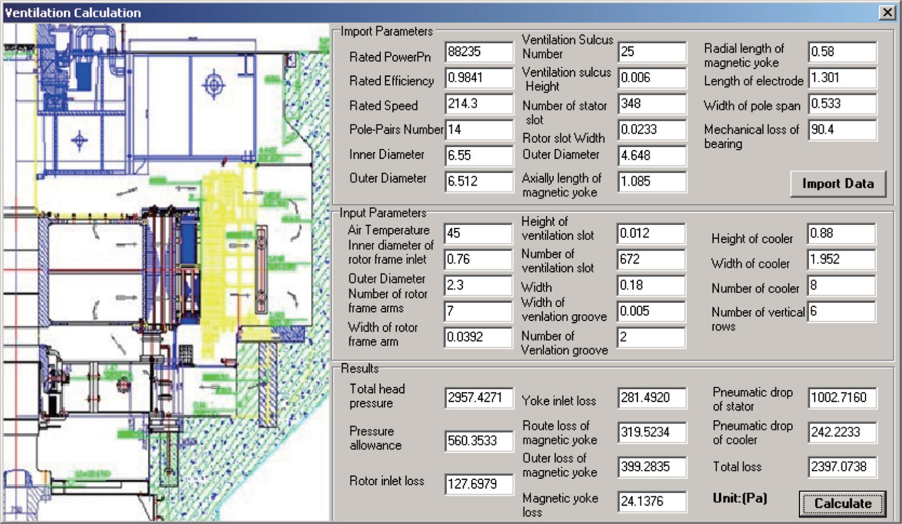
Ventilation cooling and heat calculation module.

Electromagnetic vibration calculation module.
Parameter calculation module is a tool to merge the repetitive parameters calculation tasks scattered in different stages into a single database. Thus, designers in different processes can edit and modify the relationship between these parameters, accomplishing the process of formulae input. This tool allows them to preview and assess the effects of change with respect to certain key parameters imposed upon them. Then it helps them to modify the design and make the design meet the scheduled design requirements in relatively short time. These parameter calculation modules can be developed separately and then embedded into the framework of the HGD system to realize the specialized function.
Through the calculation modules, the local optimal solution can be easily obtained, but it may not be the global optimal solution. The HGD system applies the optimization module to search for the global optimal solution. It starts the commercial tools such as MATLAB and ANSYS which are correctly installed in the operation environment through the interactive interface. So, the designers need not shift to other design platforms to modify the parameters, view the curves, and judge the impact imposed by the change in the value until the optimal tasks are fulfilled. In Figure 11, the optimization module triggers the analysis tool MATLAB to compare the difference between three design solutions to choose the best practice.

The global optimal Tool window.
Finally, we can smoothly get the customizing design report supported by these calculation and optimization modules; it contains all the results of required parameters. Thus, the rapid feedback information could be checked in the engineering meeting and used as the criteria for the manufacturing phase. If the end-user agrees with the design scheme, the output report could be filed into successful cases. The task emphasizing on the global optimization of the HGD is also a complicated task which will be discussed in another paper particularly.
The HGD system unified the scattered knowledge and design tools into a single one. It supplies a platform to capture, accumulate, store, and reuse the valuable experience and design rules. The reasoning mechanism is used to make decisions automatically according to the relationship between the parameters. Through the HGD system, designers just need to input the needed parameters and coefficient; then the system will check each parameter according to the rules established to make sure it is correct and output the results. This frees the designers from time-consuming and repetitive tasks to do more creative work.
Conclusion and future studies
Conclusion
The KBE is useful for the designers in the design process of hydraulic generator. It not only saves lots of time by exploring and storing all the knowledge needed of the whole life design through gradational structure, but also integrates several scattered software tools by interfaces to provide reliable technical support to obtain the best practice.
The whole process may take about 3–4 months to meet the requirements without using the HGD system. We successfully shortened the variant design period to about 1 month by applying the design system in a local generator design company which obtained better economic benefits through several times of system modification in order to satisfy their practical needs.
This system not only just saved design time drastically by means of controlling the workflow and the application of the KBE methodology, but could also provide help, analysis suggestion, and explanations to the engineer when required; thus, the designers no doubt can be well trained and can make proper decisions quickly. It supports the whole process from the type selection of turbine to the components calculation and simulation analysis of the generator. Thus, by using the HGD system, the calculation and analysis department can respond much more quickly to design scheme changes imposed by other departments. It also means that the investigation of choosing new parameters to optimize the design is much easier and quicker to judge the results. While the system is designed specific to the hydraulic generator, the methodology used is generic and can be applied to other product where scattered knowledge could be reused effectively.
To have an advantage and win contracts in the competitive hydraulic generator manufacturing market, we need to design products in a smart way. The presented work contributes to the methodology of how KBE can be used in the whole design process of the hydraulic generator.
Future studies
In this article, we focused on the structure design based on the parametric modeling within the framework. In order to strengthen the real value of KBE, we will integrate the geometry manipulation with the existing computation capability in our future work.
Footnotes
Academic Editor: Filippo Berto
Declaration of conflicting interests
The authors declare that there is no conflict of interest.
Funding
This work was undertaken as part of a sponsored research program under the National High Technology Research and Development Program of China (Grant No. 2013AA040605) and supported by National Science and Technology Supporting Program (Grant No. 2012BAF12B05).