
Abstract
The design of lay-up has a great influence on the mechanical properties of carbon fiber–reinforced plastic drive shaft. In this research, the stress states of each layer in the carbon fiber–reinforced plastic drive shaft were studied, which were different under opposite torque directions. The Tsai–Wu criterion was used to judge the torsional stability of the composite laminates. The data from finite element analysis showed that torsional capacities of a stacking sequence vary greatly with torque direction, and reasonable lay-up design can reduce the difference. Torque direction should not be ignored when designing a carbon fiber–reinforced plastic drive shaft.
Keywords
Introduction
Drive shafts for power transmission are used in many applications, including machine tool, cooling towers, pumping sets, aerospace, and automobiles. In the metallic shaft design, the size of the shaft’s cross-section can be determined by the value of torque and the allowable shear stress of the material. 1 Metallic drive shafts have characteristics of weight limitations, low critical speed, and vibration. It has been proven that carbon fiber–reinforced plastic (CFRP) drive shaft can solve many automotive and industrial problems that conventional metal ones have. Aerospace development effort demonstrates that correctly designed composite components have inherently superior fatigue and vibration damping characteristics compared to metals. 2 CFRP is ideally suited for long or heavy-load drive shaft. Their elastic properties can be tailored to increase the torque and the rotational speed at which they operate. 3
In the past, many researchers have investigated the use of hybrid drive shafts. They mainly considered the effects of fiber stacking angle, inside radius, layers thickness, number of layers, and stacking sequence on the torsional stiffness, natural frequency, buckling strength, fatigue life, and failure modes of composite tubes. In Talib and Ali’s 4 study, finite element analysis and experiments were used to design CFRP drive shafts combining carbon and glass fibers within an epoxy matrix. They developed a structure containing four layers stacked as [+45°glass/–45°glass/0°carbon/90°glass] with high natural frequency and buckling strength, and then tested the buckling torque of 14 laminates which were permutated and composed of 0°, 45°, –45°, and 90°. The results presented the effect of stacking sequence on the buckling strength, and it was concluded that the best stacking sequence is [+45°/–45°/0°/90°], and sequence of [0°/90°/–45°/+45°] is the worst case. 4 According to classical lamination theory, the in-plane shear stiffness of any laminates having the structure of [±45°] n is larger than that of laminates having the structure of [90°/0°] n ; therefore, the specimens with 45° layers sustain higher loads with less corresponding shear strain. Badie et al.’s 5 experiments showed that the torsional strength of the structure of [±45°]4 was two times than that of [90°/0°]4. And many papers have indicated that the 45° layer has a great influence on shaft torsional performance because the main loading of drive shaft is torque.6,7
Therefore, in order to increase the shaft torsional performance, the 45° layers were mostly designed to wind around the outermost layer of the shaft. For example, Kim et al. 8 selected a stacking sequence of [0°carbon/(±45°)N,glass] in the design of a composite propeller shaft, and it was shown that glass prepregs of at least 32 plies (N = 16) were required for the static torque transmission capability of 3500 N m. With the increase in the number of 45° layers, the shaft’s torsional performance increased, and when N = 31, the static torque transmission capability increased to 7380 N m. Shokrieh et al. 9 and Mallick 10 designed carbon fiber drive shaft according to shear buckling strength. From their design, the drive shaft bears the maximum torque when the 45° layers are winded around the outermost layer of the shaft.
In most studies of CFRP drive shaft, they always used lamination theory to design stacking angles and number of plies, and then they verified the correctness of their designs through finite element analysis and mechanical testing. But they did not consider the role of torque direction in their finite element analysis and mechanical testing. In fact, the load of many machinery shafts always keeps changing, such as automotive drive shaft, machine tool spindle, motor shaft, and so on. Considering only one torque direction, the laminated structure designed can well meet the performance requirements under the same torque direction. But once the torque direction changes, the stress condition of the laminated structure changes with it. Thus, the design of CFRP drive shaft without considering the changing torque direction has obvious flaw.
Problem statement
The CFRP drive shaft is a kind of fragile shaft. When it is subjected to torsion, failure happens along the helicoids at 45°, since the fragile material’s tensile strength is inferior to its shear strength and the maximum tensile stress appears on the oblique section at 45° with generatrix. 11 Zhao and Pang 12 developed an analytical model based on the mechanics of composite materials and the maximum strain failure criterion. And Huille et al. 13 developed an analytical model of composite pipe in torsion to calculate the buckling load. Both of them have established the kinematical equations and discussed the internal force and moment of the pipe. They did not take the effect caused by torque direction on the stress condition of a certain ply into consideration. With further analysis, the stress condition of a certain ply is different under different torque directions. This difference is shown in Figure 1.

Stress condition under different torque directions.
Figure 1 shows the stress condition of ±45° layers under clockwise and counter-clockwise torque. When the torque direction is clockwise, the maximum tensile stress direction of ply 1 is perpendicular to the fiber direction, and the maximum tensile stress direction of ply 2 is parallel to the fiber direction. When the torque direction is counter-clockwise, the maximum tensile stress direction of ply 1 is parallel to the fiber direction, and the maximum tensile stress direction of ply 2 is perpendicular to the fiber direction.
This difference will affect the strength of CFRP drive shaft, as it is known that the mechanical property along the fiber direction is far better than that perpendicular to the fiber direction.
Scheme design
The following four kinds of ply angles are often used in composite drive shaft design—0°, 90°, +45°, –45°—to study the influence of clockwise and counter-clockwise torque on the performance of drive shaft and to find proper stacking schemes to reduce such influence; six stacking schemes are made as shown in Table 1. By applying clockwise torque and counter-clockwise torque on these six typical schemes, respectively, this influence will be discovered, and then preferable stacking schemes can be found in such a loading condition.
Stacking schemes and related parameters.

Finite element analysis
In this research, finite element analysis is performed using ANSYS 12.0 software. The finite element method (FEM) has been widely adopted for composite design. Bauchau et al. 14 conducted torsion tests with five different lamination schemes of transmission shaft to obtain the maximum torque, and Shokrieh et al. 9 used the FEM to analyze these five schemes; the result showed good agreement with the results of torsion test. Mutasher et al. 6 compared the results of composite shaft torsion test with the results of the finite element analysis and found that the maximum torque coming from experiment was 4%–20% lower than the results from finite element analysis, which showed the reliability of finite element analysis result as well.
Model development
The composite drive shaft is considered as a thin-walled orthotropic tube. A three-dimensional model of the composite drive shaft was developed and typical meshing generated using SHELL181 element. One end is totally fixed, and the other was applied with clockwise torque and counter-clockwise torque, respectively. The initial torque was set as 1000 N m and then increased to 2400 N m with an increment of 200 N m. Typical meshing, loading, and boundary condition are shown in Figure 2.

Meshing, loading, and boundary condition of composite drive shaft.
Material property
Material-choosing is of great importance in composite drive shaft design since the mechanical parameters of the material will affect the performance of composite laminate. In this article, resin-based carbon fiber composite T300/5208 is chosen, the mechanical properties of which are tabulated in Table 2. 7
Mechanical properties of T300/5208.

Failure analysis
The performance difference of six schemes in Table 1 under clockwise and counter-clockwise torque can be obtained by comparing their Tsai–Wu failure coefficients; 9 this criterion considers the total strain energy (both distortion energy and dilatation energy) for predicting failure, which is more general than the Tsai–Hill failure criterion because it distinguishes between compressive and tensile failure strengths.
For a two-dimensional (2D) state plane stress, the Tsai–Wu failure criterion is expressed as
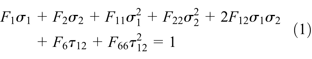
The coefficients

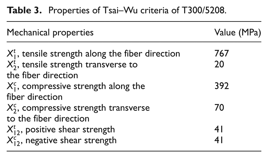
Table 3 shows the mechanical properties of Tsai–Wu criteria of T300/5208. 6
Properties of Tsai–Wu criteria of T300/5208.
The stress state of the lamina calculated by the program is described by the components
The composite ply material directions are shown in Figure 3; direction 1 refers to the ply fiber orientation direction and direction 2 refers to the transverse fiber direction in the plane of the ply.

Composite ply material directions.
Analysis results
Case 1 with stacking sequence [+45°/−45°]4 is taken as an example to show the performance difference; the contour plot of Tsai–Wu strength index under the same torque in opposite direction is shown in Figure 4.

Tsai–Wu failure contour plot: (a) clockwise torque and (b) counter-clockwise torque.
The processed analysis data of all these six cases are shown in Figure 5. Figure 5(a) illustrates that there is an obvious difference in the torsional behavior of composite drive shaft under clockwise torque and counter-clockwise torque. The symmetric laminates of +45° and –45° have little influence on failure coefficient under opposite torque directions, as shown in Figure 5(b). Figure 5(c)–(f) shows that failure coefficients under opposite torque directions are basically the same when 0° and 90° are the outermost layer of the shaft, but they are quite different when 0° is the first layer of the shaft.

The analysis data and comparison: (a) failure indices of Case 1, (b) failure indices of Case 1 and Case 2, (c) failure indices of Case 1 and Case 3, (d) failure indices of Case 4, (e) failure indices of Case 1 and Case 5, and (f) failure indices of Case 3, Case 5, and Case 6.
Conclusion
In this article, the force conditions of composite drive shaft are analyzed with classical mechanics of materials, combining the anisotropic property of composite material; the importance of shaft torque direction in the design of composite drive shaft is proposed. Six stacking schemes are designed and simulated with the FEM in order to explore composite drive shaft’s stacking schemes under the same torque in opposite directions. The Tsai–Wu failure coefficients of shaft under different toque directions are obtained and related data are analyzed. Major conclusions are as follows:
There is an obvious difference in the torsional behavior of composite drive shaft under opposite torque direction. The most obvious one occurs in the lay-up of [+45°/−45°]4, where the failure coefficient of clockwise torque is 1.4–3 times larger than the one of counter-clockwise torque.
The influence on failure coefficients of clockwise and counter-clockwise torque is not obvious when the ply sequence changes from [+45°/−45°]4 to symmetric laminates of [+45°/−45°]2S.
The failure coefficients of clockwise and counter-clockwise torque are nearly identical when 0° and 90° are the outermost layer of the shaft, but the torsional behavior is slightly lower than the one when 45° is the outermost layer of the shaft.
There is no significant difference in failure coefficients between clockwise torque and counter-clockwise torque when 0° is the first layer of the shaft.
Footnotes
Academic Editor: Guoqiang Li
Declaration of conflicting interests
The authors declare that there is no conflict of interest regarding the publication of this article.
Funding
This research was supported by the Significant Science and Technology Innovation Project of Hubei Province, China (Project No. 2014AAA005).