
Abstract
Three-dimensional B-rep is often used to convey product models in computer-aided design, computer-aided engineering, computer-aided process planning, and computer-aided manufacturing systems. Meaningful shape features need to be recognized from the B-rep models for product re-design and manufacturing. In this article, a novel hint-based reusable shape feature recognition approach is presented. Its core objectives include (1) definition and classification of isolated generic shape features by analyzing the shape variation or hint for a Boolean operation in computer-aided design modeling; (2) recognition algorithm for isolated generic shape features by detecting such hints or shape variations for each kind of generic shape feature; and (3) recognition of hybrid generic shape features for complex parts by detecting containing, fusing, and intersecting relationships among available generic shape features. Finally, three engineering parts are used as examples to validate the capabilities of the presented approach.
Introduction
Reusable feature shape recognition is used to extract a group of geometric entities such as faces, edges, or vertices for purposes such as design or manufacturing intents, which can be easily edited or copied as features for efficient shape modeling or manufacturing simulation.1,2 Because feature shape information cannot be easily converted among available computer-aided design (CAD), computer-aided engineering (CAE), computer-aided process planning (CAPP), or computer-aided manufacturing (CAM) systems, basic geometry B-rep models such as IGES or STEP are often used to convert product models. For such geometry-only B-rep models, it is essential to recognize missing features of the converted shapes.
For the geometry-only B-rep models, there are three main feature recognition methods:3–5 graph-based, volume decomposition–based,6–10 and hint-based.11–15 (1) For graph-based approaches, shape features are recognized through sub-graph isomorphism, which is used to find appropriate sub-graphs for the attributed graph built for B-rep models with a given template feature graph.16–24 Although the graph-based methods have been demonstrated to be useful in recognizing some manufacturing feature shapes, such methods depend heavily on attached attributes of graph arcs or nodes, such as convexity, concavity, or tangency of edges and faces, whose inherent ambiguity may make it difficult to uniquely match complex feature shapes. (2) The volume decomposition–based methods of feature recognition, such as convex hull decomposition,6–8 which subdivides the volume of a B-rep model into a set of intermediate convex hulls to recognize features, and cell decomposition,9,10 which decomposes the volume into bounded minimal cells and then combines the cells into volumes and reorganizes these volumes into pre-defined features. However, such volume decomposition based approaches may not be guaranteed to converge because there are so many results. (3) Hint-based feature recognition is based on the fact that manufacturing operations may leave geometry or topology traces on the resulting B-rep model;11–14 it follows a generate-test-repair paradigm to validate the possibility of feature feasibility, which can be used to recognize intersecting features. However, such approaches depend greatly on recognition of each type of manufacturing feature; each feature has its own generate-test-repair algorithm. Verma and Rajotia 15 developed a hybrid feature recognition system combining graph-based and hint-based systems to handle complex interaction features; however, only limited cases can be processed well. In addition, manufacturing feature recognition pays more attention to shapes relating to machine tools and cutters, which may not be sufficient to recognize other kinds of shape features such as design shape features.
In this article, a novel hint-based generic shape feature recognition approach is proposed to achieve the following:
A hint-based general shape feature recognition approach designed to recognize more generic shape features from B-rep models for efficient product re-design, which is based on a common idea: a complex CAD model can be built from an initial basic shape, such as a roughcast, and then sequentially modified by a series of feature operations that will leave typical shape variations such as face splitting, edge collapsing, or vertices missing for the resulting part. Such shape variations can be defined as hints, which can be used to extract more generic shape features without awkward distinction on shape convexity or underlying typical manufacturing processes.
The intersecting feature shapes can also be extracted based on the quantity of hints to obtain more generic shape features for product re-design.
The generic shape feature recognition approach is finally implemented in a prototype system, and three engineering examples are demonstrated to validate the capabilities of the proposed approach and the developed system.
Background of generic shape feature recognition
Shape feature is usually composed of a set of geometric entities that represent specific patterns that may have significance functions or certain manufacturing information. For different domains, the same geometry portion of a CAD model can be defined as different features that may entail different engineering meanings. Nevertheless, from the shape viewpoint, they may have identical characteristics. Therefore, a more generic feature is defined in this article to uniformly describe them.
Definition of generic shape features
During the process of shape modeling, the designers primarily create an initial model that is viewed as a basic shape, such as a sphere, prism, or cylinder, and then sequentially add or remove portions from the basic shape to construct a complex model. The modeling operations will modify the basic shape and generate a series of new geometric entities such as faces, edges, and vertices into the final model. These new geometric entities always correspond to some kind of design or manufacturing intents, which we can call design or manufacturing features. Because only geometric shapes formed by such geometric entities are considered, we uniformly define them as generic shape features.
Definition 1: generic shape feature
A generic shape feature defines a set of geometric entities generated due to modeling operations to represent specific design or manufacturing intents. The generic features emphasize the effects of shape modeling modifying the initial basic shape. The definition of a generic feature is independent of the application domains. Thus, a generic feature can correspond to various types of features for the design and manufacturing domains.
Taxonomy of generic shape features
According to shape variations in geometric entities, there are three kinds of generic features: vertex-class, edge-class, and face-class. As the names suggest, the vertex-class features, edge-class features, and face-class features come from shape variations of vertices, edges, and faces, respectively.
In terms of vertex-class features, the shape modeling operations add or remove vertices from the initial basic shape; hence, the vertex-class feature is also referred to as the vertex elimination feature. Some examples of vertex-class features are shown in Figure 1.

Examples of vertex-class generic features.
Edge-class features are divided into two subclasses because the modeling operations involving edges bring about one of two results: (1) the edge is partitioned partly, and (2) the edge is eliminated completely. The first subclass is called the edge partition feature. The second subclass is called the edge elimination feature. Some examples of edge partition and edge elimination features are shown in Figure 2.

Examples of edge-class generic features.
Face-class features appear complex to classify because the modeling operations involving vertices, edges, and faces could bring about many different results of face variations. In this article, the face-class feature is defined merely as any face alteration except the influences caused by vertex elimination, edge partition, or edge elimination. The face-class feature can be classified into two categories according to different situations of face variations: (1) internal loops are introduced in the face, and (2) the face is partitioned. These two subclasses are referred to as internal loop generic features and face partition generic features, respectively. Some examples of internal loop and face partition features are shown in Figure 3.

Examples of face-class generic features.
The above generic shape features could be isolated or hybrid. An isolated feature is a shape that is independent of other shapes. Hybrid features are characterized as the shapes that are composed of a combination of isolated features. As different isolated features combine, some vertices, edges, or faces may be either removed or partially trimmed or fragmented into different pieces. According to different modes of feature combinations, there are three classes of hybrid generic features: containing hybrid features, fusing hybrid features, and intersecting hybrid features.
A containing hybrid feature is a combination of several small and large isolated features. The small features are called child features. The large features are called parent features. The child features are completely contained by their parent feature and can be individually separated. Some examples of containing hybrid feature are shown in Figure 4(a). A fusing hybrid feature is a combination of several isolated features whose boundaries are fused together. The boundaries may be fusing due to the damage caused by other boundaries or common face sharing by the isolated features. Some examples of fusing hybrid feature features are shown in Figure 4(b). An intersecting hybrid feature is generated by isolated feature intersection. These isolated features are destroyed by each other. Thus, they cannot be separated and recognized directly. Some examples of intersecting hybrid feature features are shown in Figure 4(c).
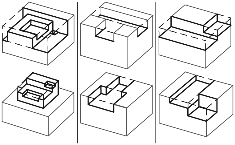
Examples of hybrid generic features: (a) containing hybrid feature, (b) fusing hybrid feature, and (c) intersecting hybrid feature.
Finally, the taxonomy of generic features, including isolated and hybrid features, is shown in Figure 5.

Taxonomy of generic features.
Correspondences between generic shape features and design or manufacturing features
Because the proposed generic features are defined based on the shape variations of modeling operations and independent of any specific knowledge, they could correspond to most common types of design and manufacturing features.
The common design and manufacturing features could both be classified into three categories: normal features, transitional features, and surface features. Normal design features refer to the convex and concave portions in a CAD model that are generated by extrude, revolve, sweep, and loft operations. Normal manufacturing features refer to the faces generated by common manufacturing operations such as slots, steps, and holes. Transitional design features refer to the transition regions in a CAD model that are generated by chamfer and fillet operations. Transitional manufacturing features refer to the faces generated by trimming and blending. Surface features refer to the special surfaces that do not belong to any class of normal or transitional features. Figure 6 shows the examples of design and manufacturing features.
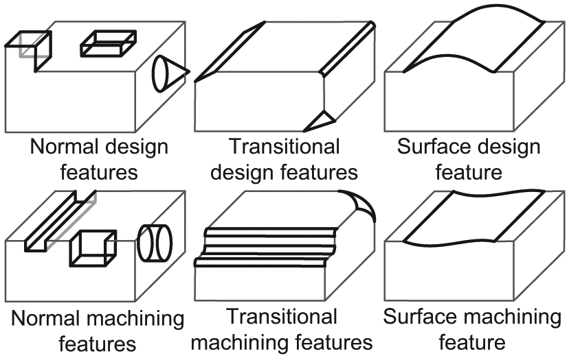
Examples of design and manufacturing features.
The major difference between design and manufacturing features is that a design feature could be a convex portion, but the term “manufacturing feature” only refers to a removal of volume, that is, the concave portion. However, obviously, the generations of these features must result in several shape variations. Therefore, the design and manufacturing features could correspond to certain classes of generic features. For example, a conical boss is an internal loop generic feature and also a normal design feature; a step is an edge partition generic feature and also a normal manufacturing feature; a spline surface is a face partition generic feature and also a surface design/manufacturing feature. The correspondences between generic features and design/manufacturing features are summarized in Figure 7.

Correspondences between generic features and design/manufacturing features.
Generic shape feature recognition problem and recognition bases
Generic shape feature recognition is typically used to efficiently re-design the product model. Because the faces can allow users complete control over feature shapes that must be recognized, and each isolated generic shape feature is related to one or more faces, the initial input of generic shape feature recognition is in the form of faces (referred to as

where
Definition 2: FEG
FEG represents the structure of faces and edges of a 3D shape. A node in the FEG indicates a face, and an arc between two nodes indicates the corresponding edge shared by the two faces.
Definition 3: VEG
VEG represents the structure of vertices and edges of a 3D shape. A node in the VEG indicates a vertex, and an arc between two nodes indicates the edge adjacent to the two vertices. Moreover, to determine the appropriate search field in FEG, the concept of a face level must be defined.
Definition 4: face level
The shortest distance in FEG from the input face to a node is defined as the level of that node. For instance, if the input is Face a, the levels of the nodes around Face a are shown in Figure 8. The procedure of feature recognition triggers from the closest to the remotest level and proceeds until finding the faces expected to be able to constitute the generic feature.
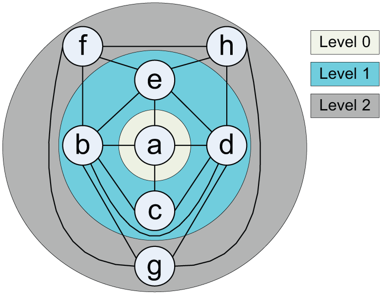
Face level around Face a in FEG.
Based on FEG, VEG, and face level, the recognition methods for vertex-class, edge-class, and face-class generic features are illustrated, respectively.
Recognition of isolated generic features
Based on FEG, VEG, and face level, the recognition methods for vertex-class, edge-class, and face-class generic features are illustrated, respectively, below.
Recognition of vertex-class generic features
A simple example of a vertex elimination feature and its FEG and VEG is shown in Figure 9, to help analyze the characteristics of vertex elimination features in detail. As shown in Figure 9, when Vertex 1 is removed, Faces g and h will emerge and compose a vertex elimination feature. The removing modification will change Faces a, b, and c and Edges 1-2, 1-4, and 1-5 that share Vertex 1. These changed faces and edges are the hints of the vertex elimination feature.
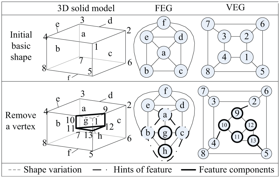
Example of vertex elimination feature recognition.
Due to the altered appearance of the initial basic shape, the vertex elimination feature can be characterized by a set of faces that satisfy the following requirements: (1) they are adjacent to each other, (2) they do not intersect at a vertex, and (3) the extensions of the shared edges between them could intersect at a vertex. The hint manifests that a set of nodes adjacent to each other in FEG, although they have corresponding linking arcs in VEG, do not intersect at one node.
The brief pseudo-code for vertex elimination feature recognition is as follows:
Step 1. Input face
Step 2. Find the nodes
Step 3. For the arcs between the nodes in
Step 4. For each arc in
Step 5. If the
Recognition of edge-class generic features
Edge partition feature recognition
For the recognition of edge partition generic features, a simple example in Figure 10 is used to interpret it. Owing to the modeling operation of edge partition, the edge between Faces a and b is partitioned into two parts, introducing Faces g, h, and i, which comprise an edge partition feature. Subsequently, Faces a and b and their shared edges constitute the hints of the feature.

Example of edge partition feature recognition.
In summary, the edge partition feature can be characterized by the hint of a pair of adjacent faces that share two or more edges, namely, a pair of nodes linked by two or more arcs in FEG.
The brief pseudo-code for edge partition feature recognition is as follows:
Step 1. Input face
Step 2. Find two nodes
Step 3. Find the nodes {FeatureNodes} in FEG surrounded by
Step 4. If the
Edge partition feature recognition
If an edge is eliminated completely, the removed edge will cause a shape variation that could include vertex elimination and face alternation. In the case shown in Figure 11, after the edge adjacent to both Faces a and b is eliminated, Faces a, b, c, and e relevant to the edge change to some extent. Moreover, any conceivable combination triplet of Faces a, b, c, and e does not intersect at a vertex. The changed Faces a, b, c, and e are the hints of the edge elimination feature. Subsequently, Face g comprises the feature.

Example of edge elimination feature recognition.
The edge elimination feature can be characterized by the hint that a succession of adjacent faces and any triplet of them would not intersect at a vertex, namely, a series of nodes in FEG that link end-to-end.
The brief pseudo-code for edge elimination feature recognition is as follows:
Step 1. Input face
Step 2. Find a series of nodes
Step 3. If more than three nodes belong to
Step 4. If the
Recognition of face-class generic features
Internal loop feature recognition
A typical example of an internal loop feature is shown in Figure 12. In this case, Face f is the face that is introduced as an internal loop and the generated Face g constitutes a simple boss. Face g constitutes the internal loop feature; Face f and its internal loop constitute the hints.

Example of internal loop feature recognition.
In short, an internal loop feature is characterized by being attached to a basic shape through one or more internal loops. Therefore, by detecting the hint of internal loops, the FEG is decomposed into several sub-graphs from the arcs corresponding to the internal loops. The faces in the sub-graph that involve the input face are regarded as relatively independent; hence, they could constitute the internal loop generic feature.
Face partition feature recognition
According to the face partition features, faces are split into two or more parts. A simple example of a face partition feature is shown in Figure 13. As a result of face partition, Face a is split into two parts: Faces a and g. Subsequently, Faces h, i, and j, located between Faces a and g, constitute a groove. Faces h, i, and j constitute a face partition feature, and Faces a and g are the hints.

Example of face partition feature recognition.
In summary, after face splitting, the remaining faces could share the same surface, which leaves a hint for feature recognition. Thus, the face partition feature can be characterized by the hint that several faces share the same surface, and the faces between the hint faces are candidates to be the feature.
The brief pseudo-code for face partition feature recognition is as follows:
Step 1. Input face
Step 2. Find a set of nodes
Step 3. For each pair of nodes in
Step 4. If the
Recognition of hybrid generic features
When several isolated generic features are combined, a hybrid feature shape will be formed. Section “Background of generic shape feature recognition” gives the three modes of hybrid generic feature. This section illustrates the recognition process for various hybrid generic features.
First, the concept of identifying order shall be defined. During the procedure of hybrid feature recognition, the face internal loop feature is easily identified because only one hint face is required. Hence, it is identified first. Two hint faces are required for edge partition feature recognition so that it is identified second. Three hint faces are required for vertex elimination feature recognition so that it is identified third. The recognitions of face partition features and edge elimination features require at least four hint faces. However, several hint faces for face partition feature recognition share an identical geometric surface; thus, a face partition feature is identified before an edge elimination feature. Based on the above conclusions, the five classes of generic features should be identified from hybrid features in the following order

Recognition of containing hybrid feature
In a containing hybrid feature, the contained child features are recognized independently of the parent feature. When a child feature has been recognized, its corresponding nodes should be removed from its parent feature; the parent feature then consists of the remaining nodes.
The steps of containing hybrid feature recognition are designed as follows:
Step 1. Input face
Step 2. Find the hints of the features from
Step 3. Find the nodes {FeatureNodesi} in FEG located among the nodes of
Step 4. If the
Step 5. In the nodes of {FeatureNodes}, repeat Steps 2–4 to individually find the child features within the hybrid feature. When a child feature is found, it will be completely separated from the parent feature.
An example of containing hybrid feature recognition is shown in Figure 14. First, an internal loop feature composed of Faces g–t is recognized as the parent feature. Then, an edge partition feature consisting of Faces n–q, a vertex elimination feature consisting of Faces r–t, and an edge elimination feature consisting of Faces l and m are identified and separated from the parent feature. Finally, the remaining Faces g, h, i, j, and k are considered as the components of the internal loop feature.
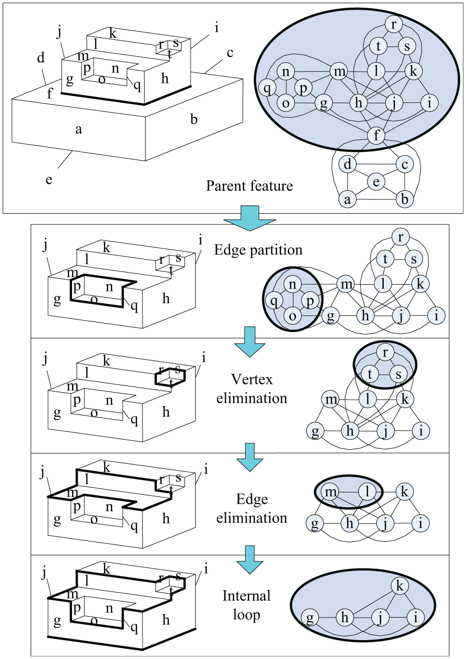
Example of containing hybrid feature recognition.
Recognition of fusing hybrid features
If a fusing hybrid feature can be recognized by the accumulated hints, it will be recognized directly. Otherwise, the isolated features recognized later will be fused into the feature recognized earlier to generate a fusing feature. The steps of fusing hybrid generic features are designed as follows:
Step 1. Input face
Step 2. Find the hints of the features from
Step 3. Find the nodes {FeatureNodes} in FEG located among the nodes of
Step 4. If the
An example of fusing hybrid feature recognition is shown in Figure 15. An edge partition feature is composed of Faces h, i, j, k, and l. A face partition feature is composed of Faces i, m, and n. Face i is shared by edge partition feature and face partition feature so that they are fused together to form a unified face partition feature. Based on the fact that Faces f and g share a common surface, this new face partition feature could be recognized as an isolated generic feature.
Example of fusing hybrid feature recognition.
Recognition of intersecting hybrid features
In intersecting hybrid features, several isolated features intersect with each other so that some features may be destroyed and cannot be recognized directly. To recognize the destroyed features, an intermediate step of feature extraction and FEG mending is needed. After an isolated feature is recognized, it will be extracted from the hybrid feature, and then the FEG of the hybrid feature will be amended according to the following rules:
If the extracted feature is an edge elimination feature, the nodes of the faces that share the eliminated edge are linked by an arc.
If the extracted feature is a face partition feature, its hint faces are merged into a new face and the nodes linked with these hint faces are re-linked to the new face.
If the extracted feature is an edge partition feature, the multiple arcs linked to the nodes of the hint faces are merged into one arc.
If the extracted feature is a vertex elimination feature or an internal loop feature, the nodes of this feature are directly extracted from the FEG.
This intermediate step attempts to repair the damaged features to reduce their influence on feature recognition. This process will be repeated until all child features have been recognized.
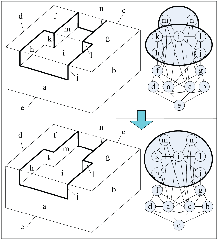
An example of intersecting hybrid feature recognition is shown in Figure 16. In this example, face l is damaged because of the intersection of a vertex elimination feature and a face partition feature. To recognize the vertex elimination feature, the face partition feature will be recognized and extracted from the model and Faces f and g will be merged into Face n to mend FEG. Then, based on Faces n, a, and b, the vertex elimination feature consisting of Faces k, l, and m will be identified.

Example of intersecting hybrid feature recognition.
Implementation and validation
Based on the approach presented above, a prototype system for generic shape feature recognition from B-rep CAD models is developed using the 3D ACIS Modeler. 25 This prototype system is then validated with some B-rep product models.
Figure 17 illustrates the results of the experiments for the main classes of generic feature recognition, including isolated and hybrid features. The faces constituting the features are highlighted in light green. The vertex elimination, edge partition, edge elimination, face partition, and internal loop features are abbreviated as V-E, E-P, E-E, F-P, and I-L, respectively.

Experiments of generic shape feature recognition.
Next, applications of the proposed approach to three engineering models are exhibited. The first model is an ordinary mechanical part. Some depressions and cylindrical bosses are recognized from the part as face partition, edge elimination, and internal loop generic features. The 3D shape of this model and the features recognized from this model are shown in Figure 18.

The first engineering model.
The second model is taken from the literature. 26 The main classes of generic features are contained in this model (see Figure 19), including face partition (No. 1, 14, etc.), internal loop (No. 2, 20, etc.), vertex elimination (No. 5, 43, etc.), edge partition (No. 9, 24, etc.), and edge elimination features (No. 18, 42, etc.). The manufacturing features recognized in the literature 26 all correspond to these generic features; some additional types of design and manufacturing features (Nos 18, 19, 32, 42, etc.) also could be recognized by the approach represented in this article.

The second engineering model.
The third model is a benchmark presented in the literature. 27 The 3D shape of this model is more irregular, and some intersecting hybrid features are included. Therefore, the feature recognition from the third model needs some indirect steps. As shown in Figure 20(a), the fillet, blend, holes, and grooves will be directly recognized as edge elimination, internal loop, and face partition features. Then, these features are extracted from the model, and some generic features will be recognized indirectly as shown in Figure 20(b). By this procedure, the problem of interacting feature recognition could be solved effectively.

The third engineering model.
Discussion
For the generic feature recognition algorithm above, in this section, we need to evaluate its computational complexity and limitations of the present algorithm.
Computational complexity
Let
Limitations
As described above, it is essential to decompose a hybrid feature into generic shape features, when possible, for efficient shape design. Available hybrid feature decomposition methods such as containing, fusing, and intersecting hybrid features can only process limited shapes, which may lead to some shapes being left as a hybrid feature. Therefore, a more effective decomposition algorithm needs to be found to enable decomposition of complex shapes into more meaningful generic features for efficient re-design.
Conclusion
During the data exchange process between various CAD, CAE, and CAM systems, CAD models with B-rep only are often utilized, and the feature-related information may not be included. However, such meaningful feature shape information is essential for the following product development or manufacturing process. To recognize such feature information from the B-rep-only CAD models, a novel approach for generic feature recognition was presented in this article. The shape variations or hints emerging during the modeling operations on vertices, edges, and faces were traced and collected to obtain generalized properties of the features for generic feature recognition. With this solution, various design and manufacturing features of practical industrial parts can be recognized as generic features for downstream applications. Furthermore, the interacting features can also be recognized as containing, fusing, and intersecting hybrid generic features of a complex shape. The approach was finally implemented on a prototype system. Some experiments and three case studies demonstrated that the approach can be efficiently used to recognize the generic shape features from the B-rep CAD models for shape re-design and manufacturing process planning.
Footnotes
Academic Editor: John T Smith
Declaration of conflicting interests
The authors declare that there is no conflict of interest.
Funding
This work was partially supported by the National Natural Science Foundation of China (Nos 51375185, 51405177, and U1430124) and National High Technology Research and Development Program of China (863 Program, No. 2013AA041301).