
Abstract
A numerical investigation into the initial stress distribution induced within the periodontal ligament by thermoplastic appliances with different thicknesses is performed. Based on the plaster model of a 25-year-old male patient, a finite element model of the maxillary lateral incisors and their supporting structures is constructed. In addition, four finite element models of thermoplastic appliances with different thicknesses in the range of 0.5–1.25 mm are also constructed based on the same plaster model. Finite element analysis simulations are performed to examine the effects of the force delivered by the thermoplastic appliances on the stress response of the periodontal ligament during the elastic recovery process. The results show that the stress induced in the periodontal ligament increases with an increasing appliance thickness. For example, the stress triples from 0.0012 to 0.0038 MPa as the appliance thickness is increased from 0.75 to 1.25 mm. The results presented in this study provide a useful insight into as a result of the compressive and tensile stresses induced by thermoplastic appliances of different thicknesses. Moreover, the results enable the periodontal ligament stress levels produced by thermoplastic appliances of different thicknesses to be reliably estimated.
Introduction
The periodontal ligament (PDL) forms part of the periodontium, which comprises the alveolar bone, the dental cementum, and the gingiva, and is designed both to protect the teeth and to fix them to the maxillary or mandibular bones. Orthodontic appliances are commonly used to achieve therapeutic tooth movement by inducing a mechanical stress in the alveolar bone. 1 It is generally accepted that the PDL plays a key role in determining the tooth movement which occurs in response to an applied mechanical stress. Thus, in developing effective orthodontic treatments, it is necessary to understand the relationship between the force delivered by an orthodontic appliance and the corresponding stress induced within the PDL and surrounding structures. In practice, this is most easily achieved by means of finite element analyses (FEAs). 2
Thermoplastic appliances have excellent esthetic characteristics and provide an effective means of achieving tooth movement.3,4 Compared to conventional fixed appliances based on brackets and wires, thermoplastic appliances have several important advantages, including near invisibility and the potential to remove and reset the appliance as required at different stages of the therapeutic treatment.5,6 A previous study showed that cases treated with an Invisalign appliance showed a lower objective grading system (OGS) passing rate than those treated with conventional fixed appliances. 7 Moreover, Kuncio et al. 6 found that 83% of the patients showed full appliance acceptance after 1 week, while 54% reported no pain after 2–3 days.
Barbagallo et al. 8 investigated the force imparted by thermoplastic appliances to the first maxillary premolars using a pressure film approach. Hahn et al.9–11 measured the force delivery properties of thermoplastic appliances with different thicknesses and materials during tipping and intrusion. Various researchers have evaluated the force and energy-delivering properties of orthodontic thermoplastic devices by means of three-point bending recovery tests. 12 Furthermore, Kohda et al. 13 performed nanoindentation tests to evaluate the orthodontic forces delivered by thermoplastic appliances fabricated with different materials, thicknesses, and activation amounts.
However, despite the contributions of the above-mentioned studies, the actual biomechanical phenomena induced by thermoplastic appliances during orthodontic treatment are still relatively unclear. The intensity of the initial stresses induced by thermoplastic appliances due to their elastic recovery has not been introduced in the previous simulation models. Accordingly, using a realistic model of the maxillary lateral incisors and their supporting structures, this study performs a series of FEA simulations to investigate the stress distribution induced within the PDL by thermoplastic appliances with four different thicknesses. The results show that the elastic recovery stresses could be properly adjusted by appliance thickness to control tooth movement.
Materials and methods
An impression of the maxillary lateral incisors of a 25-year-old male patient using a silicone rubber material (Dent Silicone V; Premiere, Taipei, Taiwan) was made. The cast was poured immediately using a vacuum spatulated high-quality dental stone (CRK-35; KUANG PANG GYPSUM, Hsinchu, Taiwan) and allowed to dry overnight. The amount of activation (0.25 mm) required to account for bodily movement was adjusted using the silicone rubber impression material itself and spacers (small pieces of thermoplastic material with thicknesses ranging from 0.5 to 1.25 mm) placed between the labial surface of the impression and the dissected lateral incisor, attached to the impression with glue, and then fixed in place with high-quality dental stone. Thermoplastic appliances with four different thicknesses (i.e. 0.5, 0.75, 1, and 1.25 mm) were made using a pressure-molding machine (BIOSTAR; Scheu-Dental GmbH, Iserlohn, Germany). The plaster model and thermoplastic appliances were scanned using a three-dimensional (3D) optical measurement system (COMET 5; Steinbichler Optotechnik, Munich, Germany). The dental data were obtained by means of eight scans separated by 45° and were then combined into a single 3D model using Geomagic Studio software (Geomagic, Morrisville, NC, USA).
Construction of 3D finite element model
The proposed finite element (FE) model of full teeth was constructed based on the dimensions and morphology of tooth, PDL, and bone from a cadaver shown in a standard dental anatomy textbook. 14 The mean value used in the literature, a thickness of 0.2 mm, was assumed for the PDL. 15 The dimensions of the PDL and supporting structures in the 3D model were identified using SolidWorks software (version 2013; Dassault Systèmes Corp., Waltham, MA, USA). The 3D model was then converted to a parasolid format using Abaqus FE software (version 6.12; Dassault Systèmes Corp.). The FE model as shown in Figure 1 contained a total of 685,768 ten-node tetrahedron elements: 138,568 ten-node tetrahedron elements for the thermoplastic appliance, 166,744 ten-node tetrahedron elements for the teeth, 297,685 ten-node tetrahedron elements for the alveolar bone, and 82,771 ten-node tetrahedron elements for the PDL. Note that both the teeth model and the thermoplastic appliances were meshed 10-node quadratic tetrahedron elements.

Finite element model of maxillary segment with alveolar bone, periodontal ligament (PDL), teeth, and thermoplastic appliance. The PDL is modeled as the space between the alveolar bone and the tooth roots.
Material properties
In performing the simulations, the teeth, bone, PDL, and thermoplastic appliances were assumed to be fabricated of homogenous and isotropic materials with a uniform Young’s modulus. Note that even though the PDL does, in fact, consist of a nonlinear viscoelastic material, the present assumptions are valid since previous studies have shown that both the type of tooth movement and the strain distribution within the PDL are insensitive to material nonlinearities. 16 The material properties for the PDL and other dental components are summarized in Table 1.
Material properties used in finite element analysis (FEA) simulations. a
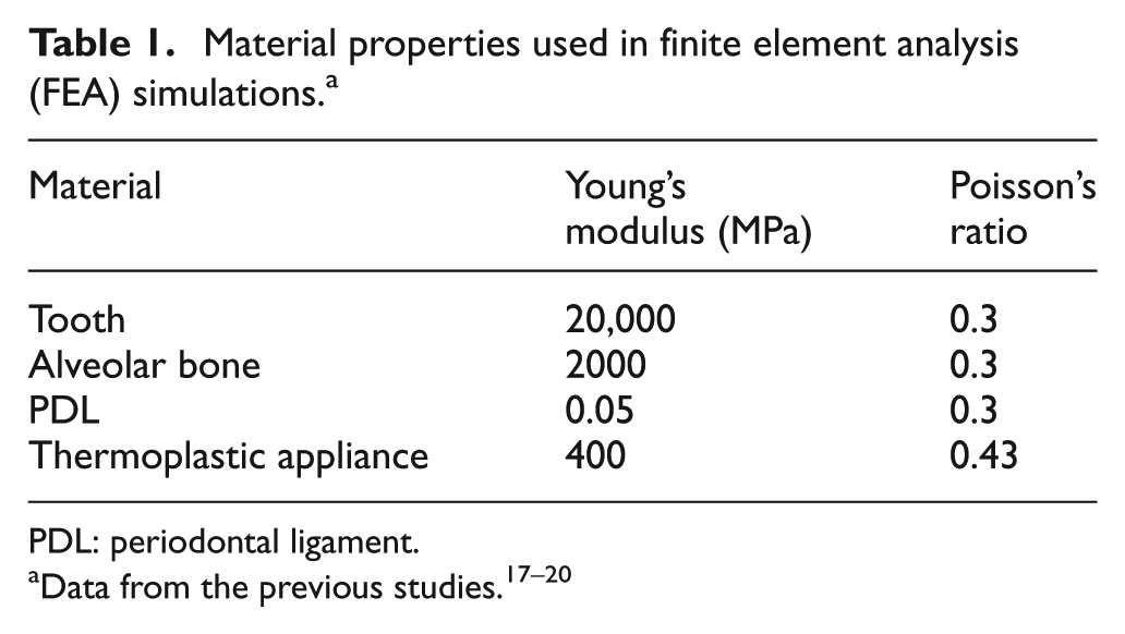
PDL: periodontal ligament.
Boundary conditions and contact mode
To obtain accurate solutions for the stress distribution within the PDL and alveolar bone, the contacts between the PDL and teeth and PDL and bone, respectively, must be appropriately defined. Fixed boundary condition was provided by restraining all degrees of freedom for the surface of the bone. The number and type of constraints for each component are listed in Table 2. Thus, in the present Abaqus simulations, the contacts between neighboring bodies were modeled using the small-sliding surface-to-surface contact mode, in which small-scale sliding between the two bodies is permitted, but arbitrary rotations of the bodies are not allowed. Furthermore, in imposing the boundary conditions in Figure 1, none of the degrees of freedom were constrained for the nodes comprising the teeth and PDL, whereas all of the degrees of freedom were constrained for the nodes comprising the alveolar bone.
Contact settings used in finite element analysis (FEA) simulations.

PDL: periodontal ligament.
Loading conditions
Since the entire FE model in Figure 1 contained numerous elements, directly simulating the appliance moves slides on the teeth surface was time-consuming and difficult to converge. Therefore, two simulation stages were employed to complete the analysis, as shown in Figure 2. In the first stage, the teeth model was treated as a rigid body, the appliance model constrained the nodes only at the bottom location at Z0, and the contact interface was established between the appliance and the tooth surface; the simulation was performed to simulate constrained nodes move up to Z1 (gum). The contact stresses in the appliance model could then be exported as an Abaqus prestress subroutine that could be imported into the next-stage simulation model as appliance initial stresses (preload).

(a) First finite element (FE) model simulation stage and (b) second FE simulation stage.
In performing the second simulation stage, the full FE model, including the appliance on the tooth surface, was applied to study how preload occurred in appliance transferred into PDL. Abaqus can initialize the prestress from the results based on the first simulation stage for the appliance. The contact analysis between the appliance and the full teeth model was performed to transfer initial stresses from the appliance into the teeth until force equilibrium was reached for the entire model. Regions A1 and A2 of the PDL are expected to undergo tissue compression during the relaxation of the thermoplastic appliance, regions B1 and B2 undergo tension, and region C1 undergoes compression and tension. 21 By applying this second simulation stage, we could examine the stresses in PDL with various appliance thicknesses.
Results
Following its fitting, the thermoplastic appliance constrains the direction of tooth movement as it undergoes elastic recovery. This constraining effect generates an accumulation of stress within the PDL and surrounding structures, as shown in Figure 3. In snapshots A and B, showing the case where the appliance is first fitted, stress is generated in the tooth. In snapshots C and D, the stress delivered to the PDL root neck increases, while that delivered to the tooth center reduces. In snapshot E, the stress generated in the surrounding bone reduces significantly. Finally, in snapshot F, the model reaches equilibrium conditions and stress delivery ceases.
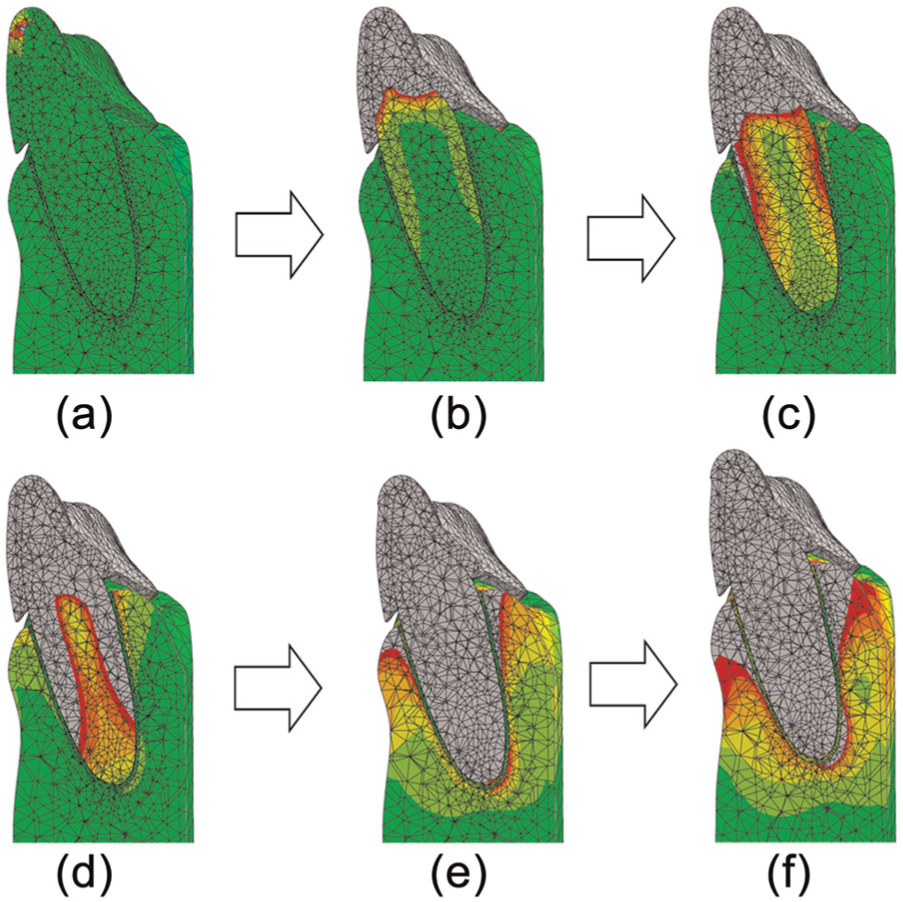
Simulation snapshots showing stress delivered to tooth, periodontal ligament (PDL), and surrounding bone structure during elastic recovery of thermoplastic appliance.
Figure 4 shows the magnitude of the initial stress acting at various points of the PDL as a function of the thermoplastic appliance thickness. It is seen that for all values of the appliance thickness, a tensile stress is generated between regions A and B and C and D, respectively, while a compressive stress is generated in all other regions. In addition, it is observed that for the minimum appliance thickness of 0.5 nm, the tensile and compressive stresses have an extremely low and constant magnitude of approximately 0.0001 MPa. However, as the appliance thickness increases, the intensities of the tensile and compressive stresses also increase. For example, given an appliance thickness of 0.75 mm, the maximum tensile stress has a value of 0.0012 MPa, while the maximum compressive stress has a value of 0.0012 MPa. Similarly, for an appliance thickness of 1.25 mm, the maximum tensile stress is almost 0.0035 MPa, while the maximum compressive stress is around 0.0038 MPa.

Distribution of stress intensity in periodontal ligament (PDL) from labial (A) to lingual (E) connections as a function of thermoplastic appliance thickness.
Figure 5 shows the stress contours in the PDL model given the use of the four different thermoplastic appliances. It is seen that appliance thicknesses of 0.5–1.0 mm result in only minor tensile and compressive stresses. However, given the maximum appliance thickness of 1.25 mm, significant tensile and compressive stresses are induced in the PDL root neck and root apex regions, respectively. The tooth is not only displaced in the direction of the force but also rotated around the center of resistance for tipping tooth movement.

Stress contours within periodontal ligament (PDL) and teeth as a function of appliance thickness. Tensile stresses (blue) are induced on the side at which the orthodontic load is applied, and compressive stresses (red) are induced on the opposite side.
Discussion
This study has performed FEA simulations to investigate the stress distribution within the tissues surrounding orthodontically loaded teeth. It had undergone tissue compression and tension. Most early FEAs confirmed the results of traditional pressure–tension theory. 22 In general, the models used in these investigations failed to take into account the true anatomy and physical properties of the periodontium. However, recent studies have shown that the load transfer mechanism from the teeth through the PDL to the alveolar support structure is strongly dependent on both the material properties of the various periodontal tissues and the (micro)morphology of the periodontium. 2 Thus, in the model used in this study, the material properties (i.e. Young’s modulus and Poisson’s ratio) of the tooth, PDL, and alveolar bone must be considered in order to ensure the accuracy of the numerical results.
Orthodontically induced inflammatory root resorption is associated with a local compression of the periodontal membrane. 23 Moreover, Kanzaki et al. 24 hypothesized that PDL cells under mechanical stress play a pivotal role in orthodontic tooth movement. Figure 5 shows that the region over which a thermoplastic appliance initially delivers stress expands as the appliance thickness increases. In addition, the tensile and compressive stress response shown in Figure 5 is consistent with the PDL tissue response described in the literature. 25 It has been reported that the optimal time for wearing thermoplastic appliances is 2 weeks; during which time, the teeth are typically under treatment for approximately 21–23 h each day. 26 However, different patients may experience PDL movement for different durations. Moreover, the effective force application threshold is approximately 6 h; force duration and magnitude are important factors in tooth movement. 27 Lee 28 suggested that the maximum PDL stress level should not exceed 0.026 MPa. It is noted that these guidelines are consistent with the maximum stress observed in this study given a thermoplastic appliance with a thickness of 1.25 mm.
The biological structures of the teeth and PDL are very complex. Thus, the present simulations have been performed using a simplified FE model. Nonetheless, the results obtained using the model provide a useful insight into the evolution of the stress distribution within the tooth and PDL over the orthodontic treatment process (Figure 3). In utilizing the resilience of a thermoplastic appliance to generate orthodontic stress, sufficient time and surface area are required to maintain and extend stress delivery. Moreover, the optimal force is that which elicits the maximum cellular response while still maintaining tissue vitality. If insufficient force is delivered to the target tooth, tooth movement may simply not occur. Conversely, if excessive force is applied, indirect rather than direct bone resorption may occur, and thus, the tooth movement speed is reduced. 29 The simulation results obtained in this study have shown that the tensile and compressive stresses induced by a thermoplastic appliance with a thickness of 0.75 mm are only slightly higher than those generated by an appliance with a thickness of 0.5 mm. However, the magnitude of the induced stress increases approximately threefold as the appliance thickness is increased from 0.75 to 1.25 mm (Figure 4). These findings are consistent with the results of previous studies, which showed that thicker thermoplastic appliances deliver more desirable forces than thinner ones. 9 In general, the results presented in this study suggest that in designing thermoplastic appliances for orthodontic treatment, the orthodontist should consider not only the position at which the stress should be applied in order to generate the required movement direction but also the thickness of the appliance which is necessary to generate a driving force of sufficient intensity.
Conclusion
This study has successfully developed a series of FEA that actually simulate the elastic recovery of the appliance and obtained the contact stresses as the initial loading to the tooth FE model. The stresses in PDL were investigated with various appliance thicknesses ranging from 0.5 to 1.25 mm. The tooth movement induced by thermoplastic appliances is strongly correlated with both the intensity and the distribution of the stress within the PDL. The intensity of the tensile and compressive stress induced by a thermoplastic appliance is strongly related to the appliance thickness. For example, in the model considered in this study, the magnitude of the maximum induced stress triples from approximately 0.0012 MPa (given an appliance thickness of 0.75 mm) to approximately 0.0038 MPa (given an appliance thickness of 1.25 mm). In other words, the appliance thickness must be carefully specified in order to achieve the orthodontic environment required to generate the optimal tooth movement over time.
Footnotes
Academic Editor: Shan-Tung Tu
Declaration of conflicting interests
The authors declare that there is no conflict of interest.
Funding
This work was financially supported by the Ministry of Science and Technology of Taiwan, R.O.C., under grant nos NSC100-2221-E-194-018 and NSC 101-2221-E-194-014-MY3.