
Abstract
When a soft polishing tool is compressed on a stiff workpiece of curved surface, the contact area is a piece of the curved surface. In the process of aspheric surface polishing, the machining speed is always provided by the rotational speed of the spindle of a computer numerical control lathe. Yet, the polishing tool is usually made rotating to remove cutting scraps and broken abrasives from the contact area. The rotational speed of the polishing tool would change the distribution state of the relative speed in the whole contact area, and it would definitely change the volume of material removal in the surface of the workpiece. This article studies how the rotational speed of the polishing tool changes the distribution state of the relative speed in the whole contact area and material removal in the volume of the surface of the workpiece. The computing results show that the volume of material removal increases with the increase in both the rotational speed of polishing disk and the rotational speed of lathe spindle, but the polishing quality is totally not in this case.
Introduction
Aspheric optics are always of extremely high shape precision and low surface roughness, which are widely used in the military field, the aeronautics and astronautics field, and some high-tech fields. These workpieces usually have to be polished to reach ultra-smooth surfaces at nano-scale.1–3 After they have been shaped by advanced computer numerical control (CNC) lathes, aspheric optics still need to be polished to reduce surface quality and improve shape precision.4,5 Based on the geometric characteristics, the CNC equipments on aspheric surface compliant polishing still have all the same essential functions as ordinary CNC lathes.6–8 By the existing theories on curved surfaces compliant polishing, the polishing process is controlled by adjusting the product of normal contact force, relative speed, and machining time.7–9 When a workpiece of aspheric surface is machined with ordinary CNC lathes, the cutting speed, that is, the above relative speed, is the same as the rational speed of the spindle of the machine tool. Theoretically, polishing tools, including polishing wheels and polishing disks, do not have to rotate, and the workpiece could definitely be shaped and polished. But in reality, polishing tools are always made to rotate to keep a good condition for abrasive.10–12 If the polishing tool is made static, this tool will always have the same area keeping contact with the workpiece, and thus, the contact area would be filled with cutting scraps, broken abrasives, and polishing paste in a few minutes.9–11 In such case, the workpiece cannot be polished any more.
Based on kinematics, when the polishing tools obtain a rotational speed, the relative speed would be changed because the relative speed is the resultant speed of the rotational speed of workpiece and the rotational speed of polishing tool.13,14 If the polishing tool rotates faster, it would play the dominant role especially in the center of workpiece where the rotating radius is small. But this is totally not the case on the edge of the workpiece. Moreover, if the workpiece is a large one in size, a large polishing disk would be needed, as large workpieces always obtain more unneeded materials needed to be polished, and hence, large polishing disks could remove material much more efficiently. By the way, large polishing disks could effectively eliminate surface chatter marks caused by the high-frequency vibrations of the tool system, so they could significantly improve the surface’s quality and have been widely used in large aspheric optics polishing. But when a large aspheric optic of large curvature is polished by a large soft polishing disk, how the rotational speed of the disk changes the polishing process has achieved worldwide admiration and interest down to present time. Changed relative speed would result in changed material removal.10–12 It is generally believed that it is the convolution of the rotational speed of polishing disk and the rotational speed of the spindle of lathe that dominates the curved surface polishing process. But for the large surface of large curvature, the resultant speed would have a component in the normal direction at the cutting point and no longer lies in the tangent plane of working point, so the traditional convolution algorithm could not describe the relationship between the rotational speed of polishing disk and the rotational speed of the spindle of lathe. No research work has been done on how the machining speed has been changed for the large aspheric surface with large curvature yet; therefore, we shall study how the material removal would be changed for the same. In this article, the kinematics model is established based on the deformation analysis of soft polishing disk in the vector space, the relationship between the material removal process and the relative rotational speed is built, and how the removal process is affected by the rotational speed of polishing disk are studied. The computing results show that the volume of material removal increases with the increase in both the rotational speed of polishing disk and the rotational speed of lathe spindle, but the polishing quality is totally not in this case.
Kinematics model
When an aspheric part is polished with a CNC lathe, the machine tool has its accredited coordinate system. For the sake of simplification, define a coordinate system of

Kinematics model of aspheric surface polishing with soft pads: (a) 2D model and (b) 3D model.
Define
Define

Computing method
In equation (1), all variables are vectors which should be described by both values and directions. All the values and directions are determined by the location of the cutting point
Computing method of
In Figure 1(b),

So

In the above two equations,
Computing method of
In Figure 1(b),

The right direction of u-axis is exactly the right directions of the grad at the cutting point

And the projected vector of u-axis could be defined by 15

where
Suppose the machined aspheric surface is an ellipse, which could be defined by

where

Computing method of
and
Let


According to (5)

Relative speed computing
For the sake of flexibility and efficiency, the polishing tool would be shaped as a disk, and it is usually very soft and thick, so that it would contact with the workpiece with its whole area when it is compressed by an average normal force

When

Curves of
Influence of
on material removal
Based on the most accepted Preston polishing theory and other studies,
9
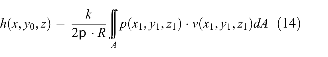
the volume of material removal at a single point is just in direct proportion to the product of the contact stress in the normal direction, the machining time, and the relative speed between the polishing tool and the workpiece at the machining point. Define

where
In the process of compliant polishing, the speed of feed movement is always much more lower than the cutting speed. In this way, any single point in the machined surface would be polished again and again. When the aspheric surface rotates around the y-axis,
where
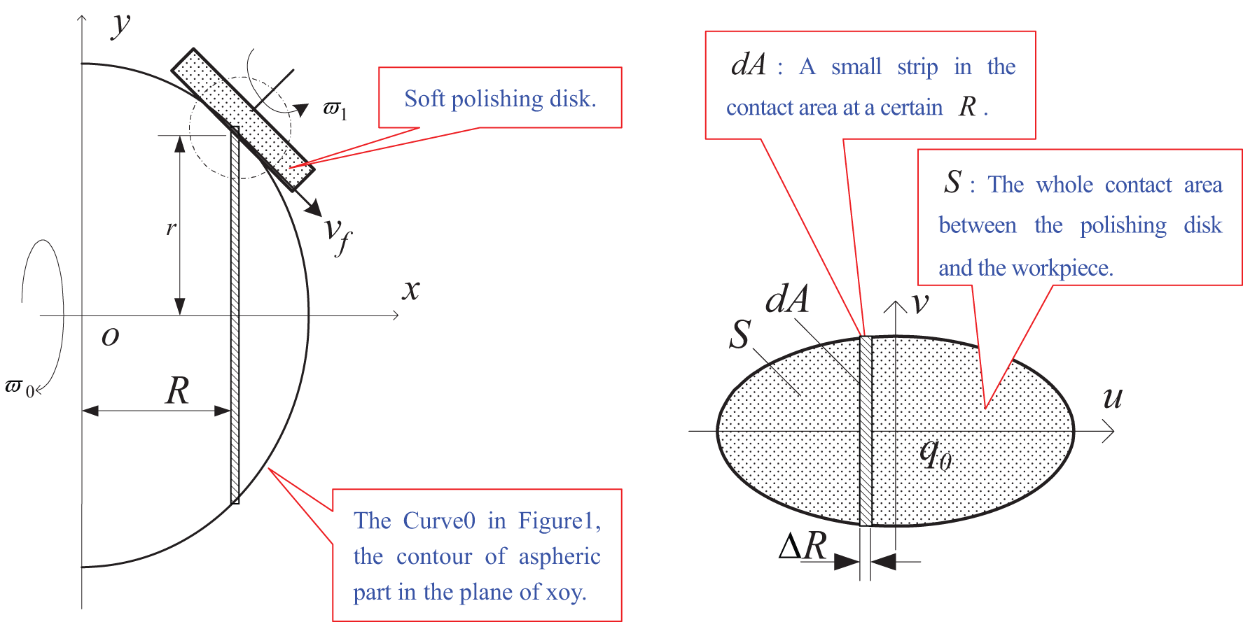
Contact area in the aspheric surface polishing with a lathe: (a) model of contact condition and (b) enlarged contact area.
When the polishing tool is a ballonet wheel, the value of the contact stress is almost the same as everywhere in the whole contact area. Define

The rotational speed of the spindle of a lathe is always too high to be changed abruptly online. As a matter of fact, it is usually set as a constant. So
In a real system,


Computed depth of material removal with different
Analysis and discussion
According to Figure 4, in the usual cases of
When
When
When
For the sake of chip removal,
Polishing experiments
On an ordinary CNC lathe of two-axis interpolation theory, this article has developed a compliant polishing system for aspheric surface precision machining under the hybrid motion or force control policy,16–19 in which a torque-servo device is used to control the normal force, as shown in Figure 5. The system includes three subsystems.17,18 The first one is the machining movement controlling subsystem, which is composed of 1 and 2. The machining movement is driven by the rotational motion of the spindle of the CNC lathe. The second one is the feed movement controlling subsystem, made up of 4 and 5. The polishing tool holder could rotate around 9, while 5 provides the feed movement in two orthogonal directions. By moving 5 and turning 4, we could keep the normal force just in the normal direction. The third one is the normal force controlling subsystem, composed of 6, 7, 8, and 9. A stepper motor, the device 6, transmits the required rotational displacement on 7, and the output torque of 7 would then be transmitted to 9 through 8. A torque sensor installed on 7 would detect the output torque. When the output torque changes from its required value, the input current would be adjusted to drive the stepper motor change its output displacement automatically to make the normal force at its expected value.
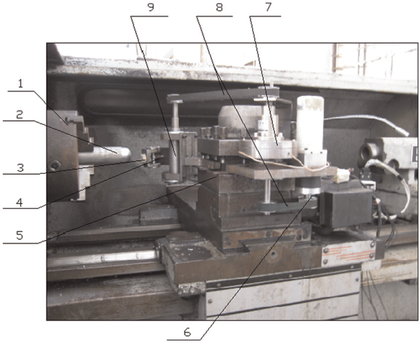
Aspheric surface polishing system.
Polishing experiments are performed as shown in Table 1 with the parameters shown in Table 2. The surface roughness is scanned and shown in Table 3, and the photograph of the aspheric workpiece is shown in Figure 6. After being polished 22 times, the surface roughness of the aspheric surface of equation (17) has been changed from
Polishing procedures.

Parameters of experiments.

Surface roughness measured.

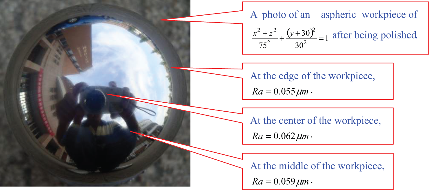
Photograph of an aspheric workpiece after being polished.
Conclusion
In the process of aspheric workpiece polishing, the polishing tool is usually made rotating to remove cutting scraps and broken abrasives from the contact area. Even if the rotational speed of the spindle of a CNC lathe provides the machining movement for aspheric surfaces polishing, the rotational speed of the polishing tool would increase the efficiency in material removing. The higher the speed of the polishing tool, the greater the material removal. But higher rotational speed of the polishing tool would result in nonuniform material removal. In general, the rotational speed of the polishing tool is small, and it does not have great influence on the volume of material removed from the workpiece, but it could have significant influence on surface roughness.
In detail, the rotational speed of the polishing tool has almost the same influence on the volume of material removed whether it rotates in the same direction or in the reserve. But when
Footnotes
Appendix 1
Acknowledgements
The authors extend our thanks to all the graduate students in our team for their great jobs: Jianbo Zhang, Bida Lv, Sihai Yu, Mingqin Zhang, and Xiangen Ying.
Academic Editor: Ramiro Martins
Declaration of conflicting interests
The authors declare that there is no conflict of interest.
Funding
All the research works are supported by the Natural Science Foundation of Zhejiang Province of China under granted nos LY12E05007 and LY12E05014, the Industrial Major (Key)-Commissioned Research of Ningbo City of China under granted no. 2012B10057, and K.C. Wong Magna Fund in Ningbo University.