
Abstract
This article studies the precision motion control of a long-stroke reticle stage driven by the permanent magnet linear motor in wafer scanner. A robust sliding-mode control method is proposed for tracking the reference trajectory in the presence of un-modeled dynamics, parametric uncertainty and external disturbances including force ripple, cogging and friction in the controlled system. A modified sliding-mode term based on the variable structure technique for eliminating the tracking error is employed in the proposed control law. The system stability and tracking convergence of the closed-loop control system are guaranteed by Lyapunov theory theoretically. The feasibility and effectiveness of the proposed method are demonstrated by comparative experiments on a linear motion testbed. The experimental results show that better tracking performance can be achieved by the proposed method compared with the conventional proportional–integral–derivative method and it can be considered as a possible alternative in the precision motion control system.
Introduction
Wafer scanner is highly complex equipment used in the semiconductor industry for the production of integrated circuits (ICs). Wafer stage and reticle stage are the key sub-systems in the wafer scanner, containing the patterns of IC and the silicon wafer to be exposed, respectively. 1 In the semiconductor manufacturing, a laser beam passes the desired image mask held by the reticle stage, through an optical lens system which can scales down the image, onto the surface of the wafer covered by a layer of light-sensitive material. Then the patterns are transferred from the mask to the wafer and an exposure is achieved. 2 During scanning, only a small area on the wafer is exposed and then the stage will be stepped to the next area to finish the next cycle. The quality of wafer scanner including accuracy and throughput is mainly determined by the tracking performance of the two stages. Only several nanometers of position tracking error are allowable during the scanning. This makes the control of wafer scanner challenging.
Currently, to achieve nanometer-scale tracking and positioning, dual-stroke strategy is employed in the wafer scanner, with long strokes for coarse positioning and short strokes for high-speed precise positioning. 2 For the reason of presentation, the discussion is mainly limited to the long-stroke reticle stage in this article. Permanent magnet linear motor (PMLM) is widely used in the field of ultra-precision motion control. For wafer scanner, PMLM is usually adopted as the long-stroke actuator. In addition to the un-modeled dynamics and parametric uncertainty, many external disturbances may degrade the performance of the closed-loop control system such as force ripple, cogging, friction, and vibration. 3 This makes the control system of wafer scanner more complex.
Some drawbacks limit the applications of conventional proportional–integral–derivative (PID) methods in the precision motion control field: (1) they work best with systems that have only one input and output; (2) the plant to be controlled might not behave in a linear fashion; and (3) the changing of the plant dynamics due to changes on the loads, wear, and tear, and mechanical effectiveness in mechanical elements may degrade the performance of PID control systems. Therefore, more advanced control methods are essential.
In Heertjes and Van de Molengraft, 4 Heertjes and Tso, 5 Mishra and Tomizuka, 6 and Mishra et al., 7 iterative learning controllers (ILCs) are proposed for wafer scanner. These studies show that no plant information is required for ILC and a good performance can be achieved in the presence of repetitive disturbances. However, ILC may result in a degraded performance under the effect of non-repetitive disturbances such as cable forces and structure vibrations. 3 Some researches focus on disturbance observer-based (DOB) method which can compensate for the impacts of the uncertainties and external disturbances.8–13 DOB is used to compensate for the uncertainties of parameter variations and current measurements, in the velocity and current loops, respectively. 10 A composite method based on DOB is proposed in Li et al. 11 The modeling error of the nonlinear effects is regarded as lumped disturbances which can be estimated by DOB. However, the results presented in Yao and Xu12,13 show that the wide range of discontinuous disturbances and parametric uncertainties cannot be handled well by DOB.
Recently, sliding-mode control approach based on variable structure technique develops rapidly and has been widely applied in the field of precision motion control.14–17 A sliding-mode control and a PI-based equivalent disturbance observer are proposed for the control system of a tubular synchronous linear motor. 16 The distinctive peculiarity of the proposed scheme is the use of a control law that guarantees the stability of the system regardless of the payload mass. An enhanced sliding-mode tracking control methodology is proposed for piezoelectric actuators to track desired motion trajectories. The convergence of the position tracking error to 0 can be ensured by the proposed methodology in the presence of the hysteresis effect and un-modeled disturbances. 17
In this article, a robust sliding-mode (RSM) control method is proposed for the control system of wafer scanner. This method is used to accommodate the parametric uncertainties, un-modeled dynamics, as well as external disturbances. The proposed method is formulated without prior information of the plant, and the stability of the closed-loop control system is guaranteed by Lyapunov theory.18,19 The contributions are briefly described as follows: (1) an RSM control method is proposed for the wafer scanner, (2) a modified RSM control law based on boundary layer technique is proposed for reducing the chatting effect, and (3) the feasibility and effectiveness of the proposed method are demonstrated by comparative experiments.
This article is organized as follows. In section “Dynamic modeling,” a mathematical model of PMLM for the long-stroke reticle stage is presented. In section “RSM control method for wafer scanner,” a modified robust sliding-mode (MRSM) control method is established and the stability analysis is conducted. The experimental study is detailed in section “Experimental study.” The experimental results are presented and discussed in section “Results and discussion.” Finally, some conclusions are drawn.
Dynamic modeling
The long-stroke reticle stage is driven by a current-controlled three-phase PMLM. Since the bandwidth of the current controller loop is large enough, its effect on the dynamics of outer loop will be neglected. The electro-mechanics model of the long-stroke reticle stage is given by

where
Dividing both sides of equation (1) by

where
Without loss of generality, assume that

RSM control method for wafer scanner
For mathematical model (2), an RSM control method is proposed to track the reference position
The position tracking error

Define special positive-definite function
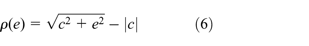

where
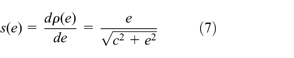
The time derivatives of

According to equations (5) and (9), we have

Substituting equation (10) into equation (2), the model becomes

Design the RSM control law
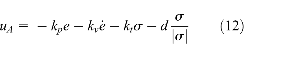
where
Substituting control law (12) into equation (11), the model becomes

Multiplying both sides of equation (13) by
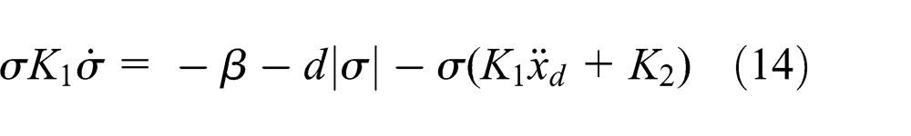
where

Replacing
and

where
Theorem 1
For electro-mechanics model (2), the RSM control law (12) assures the tracking convergence of the closed-loop control system with

Proof
It is to be noted that for plant (2), with the proposed control law (12), the functions
Choose a Lyapunov function

Differentiating
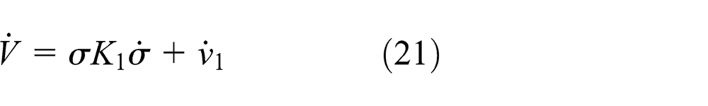
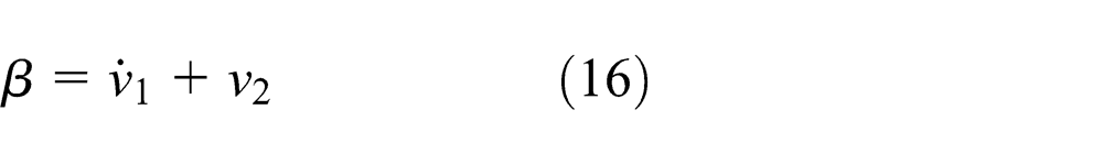
Substituting equation (14) into equation (21), we have

Substitution from equation (16),
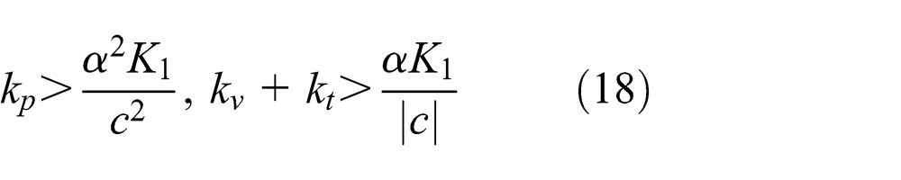
Applying the bounds given by equations (3) and (4), we have

With condition (19), the time derivative
It means

where
Replacing

Theorem 2
For electro-mechanics model (2), the MRSM control law (27) can assure the system stability and tracking convergence with
Proof
Similarly, choose the Lyapunov function
When
When
If

there exists a small positive constant

Structure of the MRSM control method.
Experimental study
To verify the effectiveness of the proposed method, a precision linear motion testbed is set up, as shown partially in Figure 2. The testbed consists of an industrial personal computer (IPC) with encoder acquisition card, a PMLM together with inbuilt optical encoder sensor, a servo amplifier, and a digital-to-analog (D/A) control card. The block diagram of the architecture of the testbed is shown in Figure 3. The PMLM model BLMC-92 is manufactured by AEROTECH and the force constant
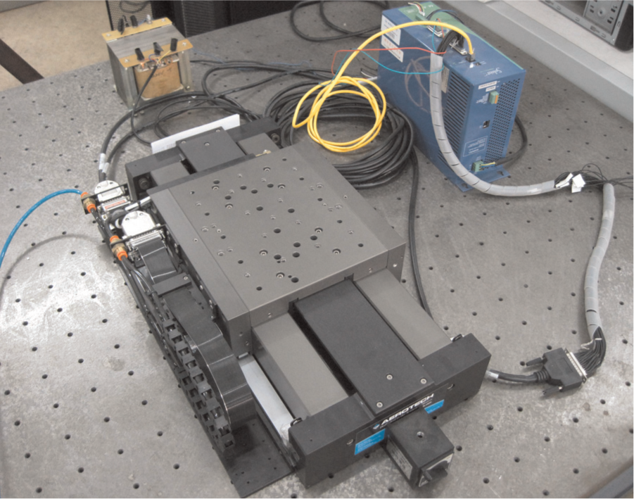
Experimental study facility.

The architecture of the testbed.
Standard identification processes based on frequency response of the open-loop system are carried out and the measured transfer function from the control input

Measured frequency response function in Bode representation.
In the experiments, the reference motion trajectory is chosen as a class of third-order set-points, as shown in Figure 5. The trajectory consists of three phases: (1) accelerating to the specified scanning velocity, (2) scanning at this velocity, and (3) decelerating to stationary state.
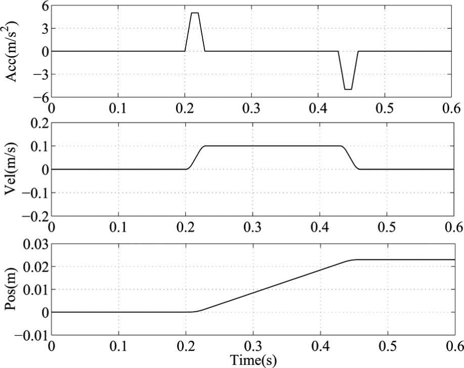
Reference motion trajectory.
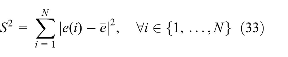
To evaluate the performance of the control system for the wafer scanner, the methods will be compared based on the following indexes:
Moving average (Ma) and moving standard deviation (Msd) are the measures for the low-frequency and high-frequency parts of the positioning errors with 25
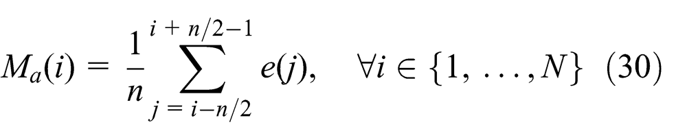

where
Settling times
Peak position error


where
In this article, to further evaluate the effectiveness of the proposed method in the physical system, three control methods are compared in the experiments.
PID
Conventional PID controller with low-pass filter is given by

where
RSM
RSM control method is described in equation (12). By trial and error,
MRSM
MRSM control method is presented in equation (27). Same parameter values are chosen as aforementioned RSM.
Results and discussion
In the experiments, the closed-loop system is required to follow the reference trajectory shown in Figure 5. To be noted, the testbed working in an open environment is easily influenced by the external disturbances such as vibration, air flow, and temperature. Therefore, the experimental results may be affected, to some extent. Three experiments based on the three methods PID, RSM, and MRSM involved in section “Experimental study” are carried out.
Despite the open environment problem, the results show that the proposed method achieves a promising tracking performance. The resulting position tracking errors in experiments are compared in Figure 6. And the tracking accuracy indexes
Tracking accuracy indexes.

PID: proportional–integral–derivative; RSM: robust sliding-mode; MRSM: modified robust sliding-mode.

Position tracking errors in the experiments.
From the experimental results, it can be seen that the convergence speeds of the two methods based on RSM technique are obviously faster than the PID method in the settling phase. The position tracking error for the modified method is much smoother than the RSM method and the boundary layer technique has a significant effect on reducing the chatting effect of the sliding-mode. The proposed MRSM has a better performance than the other two methods on the tracking accuracy indexes
Figure 7 compares the estimated velocity errors in three experiments. We can see that there is a significant velocity tracking error during the non-steady phases for PID method and the peak error is up to 8.8 mm/s. By comparison, the performance of velocity tracking is much better for the proposed MRSM method and the peak velocity tracking error is only 4.9 mm/s. Because of the chatting effect, during the steady state, violent velocity fluctuations can be observed for RSM method and the range is about ±2 mm/s.
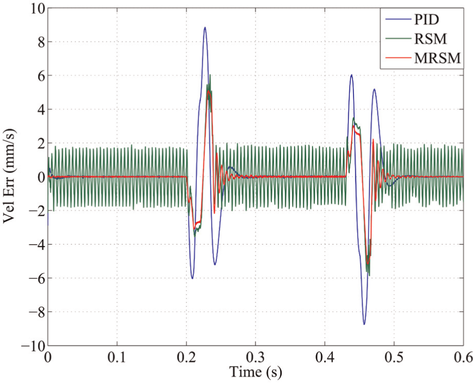
Estimated velocity tracking errors in the experiments.
Choose the exposure time as 70 ms, the resulting Ma and Msd position errors of the first acceleration and constant velocity scanning phases are compared in Figure 8. Accordingly, the settling times

Resulting Ma and Msd position errors.
Settling time specification.
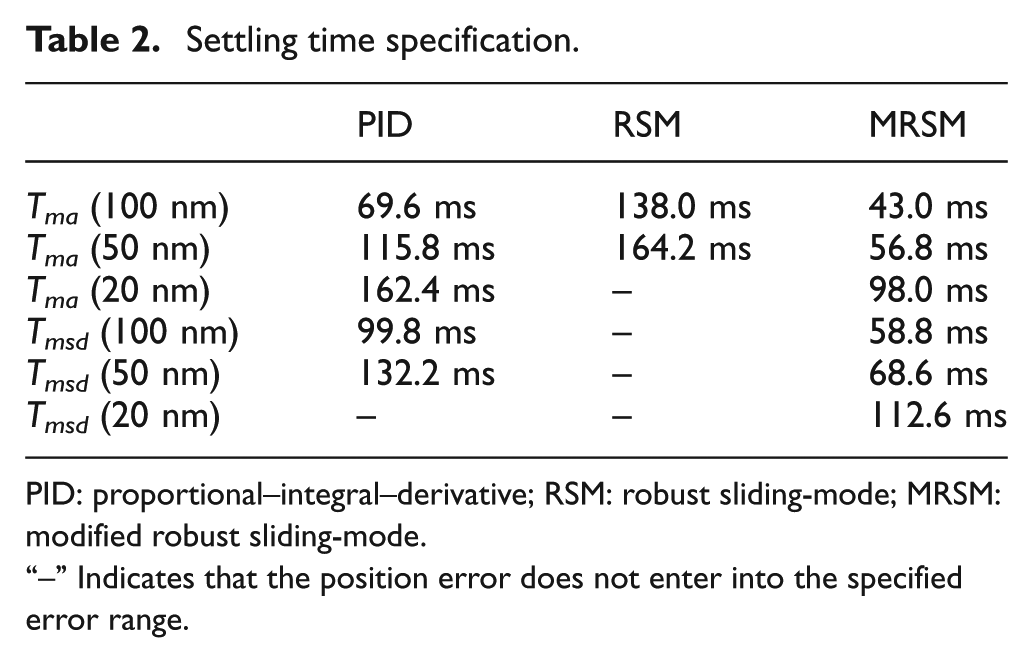
PID: proportional–integral–derivative; RSM: robust sliding-mode; MRSM: modified robust sliding-mode.
“–” Indicates that the position error does not enter into the specified error range.
The control inputs in the experiments are shown in Figure 9. In accordance with the analysis above, there are significant fluctuations of about 0.7 V during the steady state for the control input of RSM method. And because of the less precise velocity tracking, the peak control input for PID method is larger than the other two methods. By comparison, the proposed method can achieve better tracking performance with less and smoother control input signals.
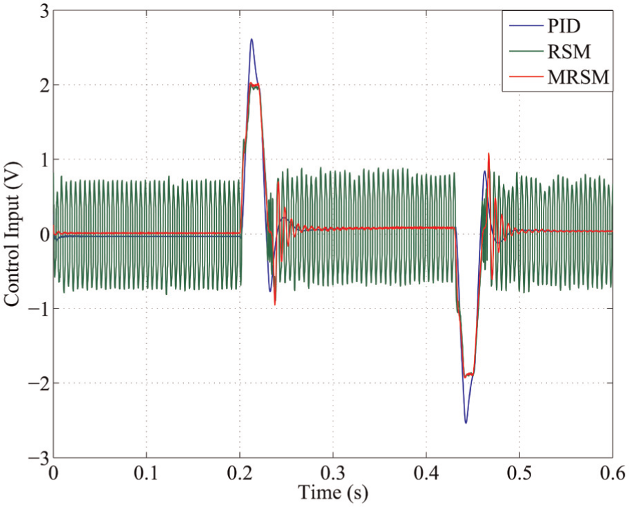
Control inputs in the experiments.
In summary, the proposed MRSM control method is demonstrated to be stable and effective. Compared with RSM and conventional PID methods, better tracking accuracy and settling time performance can be achieved. Especially, the chattering effect of sliding mode can be greatly reduced by the proposed method. Our future work will focus on establishing a 3-degree of freedom long-stroke wafer stage and designing a multiple-input-multiple-output (MIMO) controller for it.
Conclusion
In this article, an MRSM control method is proposed to improve the tracking performance of the long-stroke reticle stage for wafer scanner. The feasibility and effectiveness of the proposed method are verified by comparative experiments on a linear motion testbed. The experimental results show that better tracking performance can be achieved by the proposed method in an open environment and it can be considered as a possible alternative to the conventional PID control method for wafer scanner.
Footnotes
Acknowledgements
The authors thank the editor(s) and reviewer(s) for their work and helpful suggestions for this article.
Academic Editor: Hamid Reza Shaker
Declaration of conflicting interests
The authors declare that there is no conflict of interest.
Funding
This research was supported by the National Science and Technology Major Project of the Ministry of Science and Technology of China (Grant No. 2009ZX02207) and by the National Basic Research Program of China (Grant No. 973-10007.07-LB7).