
Abstract
A coupled dynamic model, which contains helical gears-shafts-bearings for a wind turbine gearbox transmission system, was built considering nonlinear factors of the time-varying mesh stiffness, the external varying load, and the dynamic transmission error at first. The model is confirmed to be right after comparing the theoretical data with the experimental load sharing values, and also it is found that the static load sharing is conservative to evaluate the non-equilibrium effect of a planetary gear system. Besides, the analyzing results of the influence of average error and amplitude error on the load sharing show that the load sharing could be decreased if the error goes up a little. Then, by means of treating the static tracing point as the dynamic initial values, we analyzed the initial position’s influence on the load sharing of transmission system to provide a theoretical basis of load sharing control. Furthermore, we explored the influence of high-speed shaft position angle on the load sharing and the dynamic load factor of gears fixed on the parallel shafts. The results provide useful theoretical guidelines for the design of parallel shaft gear system in the wind turbines.
Keywords
Introduction
Wind turbine gearbox (WTG) transmission systems, whose performance affects the whole function and life of wind power system directly, are mostly composed of planetary gear stages and parallel gear stages. In the WTG, several planet gears are applied to achieve the power split in the planetary gear stage and then increase the load-carrying capacity of the WTG. However, vibration, shock, and noise will occur in the system if the load distribution of each planetary gear is not balanced. More severely, the gearbox will fail to work if the load is mostly concentrated on one planetary gear. Therefore, it is very important to analyze the load sharing characteristics of the WTG to ensure its operating efficiency and reliability. And also, the analyzing results can provide a theoretical guideline for the design of the gear system in a wind turbine.
Many researches focused on the load sharing dynamics of the planetary transmission system. Hidaka et al. 1 are the pioneers in studying the dynamic characteristics of planetary transmission system. They established a large-scale experiment device and found the phenomenon that the load distribution between teeth is uneven. Kahraman and colleagues2–4 established the static and dynamic model of a planetary transmission system by adopting the lumped mass method. He promoted static load sharing and dynamic load sharing to evaluate the equilibrium effect of the planetary system. And also he analyzed the influence of some components’ manufacturing error and assembly error on the load sharing. Then, Singh et al.5,6 and Ligata et al. 7 found that the position error of planet was the key factor which affected load sharing through the theoretical and experimental analysis. And Singh8,9 promoted the mechanism of load sharing based on the influence of the planet tangential error. Gu and Velex 10 and Gill-Jeong and Parker 11 established a nonlinear dynamic model of a planetary system, and the effect of eccentric error on the load sharing had been analyzed. Iglesias et al. 12 investigated the effect of planet position error on the load sharing through a finite element (FE) model. The model results presented a high degree of consistency with the expected load sharing ratios and transmission error qualitative values and proved its potential to simulate the behavior of a planetary transmission under a wide range of parameters. Chaari et al. 13 compared the cases of a healthy planetary gear and one with the presence of eccentricity and profile error, and it is found that the presence of eccentricity or profile errors significantly alters the dynamic behavior. Tang et al. 14 investigated the function relation between the system errors and the planet gear load and analyzed the influence of planet position errors on the load sharing. These authors have done a lot of research on errors, but they did not discuss the effect of average error and amplitude error on load sharing.
Recently, many authors paid attention to the load sharing of a gearbox composing of both the planetary system and the parallel gear sets. An original hybrid FE/lumped parameter model of planetary/epicyclic gear sets had been set up by Abousleiman and Velex. 15 It has been found that ring-gear flexibility modifies static load distributions and critical tooth speeds on internal meshes. Based on the mesh stiffness model of the internal gear pair with tooth root crack, Chen and Shao 16 studied the influence of the crack on the dynamic responses of the planetary gear set, and the trajectories of sun gear center were compared under different crack degrees. Zhou 17 , Sun et al., 18 Bao and Zhu, 19 and Zhang 20 also studied the trajectory of sun gear center under static and dynamic situations. However, there are few people deeply studying how the load sharing varies when the initiative position of sun gear center changes in a WTG. Our research will complement the literature.
In general, the planetary and parallel shaft transmissions are integrated in a WTG. As a result, the multi-body modeling techniques can be used to model this system. Given the increasing degree of complexity, Helsen et al. 21 classified the multi-body models into three types of models, namely, purely torsional models, 6-degree-of-freedom (DOF) rigid multi-body models with discrete flexibility, and full flexible multi-body models. And full flexible multi-body models were shown to be the most accurate after comparing the simulation results with the experimental data. In addition, plane modes, helical modes, and global modes were classified in full flexible multi-body models. Parker and his colleagues22–24 compared a lumped parameter model and a FE model from the aspect of modal vibration. He found that the results of the lumped parameter model and the FE model are of no difference in the planetary system with three planet gears. Qin et al. 25 formulated a flexible multi-body dynamic model of a horizontal WTG composed of a planetary and a conventional parallel axis gear sets to study the system dynamic behavior within an integrated whole system. And they predicted the result of the dynamic transmission error to understand the overall dynamic behavior of the drive train system. Wei et al. 26 proposed a coupled model of the two planetary stages and a parallel stage of a WTG. With this model, they analyzed the effects of application factor and the dynamic load factor, and found that the dynamic load factor of parallel shaft is the biggest. Draca 27 established a FE model of two parallel-stage axis gear sets and analyzed the influence of position angle on transmission error. However, few people pay attention to the influence of high-speed shaft (HSS) gear position angle on the load sharing and the gear dynamic load factor within an integrated whole WTG system. HSS is an important part of transmission system, and the output performance of the system is determined by its dynamic characteristics. The research results of this article will fill in this gap.
The main purpose of this article is to analyze the dynamic load sharing characteristics of the WTG transmission system. A coupled dynamic model, which contains helical gears–shafts–bearings for the WTG, is built considering nonlinear factors of time-varying mesh stiffness, external varying load, and dynamic transmission error together. This model is confirmed to be right after comparing the theoretical data with the experimental load sharing values. Then, the effects of error excitation, sun gear center’s initial position, and HSS gear position angle on the load sharing are analyzed. The dynamic characteristic of WTG is further understood by comparing the load sharing coefficient with the gear dynamic load factor. The result provides useful theoretical guideline for the design of parallel shaft gear system and adjusting load sharing in the WTG.
Modeling the wind turbine transmission system
The structure of WTG
A typical 1.5 MW WTG is composed of a planetary stage and a helical stage, as is shown in Figure 1. The planetary gear system includes three planet gears, a planet carrier, and a floating sun gear, which are represented by planet gears, carrier, and sun, respectively, in Figure 1. The parallel helical stage is composed of four helical gears, among which Helical 1 (H1) is the helical gear on low-speed shaft (LSS), Helical 2 (H2) and Helical 3 (H3) are the helical gears on middle-speed shaft (MSS), Helical 4 (H4) is the helical gear on HSS. In the parallel stage, bn
(n = 1, …, 4) represents the equivalent bearings supporting the corresponding gears. The transmitting process of load in this WTG is as follows: the input load is transmitted to the planetary carrier through the hub and spindle, the sun gear rotates and drive the sun gear to rotate, and the output load is from the HSS in the WTG transmission system. Figure 2 illustrates the side view of the transmission system, and the position angle of HSS
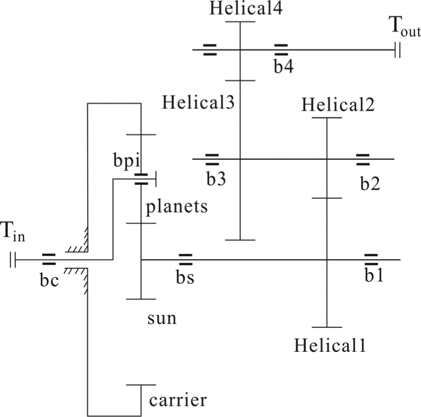
Schematic of the WTG transmission system.

Side view of the transmission system.
Static model
Figure 3 shows the static model of the planetary system proposed by Kahraman.
4


The static model of the planetary system.
The displacement of center of the sun gear in x direction is denoted by xs , and the one in y direction is denoted by ys . Then, the floating of the sun gear is

In equation (3),


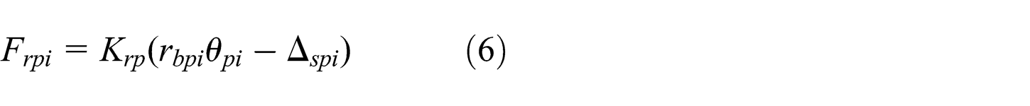
In equations (5) and (6),
Then, the static equilibrium equations of the planetary transmission system are

In equation (7), Ta is the torque that acts on the sun gear.
According to the static equilibrium equation (7), the load sharing of the planetary system can be obtained with equation (8)

Dynamic model
Equivalent dynamics model and equilibrium equations
The three-dimensional equivalent lumped mass model of WTG transmission system is shown in Figure 4. As it is shown in Figure 4, the system

The coupled dynamic system of WTG transmission system.
In Figure 4,
We need to decompose the displacements along the meshing line when we calculate the dynamic meshing force of gear pair. It can be obtained from the relative displacement analysis of spur gear meshing model which is brought forward by Parker and colleagues.28,29 The relative displacement along the meshing line between sun gear and planet gear is

In equation (9),
However, since all the gears are helical gears in our model, the relative displacement of sun–planet in helical model is revised as

In equation (10),
Accordingly, the relative displacements along the meshing line of other components are

In equation (11),
The equations of motion for the carrier, the sun gear, the planet gears, and the helical gears (H1, H2, H3, and H4) are formulated as follows.
The equation of motion for the carrier is

The equation of motion for the sun gear is
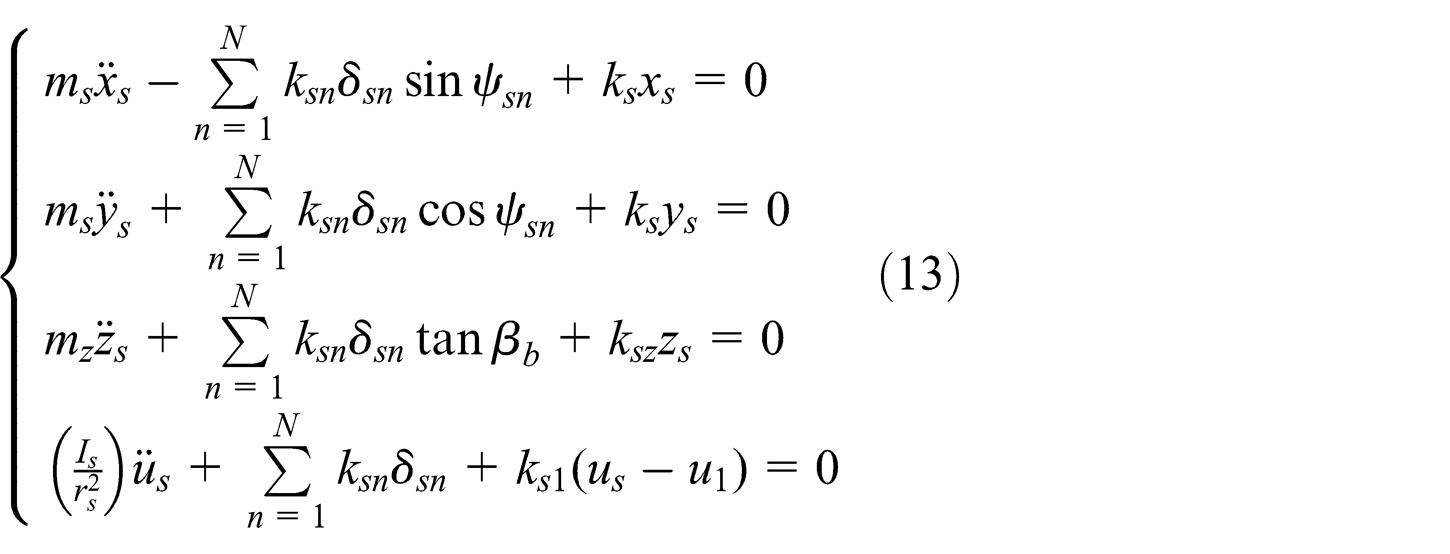
The equation of motion for the planet gear is
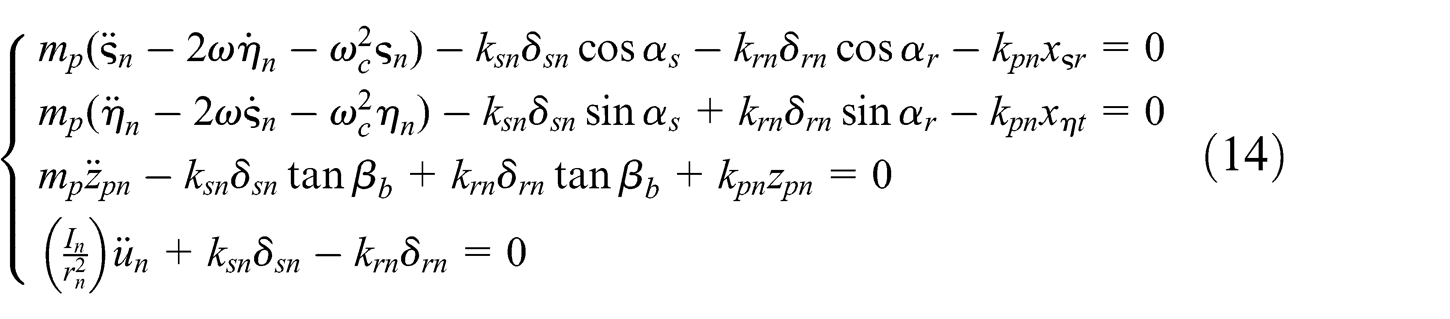
Helical gear, H1, is coupled with sun gear, and the equation of motion is

Helical gears, H2 and H3, are assembled on the same shaft, and the equation of motion is

The equation of motion for the helical gear, H3, is

The equation of motion for the helical gear, H4 is

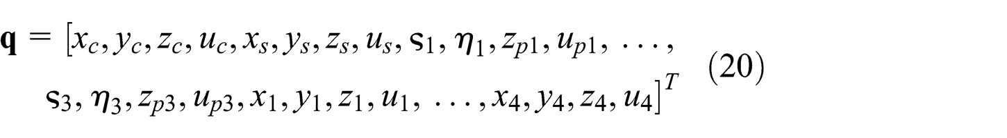
All the equations from equations (12) to (18) constitute the differential equations of motion for the WTG transmission system, and we can shift the equations into a matrix form, which is represented in equation (19)

There are 36 DOFs in these matrixes. In equation (19),
Excitation analysis
Time-varying mesh stiffness excitation.
Time-varying mesh stiffness excitation30–34 is a dynamic excitation to the gear system caused by the alternate appearance of single tooth and multiple teeth in the mesh procedure. It results in the periodical change of mesh stiffness and gear load. In order to obtain precision results, we adopt a 7-term Fourier expansion to depict the time-varying mesh stiffness excitation,

In equation (21),
External excitation.
External excitation at the input terminal, Tin , is caused by the wind varying speed, and it is composed of the mean component, Tin_m , and the varying component, ΔTin , and it is computed by
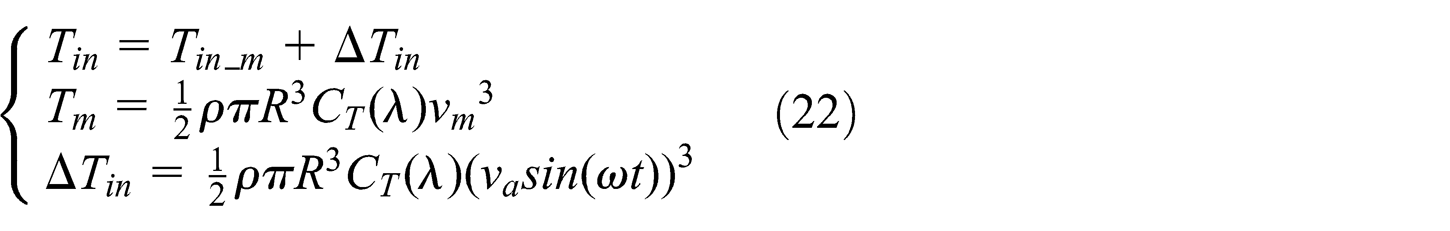
where
The external excitation at the output terminal is defined by
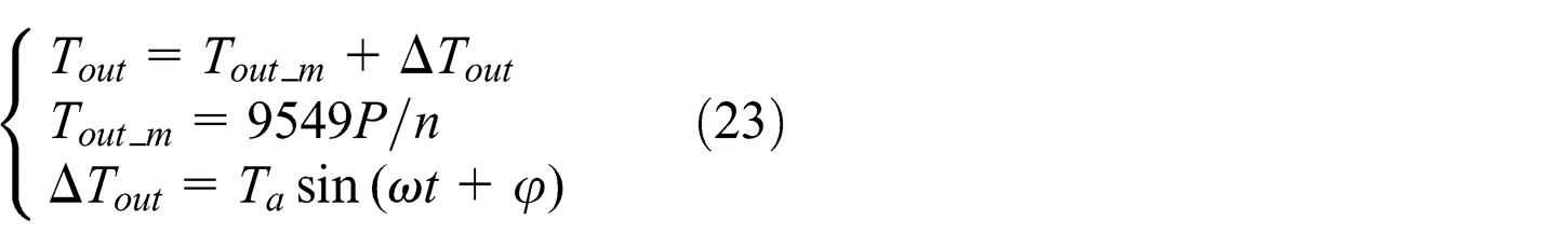
where P is the rated power;
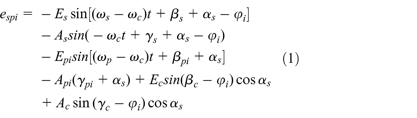
Error excitation.
We consider the error excitation in a simple way; as a result, the expression of error excitation in the form of trigonometric function is

where
Dynamic load sharing and gear dynamic load factor
In the equilibrium equations from (12) to (18), we suppose that the dynamic force between the planet gear and the sun gear is

We adopt a numerical method to solve these equations. First, we have to calculate the load sharing in every cycle of the teeth frequency with equation (26)

In equation (26), n = 1, 2, …, N, N is the number of the planet gears, j = 1, 2, …, n 1, k = 1, 2, …, n 2, and n 1 and n 2 are the cycle numbers of teeth frequency in external mesh and inner mesh, respectively.
Then, we can define the load sharing in the whole cycle as

In equation (27),
The gear dynamic load factor,

In equation (28),
However, load sharing is a parameter to weigh the ability to split load equally from the main shaft. The gear dynamic load factor is also used to evaluate the dynamic performance of gears. From the concept of sharing load, load sharing and gear dynamic load factor are the same, and their difference comes from the objects they describe. If we use the dynamic load factor to express load sharing, it will be

Results and discussion
Computational load sharing and experimental load sharing
To illustrate the models and the methods proposed in the above sections, herein, we apply them to investigate the loading sharing characteristics of a specific 1.5 MW WTG. The parameters of this WTG are as follows. Rated power, P, is 1.5 MW, the number of the planet gears is 3, the input rotating speed of planet carrier,
Parameters of the WTG transmission system.

With the data listed in Table 1, the static loading sharing, shown in Figure 5, is obtained from the static equilibrium equations. As it is shown in Figure 5, the static load sharing of the 1.5 WM WTG transmission system is 1.1875.

Static load sharing.
Figure 6 shows the dynamic load sharing of external meshing, and its average value is 1.0903, while the internal dynamic load sharing is shown in Figure 7, the value is 1.0925. Therefore, dynamic load sharing of the transmission system is 1.0925.
Dynamic load sharing of external meshing.

Dynamic load sharing of internal meshing.
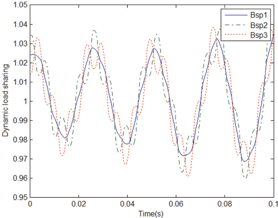
Experimental load sharing is obtained under different torques, and the results 35 are shown in Table 2. We can see that the load sharing of the studied WTG transmission system is in the range of 1.02–1.08. For the torques, 880 kN m is the rated input torque, and the load sharing is 1.08 under this torque.
Experimental load sharing under different input torques.

Comparing the dynamic simulation result with the experimental load sharing obtained under the rated inputting torque, we can find that the error is 1.897%. This result shows that the dynamic simulation and the experimental result are in good fitting, which indicates the validity of the proposed models and methods. However, the error of static load sharing and experimental load sharing is 9.95%. The error difference shows that the dynamic load sharing is closer to the actual experimental values, while static, the load sharing is more conservative to evaluate the system. In order to get the most uneven situation of the synthetic meshing errors, we define the phase angles of the planet gear errors to be the value when their positions are parallel to the meshing lines, 33 and then the solving results of static equations become bigger than the ones they should be. To deeply understand the load sharing capacity of the 1.5 MW WTG, we will investigate how the error excitation, the position of the sun gear center and the HSS position angle affect the dynamic load sharing in the following three subsections with the methods proposed in sections “Modeling the wind turbine transmission system” and “Dynamic load sharing and gear dynamic load factor.”
Effect of error excitation on the dynamic load sharing
The error excitation is one of the most important factors affecting the disequilibrium of planet load distribution. We will explore the effect of error excitation on the dynamic load sharing of the 1.5 MW WTG transmission system in this section. As it is displayed in equation (4), the error excitation is composed of the average error and the amplitude error. Therefore, we investigate their influence on the dynamic load sharing of the WTG separately.
First, we observe how dynamic load sharing varies with the change of average error if the value of amplitude error is kept constant. Herein, five different values of amplitude error, 0.2, 0.1, 0.05, 0.031, and 0.01, are chosen to investigate this phenomenon. The curve plotted in Figure 8 shows that the dynamic load sharing is linearly increased as the average error goes up. Besides, a bigger amplitude error makes a smaller dynamic load sharing, which is also shown in Figure 8(b).

The influence of average error on dynamic load sharing: (a) overall contrast figure and (b) local contrast figure.
Then, the effect of amplitude error on the dynamic load sharing under five different values of average error, 0.2, 0.1, 0.063, 0.01, and 0.005, is investigated. In Figure 9, we can see that the dynamic load sharing changes slightly at the range,

The influence of amplitude error on load sharing: (a) overall contrast figure and (b) local contrast figure.
The results shown in Figures 8 and 9 reveal that the dynamic load sharing is determined by both the average error and the amplitude error. The smaller the average error is, the more stable the system will be. And also, increasing the amplitude error could decrease the dynamic load sharing of the WTG at a certain degree, although the risk of harmful effect on the system will increase if the amplitude error exceeds this value. Therefore, when we manufacture and assemble the WTG, we should keep the average error and the amplitude error as smaller as possible.
Effect of sun gear’s initial position on the dynamic load sharing
In the planetary system, the planet gears rotate around the axis of sun gear besides their own rotations. The error azimuth angle of planet gear changes as its position varies. Therefore, the center position of sun gear also changes due to the variation in the position angle and the error azimuth angle of planet gear. Figure 10 illustrates the static trajectory of sun gear center in the WTG, and there is a hollow area in it. Figure 11 shows the static trajectory of sun gear center without considering the effect of ring’s manufacturing error and assembly error. Obviously, there is no hollow area in it. The difference shows that when WTG operates, the manufacturing error and the assembly error of the ring will cause the actual initial position of sun gear center to displace from its ideal rotating axis. This displacement will result in the variance of the load sharing capacity.

The static trajectory of sun gear center.

The trajectory of sun gear center without the ring error.
In order to analyze the effect of sun gear’s initial position on the dynamic load sharing, we define the position point of sun gear center (the coordinate value of sun gear center) as the initial value of solving the dynamic equations. Then, we can observe and record the dynamic load sharing under different position points of sun gear center. The initial coordinate values of the system are

Points of x series and y series within the range of sun gear center trajectory.
With the above-mentioned process, the load sharing of x series and y series is plotted in Figure 13. It can be found that the load sharing changes slightly, and its value fluctuates around 1.0925. We round it to be 1.09 in the following context. Meanwhile, the tangential coordinates and normal coordinates of planet gear (only the data of one planet gear are given here) on x = 0 series and y = 0.04 series are shown in Figure 14(a) and (b), respectively. As it is shown in Figure 14, both the tangential coordinates and the normal coordinates of planet gear increase or go down at the same time, and the change is linear.
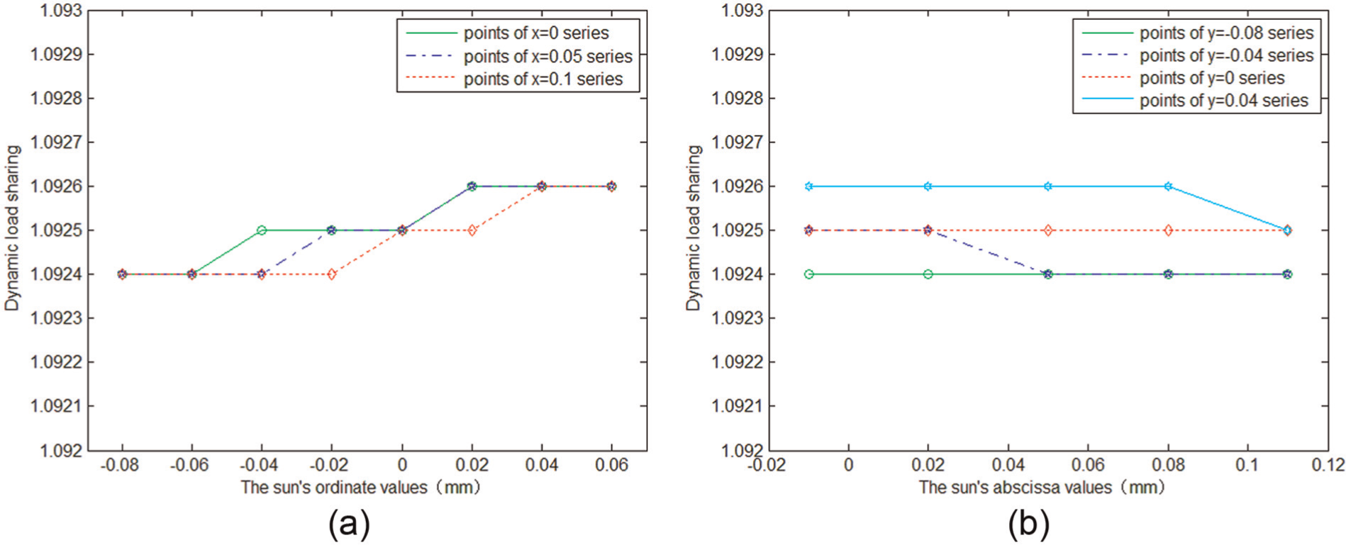
Load sharing under different initial values: (a) load sharing at different x series and (b) load sharing at different y series.

Contrast of the coordinates of plate gear center: (a) the contrast of planetary coordinates at x = 0 series and (b) the contrast of planetary coordinates at y = 0.04 series.
According to equations (27)–(29), the load sharing of the WTG transmission system,

where xr
= 0, yr
= 0, ur
= 0, upn
is almost 0, so we can neglect it, and

The increments of the tangential and normal coordinates of planet gear at given x series and y series are listed in Table 3. It can be seen that the order of magnitude of
Increments of tangential and normal coordinates of planet gear at given x series and y series.

The above analysis is based on a fact that the initial position of the sun gear center varies within the range of the trajectory of sun gear center. To obtain more convincing results, now we study how the load sharing reacts when the initial value of sun gear center is out of the range shown in Figure 12, taking x = 0 series, y = 0 series, and x = y series as examples. The longitudinal coordinate will expand to 100 mm under x = 0 series, the horizontal coordinate will expand to 100 mm under y = 0 series, and the longitudinal coordinate and the horizontal coordinate both will expand to 100 mm together under x = y series. The results in Figure 15 show that the load sharing rises when the absolute value of the coordinate increases, in other words, the further the center of sun gear is from the original point, the bigger the load sharing will be. Therefore, it can be concluded that the dynamic load sharing of WTG will keep stable if the misalignment of sun gear is limited within a proper range. These results are also feasible for other types of WTG.

Variation in load sharing with the increase in initial value beyond the range: (a) overall contrast figure and (b) local contrast figure.
Effect of HSS position angle on the dynamic load sharing
HSS is an important component of the WTG transmission system, and the output performance of this system is determined by its dynamic characteristics. In this subsection, we will compute the load sharing and the gear dynamic load factor and investigate the effect of HSS position angle on them.
According to equations (19) and (28), the gear dynamic load factors of MSS and HSS are shown in Figures 16 and 17, respectively. The results show that the two factors are both time-varying and their maximum values are different. Herein, the maximum values are defined as the final value of dynamic load factors; therefore, the dynamic load factor of MSS gear is 1.233, and the dynamic load factor of HSS gear is 1.393.
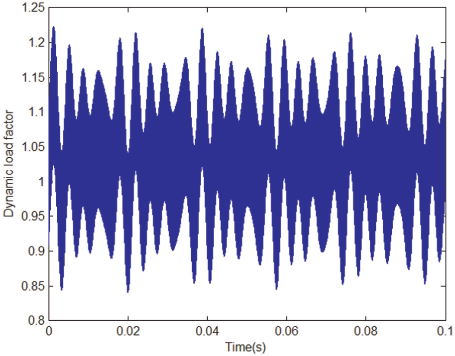
Dynamic load factor of MSS gear.

Dynamic load factor of HSS gear.
In order to study how the HSS position angle influences the load sharing and the gear dynamic load factor in the WTG system, we adopt the position angle from −20°, 0°, 20°, 40°, ..., to 340° with the increment of 20° per step. Then, the angles are substituted in the relative equations, and the computing results are illustrated by Figures 18 and 19.
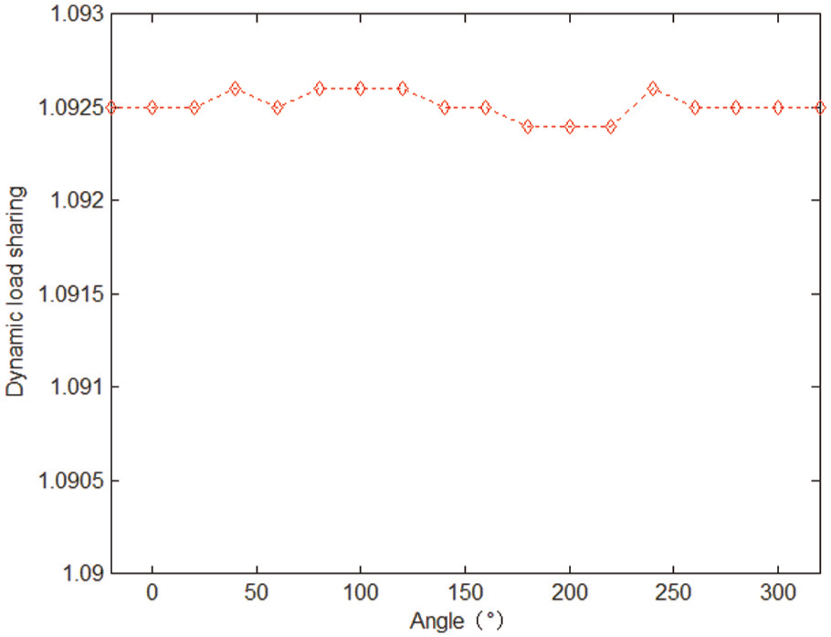
Load sharing when the position angle changes.

Dynamic load factor of HSS gear when the position angle changes.
As it is shown in Figure 18, the value of load sharing is almost kept at 1.0925 when the HSS position angle increases from 0° to 300°. We can conclude that load sharing is not influenced by HSS position angle. Among MSS gear dynamic load factor, HSS gear dynamic load factor, and load sharing of the WTG system, the value of HSS gear dynamic load factor is the biggest and load sharing is the smallest. It shows that the stability and life span of the WTG system can be improved if we can lower the dynamic load factor of HSS gear.
As it is shown in Figure 19, the dynamic load factor of HSS gear varies dramatically with the increase in HSS position angle. The dynamic load factor decreases slightly when the position angle changes from −20° to 60°, and then it increases until the position angle is 120°. After that, it decreases to a certain value and climbs smoothly when the angle varies from 140° to 240°. However, it changes dramatically at the range from 260° to 320°, and this sharp fluctuation means that the change of position angle of HSS gear will exert a big impact to the dynamic characteristics of the WTG transmission system.
The value of gear dynamic load factor is determined by

(a) The relative displacement of the HSS gear pair, H3–H4, at x direction and (b) the relative displacement of the HSS gear pair, H3–H4, at y direction.
The analyzing results from Figures 16–20 show that HSS position angle has a big influence on the gear dynamic load factor. If the position angle is chosen inappropriately, it will cause the instability and unexpected impact of the WTG and then result in the failure of gears in advance. To obtain lower HSS gear dynamic load factor, the HSS position angle should be chosen between −20° and 80° in this 1.5 MW WTG system. Generally speaking, when we design a WTG, we should choose the HSS position angle properly to ensure the stability and the life span of the gear transmission system composed of several gear stages in the wind turbine.
Conclusion
In this study, a dynamic model of WTG with planetary system is established to investigate the theoretical load sharing of WTG transmission system, and the analytical solutions are validated by the numerical and experimental load sharing results of a 1.5 MW WTG system. In addition, the effect of the error excitation, the sun gear center’s initial position, and the HSS position angle on the load sharing characteristics of WTG are analyzed. Based on the results presented in the above sections, the following conclusions can be drawn.
First, the static load sharing is a bit conservative to evaluate the planetary transmission system, while the dynamic load sharing is more effective to evaluate the dynamic performance of WTG.
Then, the load sharing is determined by both the average error and the amplitude error. The smaller the average error is, the more helpful the system will be. Besides, increasing the amplitude error could decrease the load sharing of the WTG to a certain extent.
Furthermore, the load sharing of the WTG system cannot be changed no matter how we change the initial distribution of the planet gears, which means that this parameter is determined by the construction of WTG. Therefore, we can cut down the value of this parameter within the zone of reasonableness by adjusting the floating structure and controlling the component errors in the WTG, such as shaving the gear teeth or improving the gear stiffness.
Finally, the load sharing is not influenced by the HSS position angle, while the HSS gear dynamic load factor is greatly influenced by this parameter. If the HSS position angle is chosen properly, it will effectively decrease the HSS gear dynamic load factor, and then the stability and life span of the WTG system can be improved and vice versa.
Footnotes
Acknowledgements
The appreciations are given to Jiangsu Shinri David-Brown Gear System Co. Ltd, China, for providing experiment conditions.
Academic Editor: Hyung Hee Cho
Declaration of conflicting interests
The authors declare that there is no conflict of interest with respect to the publication of this article.
Funding
This study is supported by National Science Foundation of China under grant no. 50803022.