
Abstract
This article proposes a novel method for identifying the motion errors (mainly straightness error and angular error) of a linear slide, which is based on the laser interferometry technique integrated with the shifting method. First, the straightness error of a linear slide incorporated with angular error (pitch error in the vertical direction and yaw error in the horizontal direction) is schematically explained. Then, a laser interferometry–based system is constructed to measure the motion errors of a linear slide, and an algorithm of error separation technique for extracting the straightness error, angular error, and tilt angle error caused by the motion of the reflector is developed. In the proposed method, the reflector is mounted on the slide moving along the guideway. The light-phase variation of two interfering laser beams can identify the lateral translation error of the slide. The differential outputs sampled with shifting initial point at the same datum line are applied to evaluate the angular error of the slide. Furthermore, the yaw error of the slide is measured by a laser interferometer in laboratory environment and compared with the evaluated values. Experimental results demonstrate that the proposed method possesses the advantages of reducing the effects caused by the assembly error and the tilt angle errors caused by movement of the reflector, adapting to long- or short-range measurement, and operating the measurement experiment conveniently and easily.
Introduction
Fast tool servo (FTS)–assisted diamond turning has been extensively used for compensating the motion errors of diamond turning machines 1 and producing freeform optical surfaces. 2 The schematic diagram of the FTS-assisted diamond turning is shown in Figure 1. Workpiece is clamped on the spindle, FTS is fixed on the slide of the machine which can move along the x-axis direction, and FTS can translate the cutting tool in and out of the workpiece as required.3,4 The accuracy of the machining system is basically determined by the motion accuracies of the spindle, the FTS device, and the slides. Since the slide is a linear motion component that can travel in a given trajectory and it is one of the important moving parts which can determine the surface roughness, the surface shape, and the relative position, analysis and measurement of the error motions of the linear slide are important for performance evaluation and/or error compensation of the machining system.5–7

Schematic diagram of the FTS-assisted diamond turning.
The measurement of slide motion errors plays an important role in metrology. 8 Various methods are adopted in the industrial measurement field. All these methods are divided into two categories: scanning probe method and optical detection method.
The scanning probe method may be called as multi-position method, and it can be divided into two types: multi-step method and multi-point method. The measurement principles of the two types are similar to each other. In the scanning probe method, single or multiple displacement probes are widely employed in measuring the profile of guideway or cylinder surfaces.9–11 In this method, the straightness profile can be accurately obtained through separation from the straightness error motion of the scanning stage, which is a combination of the translational error motion and the tilt error motion.12–14 However, the installation error of the probes will introduce an offset in the differential output, if the probes are not initially adjusted or measured (zero-adjustment) precisely, since the error term is proportional to the square of the measurement length, and even a small zero-adjustment error introduced by the flatness error of the reference surface will cause a large profile evaluation error.15–17 The significant constraint of this method is applied for long-range measurement. Nevertheless, in short-range measurement, this method is robust to variations of the measurement circumstances, including humidity, temperature change, and so on.
For the optical detection method, there are many research articles published in decades for the application and improvement. Based on the reference of optical measurement, it can be classified into three types.18–26 The first method is laser interferometry measurement applied by the light phase as reference. This method is performed by measuring the variation of interference fringes of the lasers reflected by the upper and the lower edges of a wedge.18–21 The laser interferometry method has the advantages of precision and anti-interference by trade-off in system complexity and expense. However, this method has significant beneficial effect in the long-range measurement. The second method is to adopt the polarization state as reference. A polarized beam based on the magneto-optic modulation principle was used.22,23 Therefore, the laser device’s power fluctuation affects the measurement accuracy evidently, and the accuracy is not as good as the interferometer technique. Apart from that, using light intensity as reference in the measurement is the third method applied in the past few years. Increasing progress is made in measurement accuracy; the measurement dimension is increased using position sensitive device (PSD) or multi-dimensional charge-coupled device (CCD) in recent years.24–26 However, in the case of long-range measurement, the accuracy is affected by laser diffraction and environmental condition.
In this article, a laser interferometry–based method is proposed for identifying the motion errors of a linear slide, which is based on the laser interferometry technique integrated with the shifting method. The motion errors of the slide are analyzed briefly by the separation method. The measurement system is constructed by a kit of straightness error measurement of Renishaw XL-80 laser interferometer. The reflector is mounted at a fixture on the slide moving along the guideway. The light-phase variation of two interfering laser beams can identify the variable quantity of lateral translation error of the slide. The differential outputs, which are sampled with different initial points at the same datum line by the reflector, are applied to evaluate the yaw error of the slide. Therefore, both the straightness and yaw errors can be obtained simultaneously by the proposed method. Unlike the traditional laser interferometry, this method can reduce the difficult and complex adjustments in measurement process. Moreover, the effects caused by the assembly of tilt angle error and zero-adjustment error can also be reduced, which existed in multi-position method. Furthermore, the yaw error of the slide is measured by the Renishaw XL-80 laser interferometer angular measurement system experimentally in the laboratory environment. The accuracy of the evaluated yaw error can be verified from the comparison test.
Measurement of the slide motion errors
Analysis and separation of the slide motion errors
As can be seen in Figure 1, the motion errors of the X-slide in the horizontal direction are z-directional straightness error and yaw error, which is one main reason for affecting the surface quality of the workpiece. Therefore, it is essential to analyze and separate the motion errors of the X-slide in the horizontal direction. Figure 2 shows the two types of motion errors of the X-slide in XOZ plane:
Straightness error is mainly due to non-straightness of a guideway and/or due to the bearing interfaces in machine tools. 27 As the straightness error is the perpendicular deviation of a point from a line as the slide moves along its axis, it can be modeled as a second-order polynomial function of position.
Angular error is usually caused by the combination of various geometric errors of the guideway on which the carriage moves simultaneously. 11 Apart from that, the thermo-elastic factors, elastic factors, and wear will also contribute to the angular error. Therefore, the carriage moves along the guideway having the angular errors in vertical (pitch error) and horizontal (yaw error) directions.

Separation of the slide motion errors.
Apart from that, tilt angle errors (projected in the z-direction as deviation ez(xi), which is not noted in Figure 2) caused by movement of the reflector also exist in the measurement process, 5 which should not be ignored in data processing.
Configuration of the measurement system
From the above analysis, the horizontal motion errors are discussed mainly in this article. As shown in Figure 3, the schematic diagram presents the measurement system of the proposed method for evaluating the slide motion errors. The measurement system is mainly constructed by a straightness error measurement kit of the Renishaw XL-80 laser interferometer. It comprises a Renishaw XL-80 laser head (integrated with laser beam emitter, optical detector, and evaluated calculation component), a linear interferometer, a straightness reflector, an auxiliary PC, and fixtures.

Configuration of the measurement system.
The Renishaw XL-80 laser head is mounted on a 3-degree-of-freedom (DOF) screw-driven device, which is fixed by a tripod. Thereby, the straightness reflector and the linear interferometer are restrained in a straight line by adjusting the position and attitude of the laser head, which emits the incident laser beam.
In order to generate two interference lights, the incident light emitted from the laser head is divided into two laser beams by the linear interferometer and then transmitted to the reflector. The linear interferometer is fixed on the bed of the machine tool by a magnetic stand.
The straightness reflector is a centrosymmetric prism and is mounted on a baseplate which is situated on the slide by a magnetic base. In this article, the reflector is fixed on the slide as a moving part. As the slide moves, the light-phase variation occurs due to the reflector translating laterally relative to the linear interferometer. Therefore, the laser head can identify the variable quantity of lateral translation error from the light-phase variation.
In order to obtain the motion errors data of the slide, the reflector samples at different initial points. It also means implementing multiple group measurements as the reflector samples at different initial positions relative to the coordinate system of the guideway. Both the straightness and yaw errors of the slide can be estimated from the differential output of the measurement group data, and the tilt angle error caused by the movement of the reflector can be reduced from the measurement data. Therefore, this shift sampling method integrated with the laser interferometer has advantage in error measurement. Also, the measurement system is responsible for measuring the motion errors of the slide as the slide moves along the guideway.
In this article, we select the initial sampling point at three different positions for the purpose of obtaining more sampling numbers to evaluate the result more effectively and to separate the yaw error. The differential output of the three measurement group data can describe the attitude of the slide with motion errors.
Measurement principles
In the coordinate system of the slide, assume that there exists an absolute zero-value point which has no tilt angle error when the slide moves along the guideway. The other points are combinations of straightness error and tilt angle error (including yaw error). Therefore, three initial positions of the reflector with intervals l1 and l2 scan the slide motion errors in virtue of the interference of the coherent laser beam while the slide moves along the guideway. The corresponding measurement data can be expressed as
where xi is the sampling position in the coordinate system of the machine tool, i = 1, 2, 3, ..., N, N is the sampling number over the entire measurement length; m1(xi), m2(xi+l1), and m3(xi+l1+l2) are the output signals sampled at three different initial positions; δz(xi) is the straightness error of the slide; ez(xi) is the deviation projected in the z-direction caused by the motion of reflector mirror; and l1 and l2 are the intervals of the initial positions.
By Taylor’s formula, the derivation of the straightness error can be expressed as

where γxi is the yaw error at the xi sampling position in the guideway. In Figure 2, the yaw error of the X-slide is noted as εy(xi) = γxi·xi.
From equation (2), the first-order derivative of the error motions is approximately equal to the yaw error with the slide motion. Therefore, equation (1) can be expressed in the discrete point form

where k is the sampling number, k = 0, 1, 2, ..., N−1; Δn1 and Δn2 are assumed to be the multiple values of the initial position intervals of the three different measurement groups relative to the sampling interval, Δn1 = l1/Δl, Δn2 = l2/Δl; Δl is defined as the sampling interval at each measurement unit, Δl = L/N; and L is the measurement length of the guideway.
From the above equations, a simplified equation needs to be constructed only by one unknown parameter. In order to eliminate the extra unknowns, parameters c1 and c2 are introduced into the simplified equation to express the relationship with the three output signals. Therefore, the relationship between the simplified equation and the output measurements can be expressed as
where c1 = −(Δn1+Δn2)/Δn2 and c2 = Δn1/Δn2.
Then, substituting equation (3) into equation (4), the discrete output data of the measurements can be further expressed as

According to the linear and the circumferential displacement characteristics, the deviation in frequency domain can thus be evaluated from the discrete Fourier transform (DFT)

Denoting the system transfer function to be measured as G(n), then

where M(n) and Ze(n) are the DFTs of m(k) and ez(k), respectively; n = 0, 1, 2, ..., N−1;
Furthermore, the deviation in time domain can be obtained from equation (8) through inverse DFT
Consequently, the straightness and the yaw errors, δz(k) and γk, can be, respectively, derived as


From equations (9) and (10), the straightness and the yaw errors can be obtained in the measurement length L.
Experiments and calibration
Figure 4 gives a picture of experimental setup for the measurement. Experimental measurement is performed on a precision turning machine. In this work, the motion errors of the X-slide are measured by the proposed method. And the X-slide in the precision turning machine is driven by the planetary roller screw. The specifications of the machine are as follows:
Model: SPINNER SB-CNC lathe;
Longitudinal travel (x-axis): 250 mm;
Repeatability positioning accuracy of x-axis: 0.5 µm.

Experimental measurement system.
The laser interferometer has a straightness measurement range of ±2.0 mm with a resolution of 1.0 nm. The reflector is installed on the slide, with it being measured from three different initial positions. The reflector is moved with the slide along the guideway to transfer the straightness and yaw error signals by the interference of the coherent laser beam. In this work, it takes about 6 min to measure a length of 160 mm. The parameters of measurement are as follows: measurement range L = 160 mm, initial position interval parameter l1 = l2 = 1 mm, and sampling interval Δl = 1 mm. The multiple initial point of the reflector is ascertained by the positioning movement of the slide. Therefore, the position error of the reflector can be ignored as the repeatability positioning accuracy of the machine tools is 0.5 µm.
The three group data are picked up as the reflector moved from three different initial positions. According to the measurement principle of the laser interferometer, it is essential to eliminate the influence of the alignment error induced by the assembly of the measurement system. In this article, two-endpoint method is applied to preprocess the raw data. Figure 5 shows the preprocessed signals picked up at three initial positions.

Preprocessed signals picked up at three initial positions.
According to the measurement principle discussed in the “Measurement principles” section, the measurement result of the straightness error δz(k) can be obtained, as shown in Figure 6. The trend line can be approximately depicted through the least-squares fit. Measurement result of the deviation projected in the z-direction is shown in Figure 7. The fluctuating quantity of the z-direction deviation shows the influence of the movement of the reflector.

Measurement result of the straightness error δz(k) component of the slide.

Measurement result of the deviation projected in the z-direction.
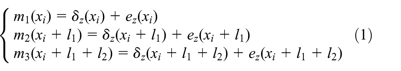
Figure 8 gives the yaw error derived from equation (10). In order to verify the estimated result of the method, the measured result of the yaw error is obtained through the normal method of angle measurements by an angular measurement kit of Renishaw XL-80 laser interferometer. A comparison test of the calculated yaw error with the measured yaw error is shown in Figure 8. The two results are seen to be similar to each other. Compared with the measured result of the yaw error, the calculated result of the yaw error has only varied little in amplitude, which may be affected by the motion error in yaw error measurement.
Comparison of the calculated yaw error with the measured yaw error.
Conclusion
A novel measurement method called laser interferometry–based method is proposed to obtain the straightness and the yaw errors of the slide motion accurately and simultaneously, which combines the advantages of both the laser interferometry technique and the shifting method. Experimental results confirmed the feasibility of the proposed method. Furthermore, the comparison test between the calculated yaw error and the measured yaw error is verified by the accurate measurement of the proposed method. This method reduced the difficult and complex adjustments in contrast to the traditional laser interferometry. The effects caused by the assembly error and movement of the reflector are reduced.
Footnotes
Academic Editor: David R Salgado
Declaration of conflicting interests
The authors declare that there is no conflict of interest.
Funding
This study is financially supported by the National Natural Science Foundation of China (51175221 and 51475208).