
Abstract
In this article, an aerostatic thrust bearing with annular elastic uniform pressure plate structure was designed. In order to obtain a relationship between bearing capacity and stiffness of aerostatic thrust bearing designed in this article, first, the stress field mechanics model of the gas thrust bearing was established in the static. Second, deformation control equations of the elastic uniform pressure plate and gas lubrication Reynolds equation were established according to the flow continuity principle. Here, finite element mesh of gas flow field was woven using the technology of grid overlapping and grid stitching. Then, gas–solid coupling control equations were solved using the numerical method. Gas film pressure distribution and gas static bearing capacity of thrust bearing were analyzed. Function relationship between bearing capacity and the stiffness and the thickness of gas film was obtained. Finally, the results of theory analysis and experiment were compared. The results of the comparison can be listed as, under the effect of gas pressure, orifice area and the equilibrium pressure groove depth are changed due to elastic deformation of the elastic uniform pressure plate. The static stiffness of aerostatic thrust bearing with elastic equilibrium pressure groove increased by 30% than the static stiffness of aerostatic thrust bearing with rigid equilibrium pressure groove. The maximum carrying capacity occurred in the gas film thickness of 3.5 µm. The maximum static stiffness appeared in the gas film thickness of 5.5 µm. It can be seen from the comparison results of experiments and theoretical analysis that data results of gas film thickness and the bearing capacity are the same. The feasibility of the theoretical analysis method is validated.
Keywords
Introduction
Stiffness, precision, and stability of the aerostatic thrust bearing are endowed with higher demand because of the development of precision and ultraprecise technology. But improving the stiffness of gas bearing is a very difficult task due to the compressibility of gas. Therefore, improving the stiffness of aerostatic thrust bearing and the hot spot of research field of aerostatic bearing is difficult.
Because most of the traditional aerostatic thrust bearings use restriction choke with holes, torus, and slit choke, increasing the bearing capacity and stiffness of aerostatic thrust bearing is very limited. Feedback control was carried out on the stiffness of aerostatic thrust bearing, which is an effective way to achieve high stiffness and infinite static stiffness. A lot of research has been carried out both at home and abroad in the recent years.
Du et al. 1 studied the influences of structural parameters of pressure-equalizing grooves (PEGs), such as the length, depth, number, and location, on the load capacity and stiffness system. Zhang and colleagues2,3 studied the performance of the variable equalizing pressure groove of aerostatic thrust bearing. Sun et al.4,5 analyzed the static pressure characteristics of gas bearing supersonic flow field. Shigeka et al. 6 analyzed the bearing performance of the hydrostatic bearing including numerical calculation and stress distribution. Zhang and Liu. 7 analyzed the film choke action of the mixed radial gas bearing properties. Xia et al. 8 analyzed the gas membrane flow field of the wave foil equation gas bearing. Toshiyuki and Yuya 9 present a new method for processing the air bearings. Lu and Wei 10 carried out the numerical calculation for static characteristics of gas floating pressure bearing and experimental study. There are also some other scholars who have carried out relevant research on aerostatic bearing performance.11–42
Mostly, previous studies have adopted rigidity equalizing pressure groove structure and could not effectively improve the stiffness of aerostatic thrust bearing.
Therefore, in order to improve the stiffness of aerostatic thrust bearing, a new type of high-stiffness aerostatic thrust bearing is designed in this article.
Bearing face of the new type of high-stiffness aerostatic thrust bearing uses the elastic uniform pressure plate. The variable cross-sectional equilibrium pressure groove can be realized. Cross-sectional area of the equilibrium pressure groove is changed with the change in gas film clearance or the corresponding pressure distribution changes.
Static performance of the equilibrium pressure groove of elastic homogeneous aerostatic thrust bearing plate is analyzed in this article. The feasibility of the theoretical analysis method is validated by the experiment.
Work principle
A high-stiffness aerostatic thrust bearing with variable equilibrium pressure groove structure (shown in Figure 1) is put forward and designed in this article. Bearing face of aerostatic thrust bearing adopts an annular elastic uniform pressure plate structure.
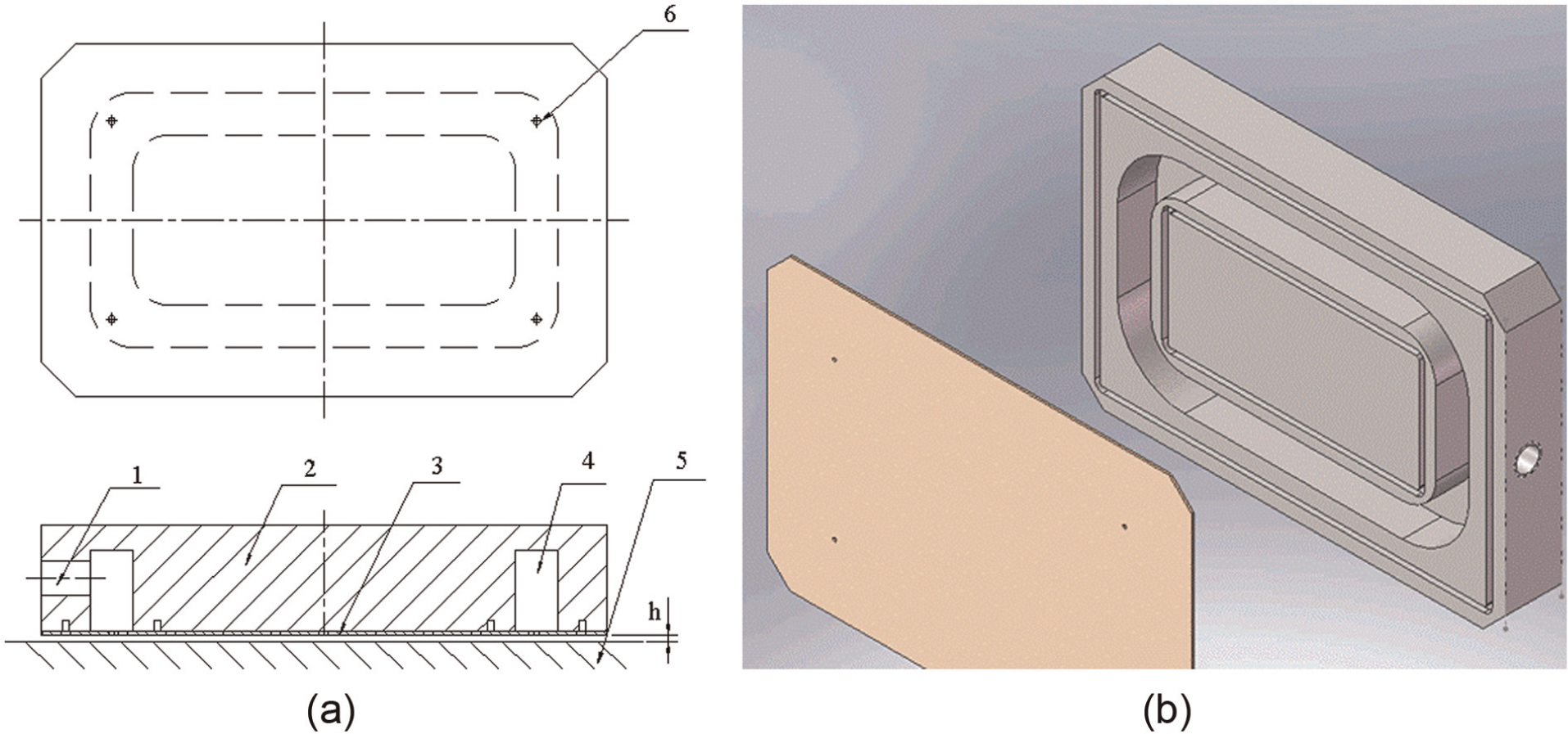
Structure diagram of aerostatic thrust bearing with elastic uniform pressure plate: (a) 2D structure diagram and (b) 3D structure diagram.
The annular elastic uniform pressure plate generated elastic deformation due to the influence of the gas film pressure. Elastic deformation caused the changes in the depth of the equilibrium pressure groove. Thereby, it will achieve the purpose of improving the stiffness of aerostatic thrust bearing.
Four corners of aerostatic thrust bearing were set as four orifices (nozzle orifices). Orifice exports and elastic equilibrium pressure groove are connected by the annular elastic equilibrium pressure groove. Figure 1(a) is a two-dimensional structure diagram, and Figure 1(b) is a three-dimensional entity model.
The working principle of aerostatic thrust bearing with the elastic uniform pressure plate can be stated as follows:
The gas is input into the aerostatic thrust bearing through air inlet 1. Pressure gas film is formed by the gas from orifice 6 to work surface 5. If the load increases or reduces, the elastic uniform pressure plate 3 will be concave or convex along the direction of groove chamber 4. Torus throttling area of orifice 3 will change and form the equilibrium pressure groove with variable depth. Finally, it can improve the stiffness of aerostatic thrust bearing.
Within the manufacturing process of aerostatic bearing, the gas pressure P 1 in the chamber makes the bearing surface convex outside the elastic thin plate. When the processing is complete, under the natural state, elastic deformation on the surface of the aerostatic bearing hollows in the initial equalizing pressure groove. Within the groove width and aerostatic bearing chamber, the width is consistent and groove depth is related to the size and position of P 1.
The working principle of the aerostatic bearing is shown in Figure 2. When the aerostatic thrust bearing works, its air-cavity is full of gas with certain pressure of Ps.
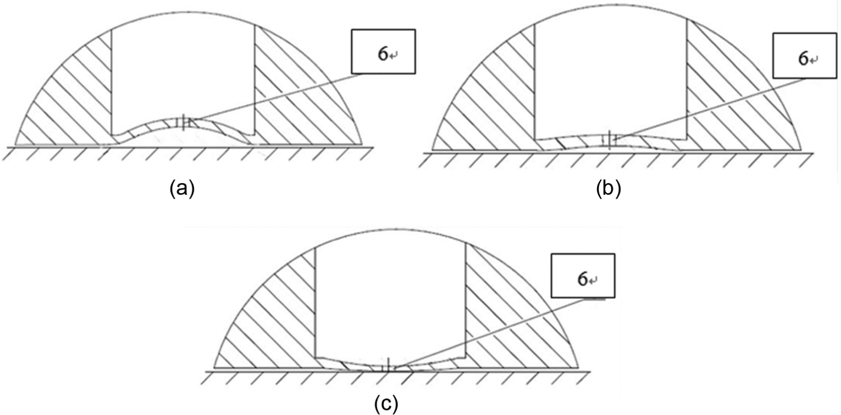
The diagram of elastic thin plate deformation: (a) elastic thin plate deformation with a large load, (b) elastic thin plate deformation with a medium load and (c) elastic thin plate deformation with little load.
As seen in Figure 2(a), when the load is increased, the equilibrium pressure groove produces concave deformation under uniform elastic thin plate under the action of pressure. The bearing capacity of the aerostatic thrust bearing increases along with the change in the equilibrium pressure groove. The height of the throttling orifice ring surface increases, and the restriction area of the throttling orifice 3 increases. After throttling, the pressure of the gas further increases and the bearing capacity of the aerostatic thrust bearing improves.
When the load decreases, as seen from Figure 2(b), concaved deformation of the equilibrium pressure groove decreases under uniform elastic thin plate under the action of pressure. The bearing capacity of the aerostatic thrust bearing decreases along with the change in the equilibrium pressure groove. The throttling ring surface height decreases, the throttling mouth area decreases, and the pressure reduces. The carrying capacity of the aerostatic thrust bearing continues to reduce. If the load is further reduced, due to the gas supply, pressure Ps is much larger than pressure P 1. Due to the too much bending stress of elastic thin plate, the equalizing pressure groove will produce outer convex deformation. As shown in Figure 2(c), the stiffness of the aerostatic thrust bearing may appear negative, and its carrying capacity is almost lost. Here, the aerostatic thrust bearing stiffness may reach a great value of dw(h)/dh → ∞.The application range of the aerostatic thrust bearing will be greatly expanded.
Static mathematical model
Control equation of elastic thin plate deformation
By the theory of plate and shell, 27 the deflection of the plate is very small. The deflection can be shown in the following formula

Here,

Here, E is Young’s modulus and
A parallel piped infinitesimal is taken from the plate; the length of the three sides is

Here,
Transverse shear is
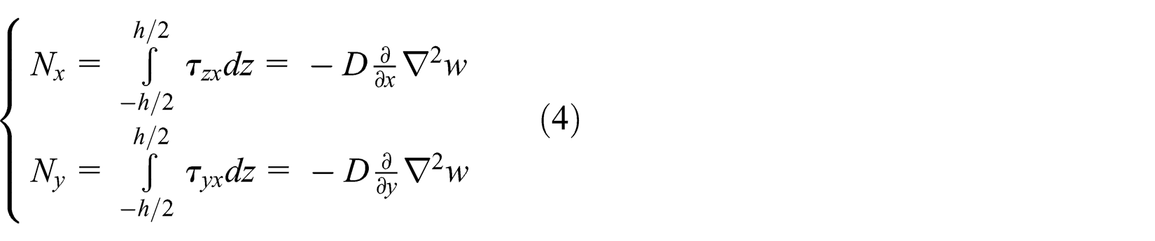
The equilibrium equations of the plate are

Here,
Due to the characteristics of the new structure aerostatic thrust bearing with the annular elastic uniform pressure plate, the theoretical analysis becomes more complex between the gas film clearance and bearing capacity. For aerostatic thrust bearing shown in Figure 1, deformation control equation of the elastic uniform pressure plate in the rectangular coordinate system is shown in the following formula 3
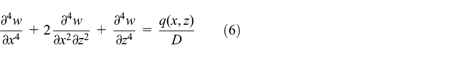
Here, w is the deflection of the vertical direction of the gas film, q (x, z) is the distributed load, and D is the bending stiffness of the elastic uniform pressure plate.
Formula (6) is discrete computation using the finite difference method. At the same time, the use of difference scheme of secondary accuracy, elastic thin plate deformation, is as follows
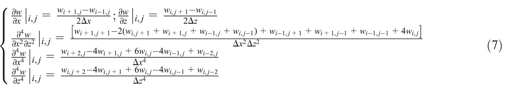
Here, i and j are the grid line numbers of x- and z-directions, respectively; Δx and Δz are the distance of the grid line for the x- and z-directions, respectively.
The difference scheme of equation (7) is substituted into control equation (6) of the thin elastic deformation. Next, the difference equation of node (i, j) is obtained and can be expressed as equation (8). Here, A1(i, j), A2(i, j), and A3(i, j) are associated with w(i, j)
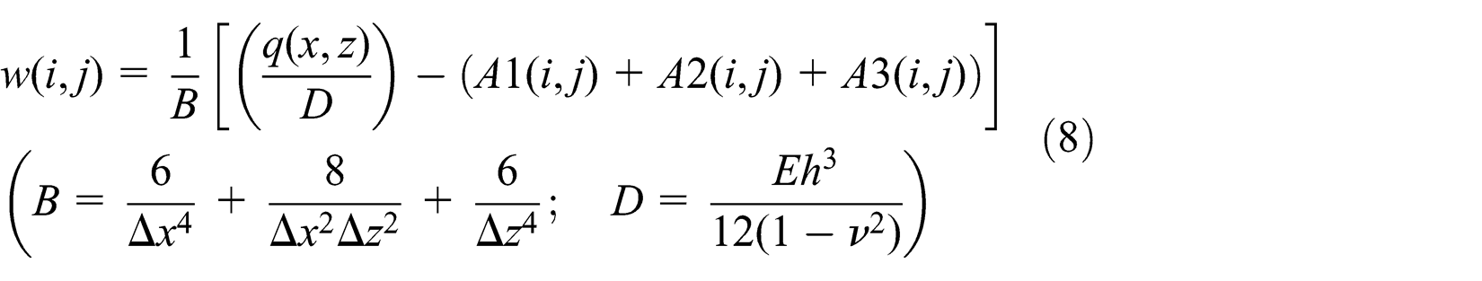
Formula (7) was calculated using the successive linear over-relaxation (SLOR) method, and then iterative formula (8) 11 will be obtained

Here, α is the accelerating convergence coefficient; generally, α is 1 < α < 2.
Gas lubrication control equation
The various performance parameters of the aerostatic thrust bearing are mainly calculated based on Reynolds equation. Under the rectangular coordinate system, gas lubrication control equation can be represented as formula (10)

Here, µ is the air viscosity and h is the loading gas film clearance.
Due to the structure of equalizing pressure groove, the loading gas film clearance (h) is the function of x, z coordinate. Therefore, the loading gas film clearance (h) could not obviate from Reynolds equation.
The loading gas film clearance h of formula (10) can be expressed as follows

Here, h 0 is the gas film clearance of the loaded plane and w(x, z) is the depth of the elastic equalizing pressure groove, and it can be obtained by formula (8).
It is assumed that f = p 2; formula (11) is carried on the finite difference and can be expressed as formula (12)
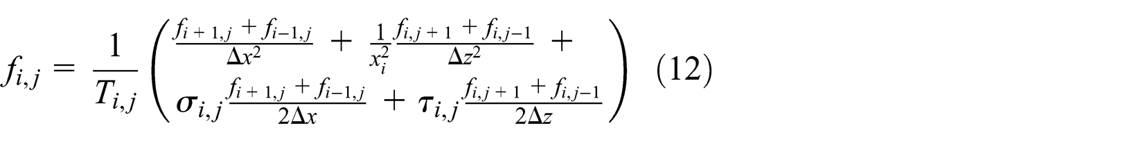
Here,
Formula (12) is solved by the iteration method. Its iterative formula can be expressed as formula (13)

Here,
The real working state of the aerostatic thrust bearing with the elastic uniform pressure plate is a coupled result of gas lubrication control equations and elastic uniform pressure plate deformation control equations by h(x, z).
In the orifice exit, pressure boundary condition of Reynolds equation of aerostatic thrust bearing can be expressed as follows

Here,
Then, the bearing capacity of the aerostatic thrust bearing can be obtained as follows

According to the rigidity definition, the stiffness of aerostatic thrust bearing can be expressed as

The greater the stiffness value, the superior the aerostatic thrust bearing performance.
The calculation process is shown in Figure 3. The deformation of elastic uniform pressure thin plate is calculated by the condition of the difference value between the supply gas pressure and bearing surface gas pressure. Then, the deformation of elastic uniform pressure thin plate will be considered as known conditions for calculating the gas pressure of bearing surface. Next, through repeated calculation, when the coupling accuracy is in the range of reasonable accuracy, it shows that the coupling calculation is complete.
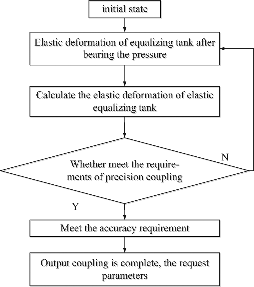
Static coupling calculation flow chart of aerostatic thrust bearing.
In order to give an iterative initial value of the actual equilibrium pressure groove depth in aerostatic thrust bearing, the minimum location of working clearance will be the starting point. It is assumed that the minimum working clearance is h min. The fluid impedance of working clearance, the load, the deformation of the equalizing pressure groove, and the cross-sectional area of the equalizing pressure groove are biggest.
Calculation examples
The parameters’ aerostatic thrust bearing with the elastic uniform pressure plate is expressed in Table 1.
Parameters related to the bearing.

The working surface of aerostatic thrust bearing is divided into a grid, which is represented in Figure 4.
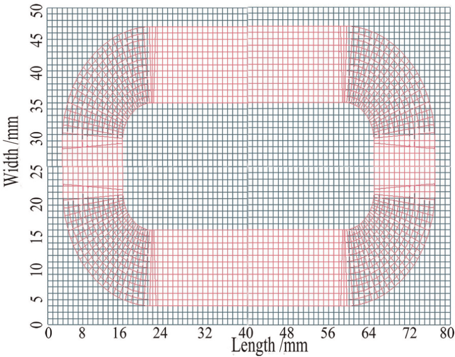
Mesh generation of aerostatic thrust bearing.
Here, the deformation of elastic plate is divided into a grid according to rectangular coordinates and polar coordinates. Gas film pressure distribution is divided into a grid according to rectangular coordinates. The overlapping region of the two kinds of grid adopted double linear interpolation to calculate message.
The finite difference method is used to carry out numerical calculation of the aerostatic thrust bearing with the elastic uniform pressure plate, using the coupling calculation flow chart shown in Figure 3 and based on the elastic uniform pressure plate structure and parameters of the aerostatic thrust bearing of Table 1.
Figures 5–7 are the three-dimensional simulation diagrams of the deformation of elastic thin plate elastic and gas film pressure distribution at gas film thicknesses of 3.5 µm (maximize capacity), 5.5 µm (maximize stiffness), and 8.5 µm (bearing capacity rapidly drops), respectively.

Equalizing groove deformation diagram and gas film pressure distribution under the gas film thickness of 3.5 µm: (a) equalizing pressure groove deformation and (b) gas film pressure distribution.

Equalizing groove deformation diagram and gas film pressure distribution under the gas film thickness of 5.5 µm: (a) equalizing pressure groove deformation and (b) gas film pressure distribution.

Equalizing groove deformation diagram and gas film pressure distribution under the gas film thickness of 8.5 µm: (a) equalizing pressure groove deformation and (b) gas film pressure distribution.
As seen in Figure 5(a), the deformation of the equalizing pressure groove of elastic thin plate is uniform. The gas sealing effect is good. As shown in Figure 5(b), pressure distribution in the central area is almost equal to the outlet pressure of the orifice. The bearing capacity of the aerostatic thrust bearing is in the biggest stage.
It can be seen from Figure 6(a) that the deformation of the equalizing pressure groove of elastic thin plate is not uniform. Here, the deformation of the long side of the central is small. Gas sealing effect is decreased. As shown in Figure 6(b), the pressure of the center area is obviously decreased, and the bearing capacity is in the fallen fastest stage. The maximum stiffness of aerostatic thrust bearing is at the gas film thickness of 5.5 µm.
It can be seen from Figure 7(a) that the deformation of the equalizing pressure groove of elastic thin plate is not very uniform. Here, the deformation of the long side of the central is of negative value. The effect of sealing gas is lost. As shown in Figure 7(b), the pressure of the center area is nearly lost, and the bearing capacity is equivalent to not equalizing pressure groove.
According to the above analysis, the performance of the two kinds of aerostatic thrust bearing (with the elastic uniform pressure plate and without elastic uniform pressure plate) is analyzed at the supply gas pressure of P = 0.65 MPa. The results of the performance are as shown in Figure 8.

The contrast curve of the bearing capacity and rigid of the two kinds of aerostatic bearing: (a) bearing capacity curves and (b) stiffness curves.
As seen in Figure 8(a), the bearing capacity of the aerostatic bearing with elastic thin plate variable equalizing pressure groove is lower than the bearing with rigid equilibrium pressure groove. But Figure 8(b) shows that the stiffness of the new type of aerostatic bearing is better than the bearing with rigid equilibrium pressure groove at the working gas film thickness of 6 µm.
Through the above analysis, the feasibility of using the elastic thin plate variable equalizing pressure groove to improve the bearing stiffness is theoretically verified. Therefore, from the theoretical analysis, the bearing stiffness of the new structure aerostatic bearing designed in this article will get a breakthrough.
Experimental research and model validation
In this section, experimental research of the aerostatic thrust bearing with annular elastic uniform pressure plate is carried out. Then, an experimental comparison and analysis between the aerostatic thrust bearing with elastic uniform pressure plate and the one of the original rigid equilibrium pressure groove are performed. Next, relationships between the stiffness and bearing capacity of the new type of aerostatic thrust bearing are obtained. The processing of high-stiffness aerostatic thrust bearing is shown in Figure 9.

Processing of high-stiffness aerostatic thrust bearing: (a) grind and (b) electro-sparking of elastic uniform pressure plate.
The global design of the experimental bench is shown in Figure 10.

Global structural layout of the experimental bench: (a) schematic diagram and (b) experimental bench.
The experimental bench is mainly to measure the static property of the aerostatic thrust bearing, including the static bearing capacity, gas film clearance, pressure distribution, and gas consumption. The experimental bench is divided into three aspects, including loading system, working platform, and testing system.
Loading system design
The loading system of this experiment bench uses the spring-loaded principle, which can realize continuous and stable loading and is easy to operate. The assembly structure of the loading system is shown in Figure 11.

Assembly drawing of loading system: (a) schematic diagram and (b) loading system.
The loading system mainly includes scissor jacks, stretching the spring, press reset spring, loading rod, loading head, and gas floating guide. This design will use ZYA15-type electric scissor jacks to applying device for the loading system.
In the process of testing, the external slight disturbance will affect the accuracy of the experimental results. For this purpose, the moving part of the loading system uses the gas floating guide rail. It can at the maximum reduce interference and improve test precision.
The gas floating guide consists of the guide rail and aerostatic thrust bearing. To achieve higher support stiffness, the aerostatic thrust bearing adopts symmetrical arrangement in fully enclosed structure. The structure is displayed in Figure 12.

Arrangement of the aerostatic thrust bearing and gas floating guide: (a) schematic diagram and (b) gas floating guide.
The loading head is an installation structure of force transducer. For obtaining the loading head design, it should be able to accurately reflect the change in bearing capacity and minimize the interference of the mechanical structure of sensing devices. The loading head structure is shown in Figure 13.

Loading head structure.
Shaft 1 is inserted into the top flange and then connected to the loading bar, making the loading head and applying organization as a whole; loading head shell 3 is fixed to force transducer 4 and contact ball head 6; shaft 1 bottom and loading head shell 3 inner radial cavity have uniform 4 shallow groove. The shallow groove has filled four groups of high-carbon chromium bearing steel balls, to make the loading head shell, force transducer, contact ball heads, and shaft 1 as a V kinematic pair. Lock nuts are screw-thread fits with loading head thread, by adjusting the gasket compression. During the spinning process, four groups of steel ball are compressed. Make critical contact state and strain sensors to achieve.
Working platform design
Test bench work platform mainly includes two aspects. One is the benchmark platform and leveling equipment and the other is single-coordinate workbench and its positioning device. Benchmark platform chooses granite material. Single-coordinate workbench and positioning device are shown in Figure 14.

Single-coordinate workbench and positioning device.
Benchmark platforms connect single-coordinate workbench through bolt, fixed two test bench scale 4, positioning bracket is installed on a positioning pin 5. Locate the Y-axis, first, rotating elastic screw 2, after mobile positioning bracket 1 to specify the location (through scale positioning), the screw tight set screw 2; the screw is loosed to the T-slot bolt. It moves the single-coordinate workbench to rely on tight two positioning pins; finally, the screw tightens T-slot bolt to complete orientation.
Test system design
Aerostatic thrust bearing performance test bench is to test the performance of the four static bearings, including the bearing capacity, gas film thickness, pressure distribution, and gas consumption.
Bearing capacity test
In order to more accurately test the actual bearing capacity of the gas bearing, bearing force transducer should be close to the gas. The installation structure of the force transducer is shown in Figure 12, meanwhile, using micro-force transducer.
Gas film clearance measurement
Gas film clearance measuring element is the capacitive micrometer. The experiment in gas bearing surface lightly crossed and use the micrometer three measuring heads, as shown in Figure 15.

Micrometer three measuring head positions.
Knowledge on space geometry, of three points in space M 1(x 1,y 1,z 1), M 2(x 2,y 2,z 2), and M 3(x 3,y 3,z 3), helps to determine the equation of a plane. First, find out the normal vector to the plane. As a result of the normal vector n and vector M 1 M 2, M 1 M 3 are vertical, M 1 M 2 = {x 2−x 1, y 2−y 1, z 2−z 1,}, M 1 M 3 = {x 3−x 1, y 3−y 1, z 3−z 1,}, the vector product of n is

Remember n = (A, B, C), according to the points in the plane of the French formula, using known as three point (e.g. M 1 point) to get the coordinates of plane equation is

To determine the equation of a plane bearing center X, Y coordinate values into the equation of a plane, and it can get to the value of the gas film thickness, which is ultimately the gas film thickness of the experimental value.
Pressure distribution test
Choose resistance-type pressure gauge testing components. Measuring the bearing pressure distribution within the bearing clearance, pressure plate fixed in single-coordinate workbench, control table in track step by step according to the prescribed direction. Workbench mobile distance in the X- and Y-directions can be read from the corresponding axis positioning device so as to determine the corresponding coordinates’ measuring holes on the pressure plate; at the same time read the corresponding coordinates far east one pressure gauge on the display value, you get a discrete point in the pressure distribution data.
Gas consumption measurement
Choose V cone flowmeter test, gas consumption experiment in the test gas floating cushion between air supplies and install V cone flowmeter, the use of the devices to measure gas consumption in the process of experiment. Compared with other flowmeters, V cone flowmeter has high accuracy, good stability for a long time, installation condition limits small and wear resistance, wide measuring ranges, and suitable for the advantages of smudges.
Model validation
It is use the test bench to elastic thin plate variable equalizing pressure groove aerostatic bearing under different air supply pressure. It will give the contrast test of elastic thin plate aerostatic bearing under different gas pressures; only gas film thickness changes. The experiment result is shown in Figure 16:

Experimental analysis under different air supply pressures.
The supply gas pressure is P = 0.60 MPa. The stiffness of aerostatic bearing is decreased, due to the elastic thin plate being in a state of concave when the gas pressure is equal to 0.65 MPa. The elastic thin plate is in an initial state (gas film thickness is more than 10 µm); the bearing capacity is lower when the supply gas pressure is equal to 0.60 MPa. If the load is unceasingly increased, the film thickness is less than 10 µm, and the elastic thin plate will be concave mutation. The stiffness is rapidly increased. The bearing capacity is also increased accordingly.
If the supply gas pressure is equal to 0.65 MPa, the results of the experiment and numerical analyzing calculation are shown in Figure 17:

Results of numerical calculation and experiment.
It can be seen from Figure 17, under static condition, that the theoretical calculation value and experimental value of the elastic uniform pressure plate of aerostatic thrust bearing are consistent. Thus, it is good enough to validate the correctness of the theoretical calculation.
Through theoretical calculation and experimental research, there are some differences of aerostatic thrust bearing in the process of machining. There exists a certain roughness surface, so machining accuracy cannot be neglected in the influence on the performance of the aerostatic thrust bearing. This makes the theoretical calculation and experimental results will be unavoidably existed certain differences. In the process of experiment, the gas has a slight leakage phenomenon, which will lead to the actual work of gas supply pressure being slightly less than the given gas supply pressure. The bearing capacity will also be reduced.
Conclusion
In this article, our team has put forward and designed a new type of high-stiffness aerostatic thrust bearing with the annular elastic uniform pressure groove. Through the numerical simulation analysis, the mechanical characteristics of the aerostatic bearing are obtained. The conclusions are as follows:
Through the numerical simulation analysis, it is can be shown that the bearing capacity of the new type of aerostatic thrust bearing with the annular elastic uniform pressure groove is lower than the aerostatic thrust bearing with rigid equilibrium pressure groove. However, there is a best clearance; the stiffness of the new type of aerostatic thrust bearing can increase by 30% than the aerostatic thrust bearing with rigid equilibrium pressure groove.
Test bed is designed using the spring pull pressure balance principle, to realize the continuous and stable loading. The loading rod and its surrounding gas guide maximum limit reduce the interference from the outside. Force sensor installed at the loading head bottom, loading head shell, force transducer, contact ball head, and shaft 1 can timely and accurately reflect the change in force and improve the test accuracy.
The structure of the elastic equilibrium pressure groove and the position of the aerostatic thrust bearing have greater influence on the overall performance of the bearing. Through the comparison of the experimental and numerical results, it effectively verifies the accuracy of numerical calculation. For the research and development of aerostatic thrust bearing, it will provide a new structure and new way of thinking.
Footnotes
Academic Editor: Yunn-Lin Hwang
Declaration of conflicting interests
The authors declare that there is no conflict of interests regarding the publication of this article.
Funding
The authors would like to acknowledge the support by the National Natural Science Foundation of China (51375384) and the Research Foundation of Education Bureau of Shaanxi Province, China (12jk0692) and special research projects of Shaanxi province education department, China (Dynamic load-sharing characteristics research on the face gear power split drive system based on tooth surface micro modification technology).