
Abstract
Numerical models have been developed by commercial package Fluent 6.3 to simulate the air flow through single dimple, simple, and dimpled louvers in low and medium Reynolds numbers. Experiments have also been conducted to measure the temperature and heat transfer in these geometries. Heat transfer augmentation of 8% has been observed by implying dimples on louver at the same mass flow rate. For accurate investigation of the effect of dimple, a single dimpled surface has been modeled numerically and experimentally. The simulation revealed that these heat transfer and temperature augmentations occur due to existence of a circulation region created by dimple. Additionally, the effects of louver’s thermal resistance on temperature distribution over the louver surface have been considered to gain the actual contours. Continuous temperature gradients have been observed over the louver surface with the highest temperature at the base of the louver and the lowest temperature at the middle of the louver. Louver efficiency has been introduced to assess the dimpled louver performance for low and medium Reynolds numbers. It has been observed that dimpled geometry has satisfactory louver efficiency. Good agreement has been observed between experimental and numerical models.
Keywords
Introduction
The variety of applications of compact heat exchangers in automotive; heating, ventilation, and air conditioning (HVAC); refrigeration; and other industries has made it necessary to enhance their performance. This could be done by altering the heat exchanger’s geometrical characteristics and the flow regime. One of the most common ways to enhance the heat transfer of compact heat exchangers is to use interrupted surface. Many numerical and experimental attempts have been made to improve the heat transfer of compact heat exchangers by dimples and multi-louvered fins. Beauvais 1 performed flow visualization experiments on the louvered fin array as the first study in this area. He showed that louvers actually redirect the flow between them. Flow visualization reported by Davenport 2 demonstrated two asymptotic flow regimes: duct-directed flow and louver-directed flow. In the former, the predominant flow is streamwise, while in the latter, the predominant flow is aligned with the louvers. Zhang and Tafti 3 showed that the flow direction has a significant effect on the overall heat transfer of the fin. Therefore, it is important to be able to quantify the flow regime. In order to do so, a parameter called “flow efficiency” is defined as the degree to which the flow is aligned to the louver direction.4–6 A 100% efficiency represents complete louver-directed flow, while 0% represents complete duct flow. 3 Achaichia et al. 5 studied the flow pattern in this geometry with a k-epsilon turbulence model for high Reynolds numbers. However, high Reynolds turbulence models are not very accurate in unsteady laminar and low Reynolds number turbulence regimes encountered in compact heat exchangers. Zhang et al.6,7 and Tafti et al.8,9 have studied the effects of flow oscillations in the form of large-scale vorticity on the heat transfer coefficient. In addition to interrupted surface concept of louvered fins, continuous fins like dimpled surfaces have been proved to significantly enhance the heat transfer capacity of compact heat exchangers. The use of dimpled surfaces has received attention due to their good heat transfer characteristics and low pressure drop penalties compared to interrupted surfaces. 10 Afansayev et al. 11 studied the effects of shallow dimples on flat plates on the overall heat transfer capacity and pressure drop. They reported a significant heat transfer enhancement (30%−40%) at a low pressure drop cost. Ligrani et al.12,13 experimentally investigated the flow structure in dimpled surfaces and showed the existence of flow recirculation zone in the upstream half of the dimple. Wang et al. 14 observed a symmetric three-dimensional (3D) horseshow vortex inside a single dimple using laminar flow simulations. Lin et al., 15 Isaev and Leont’ev, 16 Park et al., 17 Won and Ligrani, 18 and Park and Ligrani 19 investigated the flow structure and heat transfer in dimpled channel in fully turbulent regimes using steady-state Reynolds-averaged Navier–Stokes (RANS) models. Patrick and Tafti 20 investigated the problem in low Reynolds numbers (Re = 50–2000) using direct numerical simulation (DNS) and large eddy simulation (LES). Recently, new fin geometries have been studied in which the dimples are implied on the louver surface to take advantage of the characteristics of louvers and dimples at the same time. Elyyan and Tafti 21 investigated the flow and heat transfer characteristics of dimpled multi-louvered fins. They reported not only significant heat transfer augmentation but also considerable amount of friction loss augmentation through dimpled louvers. They also showed that implying perforation on dimples has a sharp impact on heat transfer augmentation. In another numerical study, 22 they introduced a novel geometry which was the result of altering the dimple shape. Higher values of heat transfer and friction loss were reported for this geometry. They have also reported that the turbulence levels increase by the shear layer induced by their new geometry’s split-dimples. Shokuhmand and Sangtarash 23 conducted experimental and numerical studies on the heat transfer and flow efficiency of multi-louvered fins. They reported that implying dimples and perforated dimples on the louvers enhances the heat transfer and flow efficiency significantly.
In this study, we deepen our focus on a pair of dimpled louvers of the multi-louvered fin bank on which we investigated the heat transfer and flow efficiency of the entire geometry in another research. 24 The heat transfer and temperature distribution over the louver surface are studied. Moreover, we take into account the effect of louver conductive thermal resistance on heat transfer in low Reynolds numbers. We also introduce the term louver efficiency to evaluate the effectiveness of implying dimples on louver.
Objective
In this study, the effects of implying dimples on louvers have been investigated by examining the performance of a pair of simple and dimpled louvers. Former studies on this geometry have studied the Nu number augmentation, temperature gradient, and friction loss over the louver surface. They have also simulated the problem by constant heat flux assumption over the louver’s surface. Here, we consider the effects of conductive thermal resistance of the dimpled louver’s material and assess the dimpled louver performance by investigating the heat transfer, temperature distribution, and dimpled louver efficiency. The flow regime is laminar and early transient. The computational model is compared with the experimental data and numerical reports found in the literature. This work would lead to investigation of the entire dimpled multi-louvered fin bank by implying the method to the whole geometry.
Characterization of heat transfer
In this section, we characterize the heat transfer by defining Nu and louver efficiency for assessing and verifying the model. The convective heat transfer is defined as follows

where Q is the total heat transfer rate, A is the heat transfer surface area,

And the dimensionless Nu number is defined as

where k is the thermal conductivity of fluid and L is the characteristic length which in this work is equal to fin pitch.
Furthermore, we divide the values of all heat transfer rates by the value of heat transfer rate of the flow with the minimum Re number for dimpled louver to compare the dimensionless values

To assess the effectiveness of implying dimples on louver, we introduce louver efficiency as the ratio of the actual total heat transfer rate of the louver to the maximum heat transfer rate that would exist if the entire louver surface were at its base temperature
Experimental and numerical methodology
Experimental methodology
A low-turbulence wind tunnel, Model No. TE.44/D manufactured by Plint and Partners Ltd, has been employed to gather data from the entire multi-louvered fins setup. The dimpled louver’s material is copper. The flow velocities have been set at the inlet of the test channel to reach the desired Reynolds number. A temperature controller circuit was designed to maintain the temperature at 100°C to maintain a constant temperature condition at both sides of each louver. The controller will verify the temperature 20 times per second to achieve a minimum deviation from the set point. An energy meter was used to verify the energy that is consumed to set the temperature of both sides of each louver to the set point value. A data-gathering system was designed to make online measurement of the temperature. The temperatures from needed zones on the surface of different louvers have been measured using thermal sensors to determine the Reynolds numbers. All values were recorded when the temperature of the measurement zone stabilized. Furthermore, a single dimpled surface has been constructed to measure the temperature of more points of the surface. The cross section of the measuring part of the tunnel is 460 × 460 mm2 and the length of the test section is 600 mm. Figure 1 shows the test section of our research. The louver sample made is shown in Figure 2. In both figures, the flow direction is from left to right.
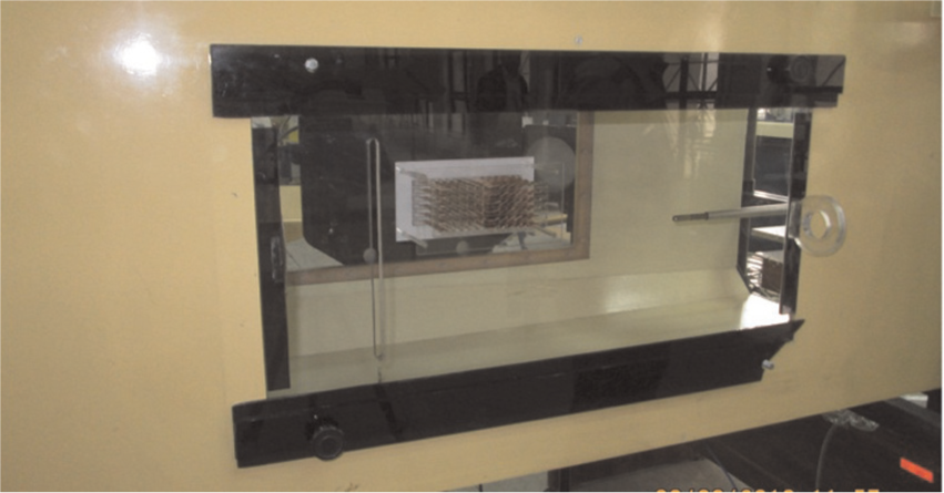
Test section; the flow direction is from left to right.
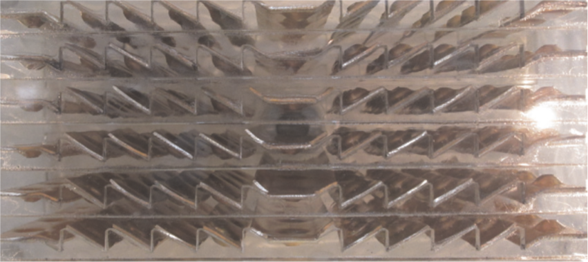
Louver bank sample; the flow direction is from left to right.
Numerical methodology
The momentum and energy equations were solved with second-order discretization. The commercial package Fluent 6.3 has been used to simulate the computational 3D models. Four geometries have been modeled to gain the results for computational fluid dynamics (CFD) predictions. Case 1 is a domain with the same dimensions as those in Elyyan and Tafti. 21 Case 2 consists of a pair of dimpled louvers with the same dimensions as those in the experimental setup of this work. Case 3 consists of the louvers of Case 2 without dimples. In Case 4, a single dimple is modeled with the same size as that investigated experimentally in this work to assess the flow with more details. Suitable grid sizes have been chosen among the number of grids to gain the most accurate results with less time consumption for convergence. Figure 3 shows the four cases and Table 1 gives their dimensions. To reduce the domain size, half of the domains are modeled and the results for the other half are gained by implying the symmetry boundary condition on the middle surface of the entire domain. The inlet velocity at the upstream and outflow at the downstream of the louvers have been set as the boundary conditions. The constant temperature boundary condition has been implied on the wall at the base of the louvers. The properties of air as the fluid and copper as the louver material are shown in Table 2. Furthermore, conduction heat transfer through the louvers has been simulated while the couple boundary condition has been implied for the louver surface where fluid and solid zones share surface. The LES method has been used to model the early transient regime. The dynamic Smagorinsky model is activated only when the turbulence flow is generated.
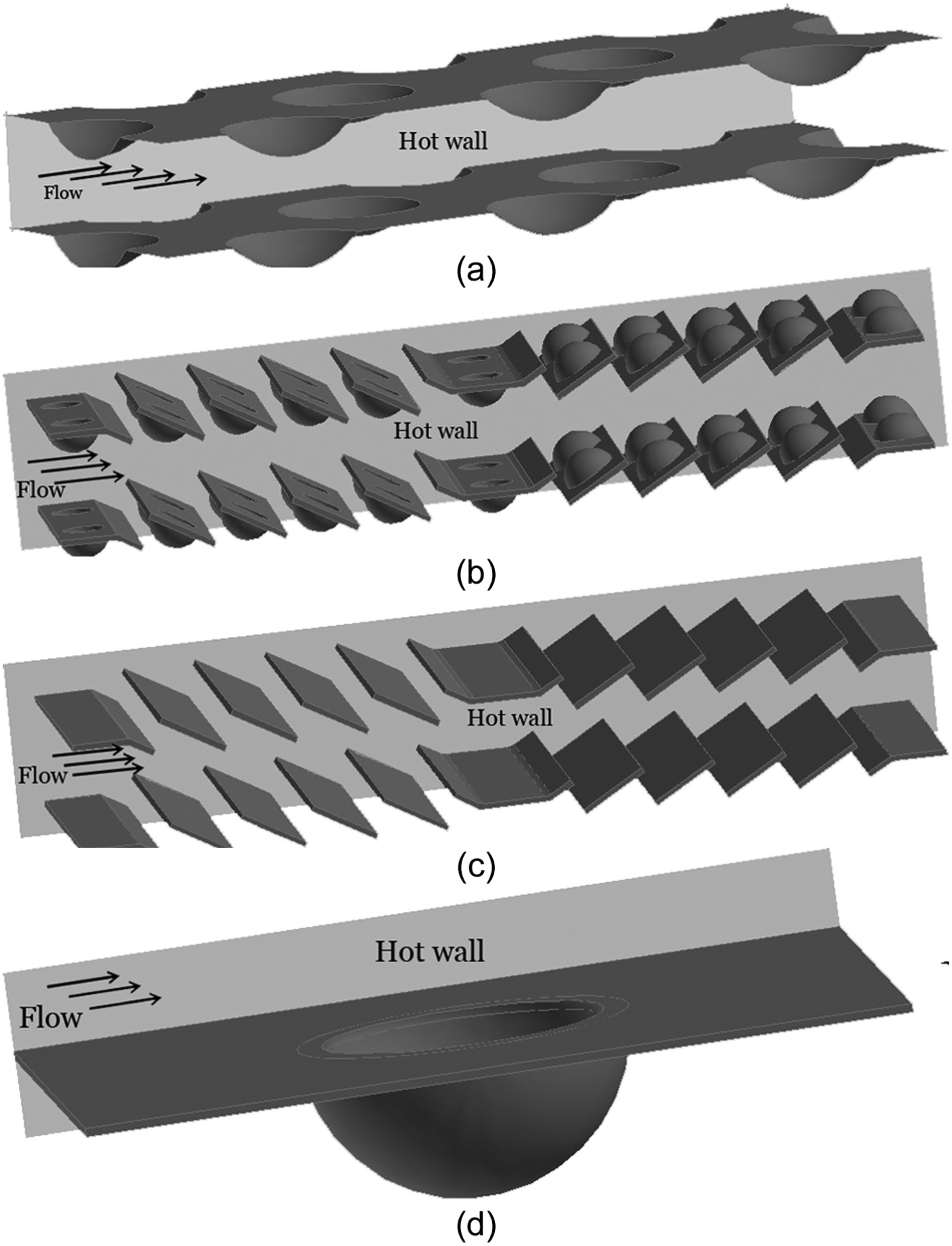
Schematic view of (a) Case 1, (b) Case 2, (c) Case 3, and (d) Case 4.
The size of four geometries.

The properties of air and copper assumed for modeling.

Validation
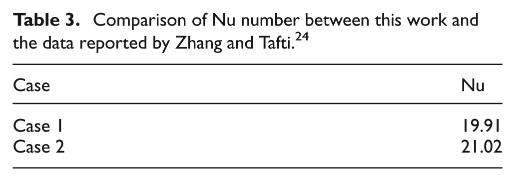
To validate the computational model, the results have been compared to the data reported in the literature. Elyyan and Tafti 21 characterized the heat transfer by Nu number. Figure 4 depicts the amount of average Nu number over the surface in Case 1 of this study and in the data reported by Elyyan and Tafti. 21 An agreement between these two models with error less than 3% is found. Zhang and Tafti also investigated the heat transfer over simple louvers. Table 3 gives the amount of average Nu number in Case 2 of this work and in the data reported by Zhang and Tafti 24 for the first louver with no wake effect in Reynolds 1000. Good agreement can be seen between these data with error less than 5.6%.
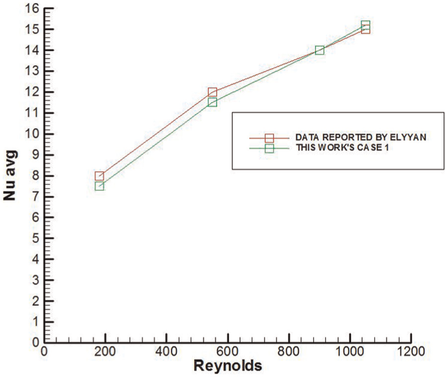
Comparison of Nu number between this work and the data reported by Elyyan and Tafti. 21
Comparison of Nu number between this work and the data reported by Zhang and Tafti. 24
Results and discussion
Heat transfer
Figure 5 shows the dimensionless total heat transfer rate for a pair of dimpled louvers and a pair of simple louvers for different Reynolds numbers. It can be seen that the heat transfer rate increases by implying dimples on the louver. Since the difference between the heat transfer rate of dimpled louver and simple louver increases by increasing the Re number, it can be inferred that the effect of dimples on heat transfer is more sensible in higher Re numbers. Case 4 has been used for detailed investigation of the effect of dimple on the flow’s hydrodynamic and thermodynamic characteristics. Figure 6 shows the contours of heat transfer coefficient over the dimpled surface in Case 4. As can be seen, the heat transfer coefficient has its maximum value at the beginning of the surface (where the maximum velocity and temperature gradients exist). The minimum heat transfer coefficient is observed at the upstream of the dimple surface, while its amount reduces considerably at the downstream of the dimple. These changes in the heat transfer coefficient occur due to the hydrodynamic characteristics of the flow over the dimpled surface. Figure 7 shows the path lines of flow in Case 4. A circulation region can be observed at the upstream of the flow. The existence of this circulation region leads to a reduction in the heat transfer coefficient. On the other hand, the disturbance in flow made by dimple intensifies the heat transfer coefficient at the upstream of the dimple. The temperature distribution through the fluid is seen in Figure 8. It depicts the growth of thermal boundary layer which is the effect of implying dimple on the surface.
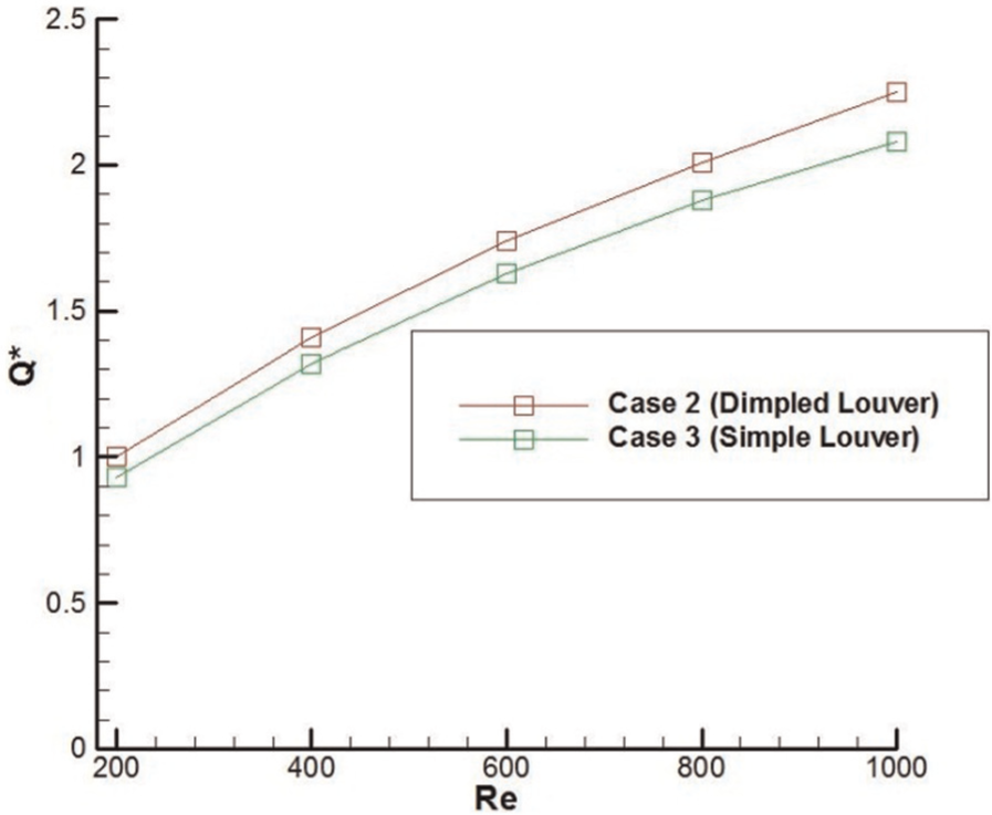
Dimensionless total heat transfer rate of Cases 2 and 3 for different Reynolds numbers.

Contours of heat transfer coefficient over the louver surface.
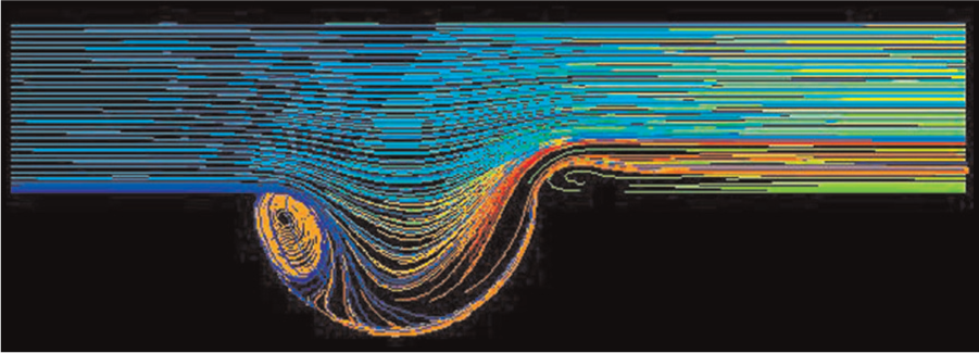
Path line of flow over the dimpled surface.

The temperature distribution through the flow over the single dimpled surface.
Temperature distribution
Almost all of the studies on this geometry assumed constant heat flux when investigating the effect of dimples on heat transfer enhancement. Since the actual heat source in this problem is the fluid flowing inside the tubes, we set the tube’s wall temperature as the boundary condition. In this work, we consider the effect of copper thermal resistance on the temperature gradient through the louver. The maximum temperature exists at the tube’s wall. Figure 9 shows the temperature distribution over dimpled louvers for Reynolds numbers 200 and 1000. It can be observed that the louver surface temperature decreases as the distance from the tube wall increases. It can also be seen that the wall temperature decreases with increase in Reynolds number. Figure 10 shows the temperature of the center of the dimpled louvers (numerical and experimental models). It detects that the louver surface loses more temperature by increasing the Reynolds number. The more the Reynolds number, the better the heat transfer. Consequently, louver transfers more heat and gets colder in higher Reynolds numbers. It also illustrates the difference of less than 3°C between computational simulation and experimental data.
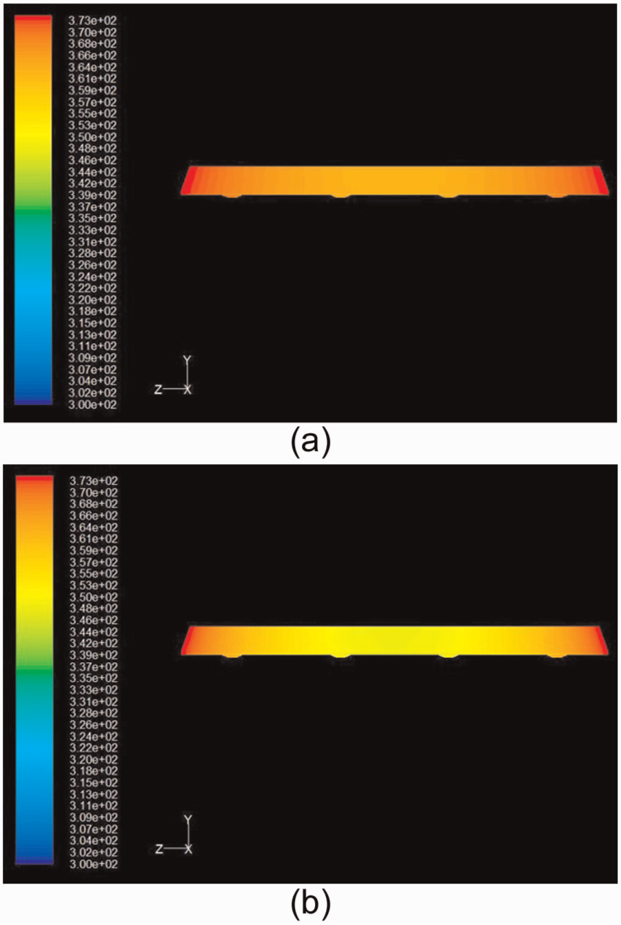
Temperature contours over the louvers’ surface: (a) Re = 200 and (b) Re = 1000.
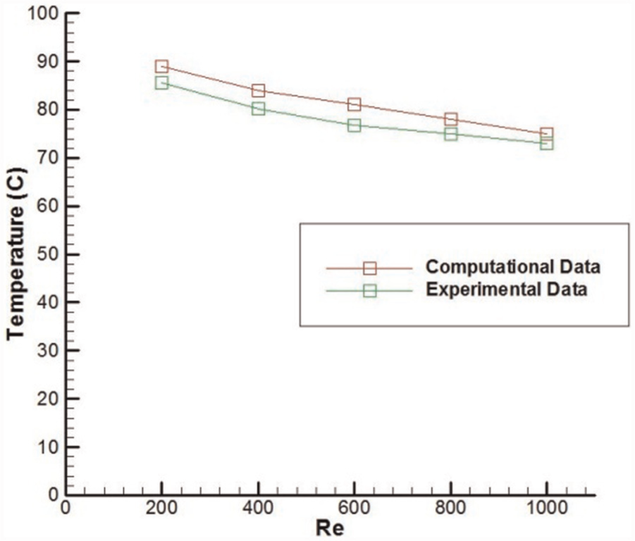
Temperature of center of the louver in Case 2 (numerical and experimental data).
Louver efficiency
The maximum heat transfer occurs where the maximum temperature difference exists. Hence, the ideal heat transfer situation for louvered fins would exist if the entire louver surface was at the tube wall temperature. Due to both thermal resistance of the louver and heat energy dissipated by flow, the louver surface temperature is less in locations far from its base (tube wall). Since dimples increase the heat transfer surface area and also the heat transfer rate, the middle regions of the dimpled louvers have less temperature difference with flow. Therefore, the effect of dimpled louvers on heat transfer declines as the louver gets larger. If the louver length exceeds a certain value, the middle parts of the louver may reach the flow temperature. In this case, these regions do not take part in heat transfer. To characterize the dimpled louver performance, we introduce the term dimpled louver efficiency as the proportion of the actual heat transferred by dimpled louver to the heat transferred in case that the entire louvers were in tube wall temperature. Figure 11 shows the dimpled louver efficiency in Case 2 for different Reynolds numbers. It can be seen that the efficiency decreases by increasing the Reynolds number. In higher flow velocities, more heat energy dissipates from the louver surface. This leads to a temperature reduction in the louver surface and hence reducing the dimpled louver efficiency. However, as can be seen in Figure 11, this setup has satisfactory louver efficiency (more than 0.8), even for the highest Reynolds number (i.e. 1000). By raising the Reynolds number or the heat transfer surface area, the louver efficiency would drop off to the lower values. Therefore, implying dimples would not be a proper option for heat transfer augmentation of louvered surfaces.

Louver efficiency in Case 2 for Re between 200 and 1000.
Conclusion
Heat transfer, temperature distribution, and louver efficiency have been investigated numerically and experimentally on a pair of simple and dimpled louvers of a multi-louvered fin bank in low and medium Reynolds numbers. Results show that implying dimples on the louver surface leads to total heat transfer rate augmentation up to 8% at the same mass flow rate. Moreover, the total heat transfer rate increases by increasing the Reynolds number. Furthermore, the louver efficiency has been investigated for this geometry in low and medium Reynolds numbers. Results reveal that this geometry has satisfactory louver efficiency (higher than 0.8). However, increasing the Reynolds number (which results in better total heat transfer) ends up with lower louver efficiencies. This work could be expanded to investigate the louver efficiency of the entire multi-louvered fins compact heat exchanger. The problem could also be investigated in higher Reynolds numbers.
Footnotes
Appendix 1
Academic Editor: Sergio Nardini
Declaration of conflicting interests
The authors declare that there is no conflict of interests regarding the publication of this paper.
Funding
This research received no specific grant from any funding agency in the public, commercial, or not-for-profit sectors.