
Abstract
Legged robots are able to move across irregular terrains and those based on 1-degree-of-freedom planar linkages can be energy efficient, but are often constrained by a limited range of gaits which can limit their locomotion capabilities considerably. This article reports the design of a novel reconfigurable Theo Jansen linkage that produces a wide variety of gait cycles, opening new possibilities for innovative applications. The suggested mechanism switches from a pin-jointed Grübler kinematic chain to a 5-degree-of-freedom mechanism with slider joints during the reconfiguration process. It is shown that such reconfigurable linkage significantly extend the capabilities of the original design, while maintaining its mechanical simplicity during normal operation, to not only produce different useful gait patterns but also to realize behaviors beyond locomotion. Experiments with an implemented prototype are presented, and their results validate the proposed approach.
Introduction
Legged platforms are one of the most versatile design strategies for robot locomotion. The choice of leg-like mechanisms often responds to design requirements such as the ability to move through irregular terrains or to increase the stability and maneuverability in such environments. 1 One of the main challenges of using legged robots in practical applications is how to control and adapt their gait—that is, finding a suitable and adaptable foot displacement trajectory.2,3 Legged animals coordinate a wide range of components and systems to walk adaptively and efficiently under a variety of speeds, terrains, and task goals including chasing, courtship, and stealth. However, in nature, individuals are limited by their species morphology and are only able to change their gait from a limited number of alternatives. This article reports a reconfigurable approach to robotic legged locomotion that produces a wide variety of gait curves, opening new possibilities for innovative applications. The main departure from the state of the art in this area is that large solution spaces are generated using a 1-degree-of-freedom planar linkage, producing gait variance via parametric changes of link lengths. Our ultimate aim is to build robots that can entirely redesign their morphologies according to changes in the environment and to reflect their learning of new abilities. This article represents an initial step toward robots that self-design themselves. We envision robots equipped with reconfigurable legs to generate a large number of locomotion capabilities during their deployment. Alternatively, for tasks that require single-purpose mechanisms, our approach can be used as a design approach to explore and select optimal yet feasible configurations that can be used to build specialized walking robots.
The literature shows a variety of design strategies to generate gait patterns, including adaptive locomotion control, 4 use of hybrid locomotive mechanisms, 5 structural combination of rigid and tensile structural elements, 6 joint torque and position control of compliant legs, 7 morphological computation, 8 oscillator controller with pneumatic actuators, 2 and biomimetic adaptations based on ground contact timing 9 or using sensorimotor coordination. 10 A reconfigurable design approach is presented in this article where a robot can vary its hardware morphology by parametric changes of its components. In particular, a novel reconfigurable Theo Jansen linkage that produces a wide variety of gait cycles is reported (Figure 1). The standard Theo Jansen linkage is a popular closed kinematic chain suitable for developing legged robots, such pin-jointed planar linkage operates with only one actuator—that is, it is a Grübler kinematic chain. The proposed design extends the capabilities of the original mechanism, while maintaining its mechanical simplicity during normal operation, generating different useful gait patterns and behaviors beyond locomotion.

Prototype of a reconfigurable Jansen leg that extends the capabilities of the original design, while maintaining its mechanical simplicity during normal operation. This linkage, which switches from a pin-jointed Grübler kinematic chain to a 5-degree-of-freedom mechanism with slider joints in the reconfiguration process, not only produces different useful gait patterns but also generates behaviors beyond locomotion.
The main challenges in designing a reconfigurable version of a Theo Jansen linkage include the development of efficient approaches to trace foot trajectories—that is, coupler curves, the definition of the novelty and utility of the resulting foot trajectories, the development of heuristics to guide the reconfiguration process, and the non-trivial process of implementing theoretical designs generated analytically into physical mechanisms. All these aspects are handled in this article, concluding with experimental results using a prototype fabricated with a minimum amount of off-the-shelf parts. The reconfigurable Theo Jansen linkage herein presented is an initial design and implementation of a four-legged robot for testing different reconfiguration scenarios and control strategies for limb specialization and graceful degradation.
The rest of this article is organized as follows. Section “Reconfigurable linkages and design” presents a discussion about reconfigurable linkages, the proposed mechanism design approach, and the main linkages used in walking machines. Section “Position analysis of a Theo Jansen linkage” introduces the distance-based formulation for planar kinematic chains and applies the bilateration method to address the position analysis problem of a Theo Jansen linkage. Section “Beyond the standard Theo Jansen linkage: new gait patterns” identifies a sample set of gaits produced by a reconfigurable design of this mechanism. Section “Characterization of leg transformation” presents a procedure for transforming a reconfigurable Theo Jansen linkage between two given configurations that produce different gait patterns with clear potential for future applications. Sections “Implementation of a reconfigurable Jansen leg” and “Performance” show the design of a reconfigurable Theo Jansen linkage and the result of experiments with a prototype, respectively. Finally, Section “Conclusion” concludes this study and discusses future work.
Reconfigurable linkages and design
A linkage can be modeled in general as a system of geometrical constraints, that is, a group of geometrical elements—for example, points, lines, circles, and polygons—subject to geometrical measures—for example, angles, lengths, areas, and volumes—and geometrical relations—for example, ratios, congruences, tangencies, and contacts. In the design and mechanics of this kind of mechanisms, such system of geometrical constraints has been historically considered as invariable. However, given the advances in the last century, principally, the analysis and synthesis of mechanisms, the computer-aided design (CAD) systems, and the techniques for rapid prototyping, researchers and inventors have started to conceive and study linkages whose geometrical elements, measures, and/or relations can vary in some state of their operation. These kinematic chains are called reconfigurable linkages, a current main trend in mechanisms and machine science as evidenced by the multiple references that can be found in the literature since the mid-1990s—see, for instance, Zhang et al., 11 Yan and Kang, 12 Li and Dai, 13 and the references therein.
Reconfigurable linkages are a clear example of transformers, that is, products that transform into different systems or according to different states. In Singh et al., 14 following a combined inductive and deductive approach, principles and facilitators for innovation in design through transformation are proposed. A transformation principle constitutes a guideline that by itself creates a change. A transformation facilitator is defined as a design construct that helps or aids in generating mechanical modifications but whose implementation does not create transformation singly. A total of three transformation principles are suggested, namely, expand/collapse, expose/cover, and fuse/divide. With respect to the transformation facilitators, 20 are discussed; they include ideas such as common core structure, composite, function sharing, and inflate. The reconfigurable Theo Jansen linkage proposed in this work is based on the expand/collapse principle and uses the concept of telescope—manipulate an object along an axis to create an elongation, planar spread, or enclosure to alter its function—as facilitator, a basic approach through which the original design becomes versatile.
Linkage design has been historically considered as a synonym of kinematic synthesis or the problem of finding a suitable linkage—type, number of links, and dimensions—for a given movement or task. Kinematic synthesis is normally divided into three categories, namely, motion generation—also called rigid body guidance—function generation, and point-path generation.15,16 In motion generation, some locations (position and orientation) that represent the desired movement are known. In function generation, the goal is to coordinate an output crank rotation (or slide) with a specific input crank rotation (or slide). Finally, in point-path generation, the available information is similar to that of motion generation, but in this case, the orientation constraints correspond to do not-care conditions. Solution approaches to these problems (in general, solutions to special instances) have been proposed by many researchers during the last two centuries; methods based on geometry,17,18 numerical continuation,19,20 optimization techniques,16,21,22 and resultant elimination tools, 23 among others, have been proposed. An interesting historical review with reference to classical works can be found in Pucheta 24 (Chapter 1). For current trends and open problems in the field, the interested reader is addressed to McCarthy. 25
Our work departs from the classical conception of linkage design as kinematic synthesis. This method was introduced by the German geometer Ludwig Burmester in the late 19th century. Burmester is in fact considered as the father of theoretical kinematics of mechanisms 26 —the branch that studies the geometry of motion in general mechanisms. He was probably the pioneer in the study of complex compound linkages, 17 that is, kinematic chains with more than two independent loops in which at least one geometrical element is connected through kinematic pairs to more than two others. 27 In our reconfigurable linkage design approach, the objective is not to find the best linkage to accomplish a specific motion as in kinematic synthesis but to determine whether through simple changes in the topology or geometry of a given linkage, useful coupler curves, or workspaces that improve the performance of the original design in specific cases, or completely modify its task, can be obtained. The mechanical implementation (practical engineering solution) of such transformations between discrete positions of the design space is a fundamental aspect of this methodology.
Since the beginning of the land transportation technology, numerous walking machines have been conceived and designed as an alternative to wheel vehicles because of their potential advantages in rough terrain. These benefits include, for example, higher speed, better fuel economy, greater mobility, better isolation from terrain irregularities, and less environmental damage. 28 A complete survey of the walking machines developed in the last decades can be found in Carbone and Ceccarelli, 29 where it is shown that different kinds of leg mechanisms have been proposed, systems that span from open planar kinematic chains to parallel architectures. In this work, we propose a reconfigurable leg mechanism based on a closed planar kinematic chain of 1-degree of freedom. This class of leg mechanisms has been selected because of its energy efficiency and simplicity of gait control.
A historical example of a walking machine based on 1-degree-of-freedom planar linkages is the mechanical system proposed by the Russian mathematician Pafnuty Chebyshev in 1850. The legs of this walking machine are based on a four-bar linkage designed by Chebyshev to approximate straight-line motion, details of this machine can be found in volume 1 of the classical Artobolevsky’s 30 handbook of mechanisms (p. 406). In more recent times, two 1-degree-of-freedom leg linkages, both invented in the last 25 years, have stood out, namely, the Klann mechanism and the Jansen linkage. The Klann mechanism, conceived by the Mechanical Engineer Joe Klann 31 in 1994, is a Stephenson type III kinematic chain (a six-bar linkage) designed from the four-bar Burmester linkage developed in 1888 for harbor cranes. The Jansen linkage corresponds to an eight-bar kinematic chain; it was created by Theo Jansen 32 during his works of fusion of art and engineering, and the history of the linkage development and invention is described in his study. More details about this linkage are discussed later herein. For the development of our reconfigurable leg linkage, we opted for the Theo Jansen’s solution because of its higher potential of versatility, given the fact that the resulting coupler curve at the foot point is of higher degree than that of both the four-bar Chebyshev linkage and the six-bar Klann mechanism. An example of such versatility can be seen in the study of Komoda and Wagatsuma, 33 in which an extension of the Theo Jansen linkage for climbing over bumps is proposed. This is perhaps the closer work to our approach.
Position analysis of a Theo Jansen linkage
The Theo Jansen linkage (“Jansen leg” is the term used in this article) is an eight-link 1-degree-of-freedom planar linkage, that is, a Grübler kinematic chain, designed by the Dutch kinetic sculptor Theo Jansen 32 during the 1990s for emulating a smooth and elegant walking motion. This linkage, depicted in Figure 2, has three independent loops and consists of six binary links, one ternary link, and a coupler link with seven revolute joints. Since one of the revolute joints involves three binary links, the topology of this kinematic chain does not correspond to any of the 16 topologies of standard 1-degree-of-freedom eight-bar linkages (see Appendix D in Tsai 34 ).

The Jansen leg, a 1-degree-of-freedom planar linkage of eight links, seven revolute joints, one of them involving three binary links, and three independent loops.
In a Jansen leg, according to the notation of Figure 2, the centers of the revolute joints of the binary links define the line segments
The bilateration matrix
The bilateration problem consists in finding the feasible locations of a point, say Pk , given its distances to two other points, say Pi and Pj , whose locations are known. Then, according to Figure 3, the solution to this problem, in matrix form, can be expressed as

where

is called a bilateration matrix, with


The bilateration problem.
the oriented area of ΔPiPjPk
which is defined as positive if Pk
is to the left of vector
It has been shown that by using bilateration matrices, the position analysis problem of linkages is greatly simplified—see, for instance, Rojas and Thomas.36,37 This problem consists of finding the feasible assembly modes that a kinematic chain can adopt. An assembly mode is a possible relative transformation between the links of a kinematic chain or linkage. When an assignment of positions and orientations is made for all links with respect to a given reference frame, an assembly mode is called a configuration. Next, we present how to apply the bilateration method for solving the position analysis problem of a Jansen leg.
Bilateration-based system of equations
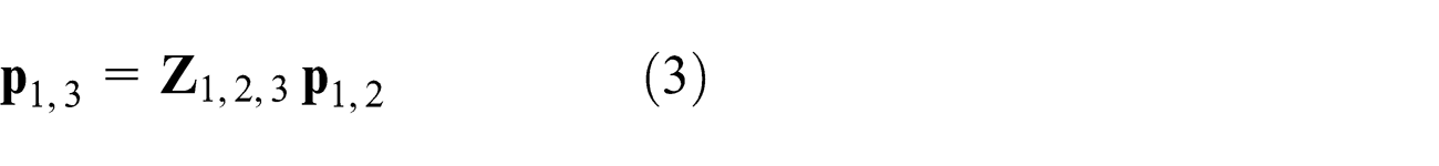
First, according to the notation of Figure 2, let us compute
with s
1,3 = s
1,2 + s
2,3 − 2d
1,2
d
2,3 cos θ. Now, following a simple geometric constructive process from


Thus
Then

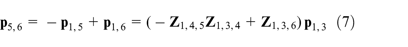
Finally, from


Then

Equation (11) defines the location of point P 8, the foot of a Jansen leg. This equation depends on the set of link dimensions (S); the angle of the input link (θ); the orientation sign of the oriented areas A 1,2,3, A 1,3,4, A 1,3,6, and A 6,5,7; and the location of P 1 and P 2, the centers of the grounded revolute joints. For a given set of values for all these variables, a specific configuration of a Jansen leg is determined, that is, the point P 8 is uniquely defined. We represent a configuration of a Jansen leg as (S, θ, η, P 1, P 2) where η = 0, ..., 15 specifies the combination of signs for the areas A 1,2,3, A 1,3,4, A 1,3,6, and A 6,5,7. Thus, for example, η = 10 = (1010)2 ≡ +− + − implies that A 1,2,3 > 0, A 1,3,4 < 0, A 1,3,6 > 0, and A 6,5,7 < 0.
The ability of bilateration matrices to represent the solution of complex problems in a very compact form can be appreciated when comparing the solution for the position analysis of a Jansen leg presented in Kim et al. 38 with the bilateration-based result of equation (11).
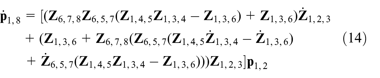
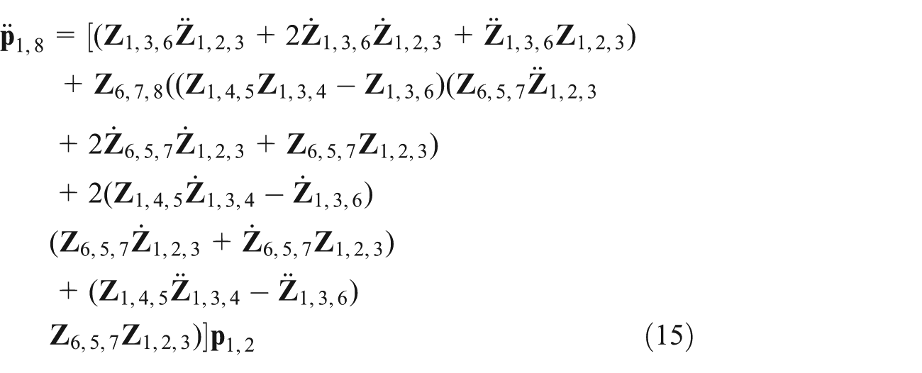
Equations of velocity and acceleration
The velocity and acceleration of the bilateration problem can be readily obtained from the differential and second-order differential with respect to time of equation (1), respectively. That is


The specific expressions for

The bilateration-based equations for the velocity and acceleration of the foot of a Jansen leg can be similarly computed. Then, by properly differentiating equation (11), we have
Beyond the standard Theo Jansen linkage: new gait patterns
Our main aim is to design a novel reconfigurable Theo Jansen linkage that produces a wide variety of gait cycles in order to open new possibilities for innovative applications while maintaining its mechanical simplicity. To this end, those new gait patterns must be based on the topology of a Jansen leg and satisfy at least one of the following goals:
Mimicry of different animal species.
Significant improvements of the locomotion efficiency in non-even surfaces, a range of materials, and external perturbations such as strong winds.
Transform the motion into behaviors beyond locomotion—for example, manipulation skills.
Tracing the coupler curve of a Jansen leg
Figure 4 (top) presents all possible locations of point P 8, computed from equation (11), for sampled values of θ at increments of 1/100 for the case in which s 1,2 = 1073.55, s 1,4 = 553.61, s 1,5 = 631.72, s 1,6 =552.63, s 2,3 = 117.38, s 3,4 = 1216.96, s 3,6 = 1468.58, s 4,5 = 1045.75, s 5,7 = 572.84, s 6,7 = 642.22, s 6,8 = 1292.26, and s 7,8 = 1900.87, with P 1 = (0, 0) T and P 2 = (32.436, 4.632) T . In this procedure, for each value of θ, 16 possible locations for the point P 8 are calculated, one per each combination of signs for the oriented areas A 1,2,3, A 1,3,4, A 1,3,6, and A 6,5,7. This set of link dimensions corresponds to our standard values of a Jansen leg. From Figure 4 (top), a result that contains no information on the connectivity of each sample to its neighbors, we observe that point P 8 shapes to different trajectories. In fact, since a Jansen leg corresponds to a 1-degree-of-freedom pin-jointed planar linkage, any arbitrary point on it generates a plane curve, called coupler curve, when the mechanism moves.

(Top) Possible locations of point P 8, the foot, in all assembly modes of a standard Jansen leg. The lowest sampled curve corresponds to the trajectory used in walking platforms. (Bottom) Traced foot trajectory of a standard Jansen leg. The green path corresponds to the assembly mode family given by A 1,2,3 > 0, A 1,3,4 > 0, A 1,3,6 < 0, and A 6,5,7 < 0. In the red path, A 1,2,3 < 0, A 1,3,4 > 0, A 1,3,6 < 0, and A 6,5,7 < 0.
A novel approach to trace coupler curves, that takes advantage from the geometric information of bilateration-based equations, has been recently discussed in Rojas and Thomas. 37 By tracing, we mean that the connectivity between samples is known. Following such method, for the particular case of a Jansen leg, the curve generated from a known initial feasible configuration (S, θ, η, P 1, P 2) by point P 8—the foot trajectory—can be traced following these steps:
Compute P 8 using equation (11).
Evaluate the oriented areas A 1,2,3, A 1,3,4, A 1,3,6, and A 5,6,7 with the current value of θ. If any of them is equal to zero, the current configuration—that is, the current tuple (S, θ, η, P 1, P 2)—belongs to more than one family of assembly modes (combinations of signs of the oriented areas A 1,2,3, A 1,3,4, A 1,3,6, and A 5,6,7), and the leg movement may evolve along different paths. Identify all these families, that is, determine all feasible values that η can assume.
Increase θ at a specified rate. When θ reaches the limit imposed by the triangular inequalities associated with ΔP 1 P 2 P 3, ΔP 1 P 3 P 4, and ΔP 1 P 3 P 6, start to decrease the variable.
Repeat steps 1–3 for each tuple (S, θ, η,P 1, P 2) until the whole range of θ has been evaluated.
In a standard Jansen leg, the foot trajectory used in walking platforms—the lowest sampled curve in Figure 4 (top)—can be easily traced following the above procedure from any θ between 0 and π with A 1,2,3 > 0, A 1,3,4 > 0, A 1,3,6 < 0, and A 5,6,7 < 0. The corresponding result is depicted in Figure 4 (bottom). It is interesting to note that the standard foot trajectory of a Jansen leg resembles to the plantigrade locomotion of some terrestrial animals. In fact, this trajectory is quite similar to those of the ankles of rats during single-step cycles. 39
Finding the new gait patterns
According to Kuo et al., 40 a linkage can be considered as reconfigurable if during its operation at least one of the following features varies: (a) the effective number of links and/or joints, (b) the kinematic type—that is, the contact constraint—of some joints, (c) the adjacency and incidence of links and joints, and (d) the relative arrangement between joints, or more generally, the relative geometrical relation between joints and links. An interesting consideration for designing reconfigurable mechanisms is that by simply reallocating the joint positions of pin-jointed planar linkages, all types of reconfiguration characteristics, excepting the change of contact constraints in kinematic pairs, may be obtained. 41
In the case of 1-degree-of-freedom pin-jointed planar linkages, it is well known that a change in the link dimensions, that is, a modification in the relative distance between connected joints, a reallocation of joint positions, generates new and different coupler curves. With this basic principle in mind, our approach to obtain novel gait patterns of a Jansen leg is to identify whether by performing small variations in the lengths of the links, interesting foot trajectories can be obtained. To this end, a simple exploratory design study is suggested: vary the standard dimensions of the links in ±20%, first link by link, later in couples, and finally in trios, and register the resulting coupler curves—computed using the discussed procedure—to detect useful gait cycles for future innovative applications in robotics. Following the proposed scheme, we present here five gait patterns that extend the capabilities of the original Jansen leg, generated through minimal changes of link dimensions. Next, each of them is described.
Digitigrade locomotion (cat walking)
The standard foot trajectory of a Jansen leg corresponds to a kind of plantigrade locomotion. A plantigrade is an animal that stands or walks with its podials, such as humans regularly do—an experimental analysis and characterization of the human straight walking can be found in Li and Ceccarelli. 42 In contrast, digitigrades walk on their digits or toes. Example of these kind of animals include dogs, cats, many other mammals, and most birds. Since in each step of digitigrades less foot is touching the surface, these animals present less friction and waste of energy than plantigrades. In consequence, digitigrades tend to be very fast runners. 43 This fact makes digitigrade locomotion of great interest for the development of walking platforms.
Table 1 depicts the foot trajectory of a Jansen leg when the length of the binary link connecting the revolute joint centers P 5 and P 7 is increased by 20% with respect to its standard value in first row, column “Single link.” The shape of this curve is quite similar to the gait cycle of a cat (see Figure 2 in Lacquaniti et al. 44 ). This result is relevant because it shows that by modifying the link dimensions of a standard Jansen leg, that is, by reconfiguring a 1-degree-of-freedom mechanism, we can switch from a plantigrade locomotion to a digitigrade locomotion. Columns “couple of links” and “trio of links” in the first row of Table 1 present other modifications in the link dimensions that further yield digitigrade behaviors. The foot trajectories of the combinations with the ⋆ symbols in the columns are depicted. In each of these figures, the gait of the standard Jansen leg is presented for reference as a black curve. These conventions apply in all next cases.
Identified foot trajectory patterns of interest for reconfigurable walking platforms.

Obstacle avoidance
The height of the foot trajectory of a standard Jansen leg is 9.38 units (Figure 4), that is, a 16.26% of the total height of the leg, a value computed from the grounded revolute joint center P 1 = (0, 0) T to the lowest point of the foot trajectory. Therefore, a walking platform based on standard Jansen legs cannot in principle overpass obstacles higher than this limit (>9.38 units). This is an important drawback because although a Jansen-based system is highly efficient, its operability in rough terrain is reduced.
Second row, column “Single link,” of Table 1 shows the foot trajectory of a Jansen leg when the side length associated with points P 7 and P 8 of the coupler link ΔP 6 P 7 P 8 is decreased by 20% with respect to its standard value. In this case, the height of the foot trajectory is 21.91 units, that is, a 36.74% of the total height of the leg. This new height is more than twice the foot trajectory of a standard Jansen leg. This reconfigurability characteristic could be of interest for applications in uneven terrains—think, for instance, in a team of walking platforms for space exploration missions, that is, exploration of asteroids, comets, planets, and so on. Similar obstacle avoidance patterns can be obtained by simultaneously changing different link lengths of a Jansen leg. These results are presented in the second row, columns “Couple of links” and “Trio of links,” of Table 1.
Jam avoidance (walking on mud)
In soft terrains, walkers can easily get stuck because of the soil conditions. To overcome such situations, a change in the walker’s gait cycle has to be introduced, a versatility that a walking platform based on standard Jansen legs does not offer in its current form. For example, in a transition from a dry soil to a semi-wet mud terrain, the typical foot trajectory of a Jansen leg seems inadequate because of the rigidity variation of the soil in the two scenarios. A gait with the potential to solve this issue is depicted in the third row, column “single link,” of Table 1. Such curve is obtained by increasing 20% the distance between the grounded revolute joint centers P 1 and P 2. Beyond its height, this type of trajectory is of interest because facing the soil with an arc shape, while maintaining a step length close to the original one, allows to extract material and look for a suitable support point at the same time. As in the other reconfigurability characteristics previously discussed, similar jam avoidance patterns can be obtained by simultaneously changing different link lengths of a Jansen leg. The corresponding combinations of link dimensions are presented in the third row, columns “Couple of links” and “Trio of links” of Table 1.
Step climbing
Fourth row of Table 1 presents the modifications in the link dimensions of a standard Jansen leg that yield foot trajectories for climbing steps. This curve results from increasing 16% the distance between the grounded revolute joint centers P 3 and P 6. These gamma-like patterns are more appropriate for climbing steps than the normal foot trajectory due to the significantly shorter contact line with the floor—think, for example, the length of the steps.
Drilling motion
In kinematics of mechanisms, reciprocating motion is in general defined as a recurrent up-and-down or back-and-forth movement. It is normally associated with a repetitive straight-line motion resulting from or giving rise to a full rotation. In complex 1-degree-of-freedom planar linkages, that is, mechanisms with coupler curves of order much higher than six, the degree of a four-bar linkage coupler curve, such standard concept should be extended because overlapping motions different to a straight line can be obtained in specific ranges of the input joint. An example of this kind of reciprocating motion in a double butterfly linkage, a mechanism whose coupler curves can reach order 48, is presented in Rojas and Thomas. 45 Observe that this behavior also occurs in a standard Jansen leg as it can be verified in the sampled curves presented in Figure 4 (top).
Fifth row of Table 1 presents the modifications in the link dimensions of a standard Jansen leg that yield foot trajectories with reciprocating characteristics. These curves, product of increasing 20% the distance between the joint center P 7 and the foot point P 8 for the case of single-link modification, are of interest because their needle-like shapes can be used for drilling activities. With this resulting reconfigurability characteristic, we go one step further because it shows that by varying the link dimensions of a standard Jansen leg, we can, in addition to modify the gait patterns of the walking platform, change the behavior of the system. In this case, from a walker to a driller.
Characterization of leg transformation
We have shown so far that by changing the link dimensions of a standard Jansen leg, a variety of gait patterns of interest for innovative applications in robotics can be identified, that is, digitigrade locomotion, obstacle avoidance, jam avoidance, step climbing, and drilling motion. An important design challenge is how to perform a proper transformation between gait patterns. By proper we mean, for example, that undesired floor contacts must be avoided during the transformation process. Note that the answer to this question has implications in the control and design of the proposed Jansen leg with variable link dimensions.
Following the above discussion, we have devised a simple procedure for transforming a reconfigurable Jansen leg from a pattern A to a pattern B, where both A and B are different and belong to the set of patterns (plantigrade locomotion, digitigrade locomotion, obstacle avoidance, jam avoidance, step climbing, and drilling motion) as described in Section “Beyond the standard Theo Jansen linkage: new gait patterns.” As a proof of concept, we consider the transformation from digitigrade locomotion (d 5,7: +20%) to step climbing (d 3,6: +16%). The proposed method is as follows:
For pattern A, from the current location of the grounded revolute joint centers P
1 and P
2, determine the lowest value of
Repeat Step 1 for pattern B. In our example, θB = 1.27 rad (Figure 5 (right top)).
Define the transformation time values. The transformation starts at time t = to and finalizes at time t = tf . Transformation time Δt = tf − to . For the case study, Δt = 2 with to = 1 and tf = 3 (Figure 5 (right bottom)).
From patterns A and B, determine the link dimensions that have to be changed from a lo value at time t = to (pattern A) to a lf value at time t = tf (pattern B). That is, in the case of our example

Start the transformation, t = to . Set the input angle θ = θA and determine the current location of the foot, say P 8c , from the values computed in Step 1.
For each of the link dimensions determined in Step 4, compute
From the fixed link dimensions, the corresponding lc values of the variable links, the input angle θc , and the current locations of the grounded revolute joint centers P 1 and P 2, compute the new foot location, say P 8n , using equation (11).
Compute the offset
Update the vertical position of the grounded revolute joint centers P
1 and P
2 by subtracting Δy from both ordinates. For the case study, the evolution of
Increase time t at a specified rate δt, that is, t = t + δt. In our example,
Repeat steps 6–9 until t = tf .
This procedure is summarized in the flowchart presented in Figure 6. Figure 5 (left) shows some steps of a simulation of the leg transformation from digitigrade locomotion (d 5,7: +20%) to step climbing (d 3,6: +16%). The binary links of variable dimension and the vertical movement of the grounded revolute joint centers are highlighted in cyan and light green.

Transformation from digitigrade locomotion (d
5,7: +20%) to step climbing (d
3,6: +16%). (Left) Some steps of a simulation of the leg transformation, the binary links of variable dimension, and the vertical movement of the grounded revolute joint centers are highlighted in cyan and light green. The corresponding foot trajectories are also depicted—digitigrade locomotion in black and step climbing in blue. (Right top) The lowest values of

Flowchart of the proposed method for leg transformation (see text for details).
Implementation of a reconfigurable Jansen leg
Figure 7 (center) presents the complete CAD design of a fully functional reconfigurable Jansen leg with four actuators suitable for the transformation procedure discussed in section “Characterization of leg transformation.” In this design, we consider transformations of patterns by changing the lengths of single links, that is, link combinations presented in column “single link” of Table 1. Note that for such transformations, only four length variables are needed, namely, d 1,2, d 3,6, d 5,7, and d 7,8. In this design, the extendable links, which can be modeled as a revolute–prismatic–revolute kinematic chain with an actuated slider joint, correspond to linear actuators utilizing ball screw with two hinge holes at its ends. The base link is designed to allow the up and down movement of the reconfigurable Jansen leg as required by the transformation procedure. Next, such conceptions are detailed.
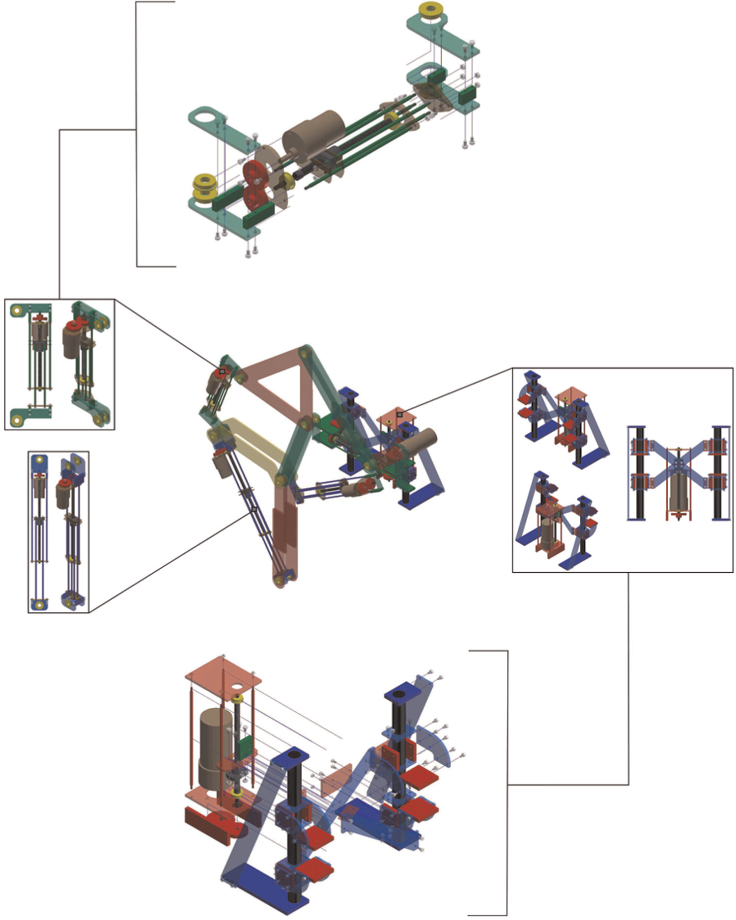
A fully functional reconfigurable Jansen leg with four linear actuators suitable for the transformation procedure presented in section “Characterization of leg transformation” (link combinations presented in column “single link” of Table 1) (center). Zoomed areas present the base system (center right) and links of variable dimension—extendable links (center left). Details of these designs can be observed in the corresponding exploded views—base system (bottom) and extendable links (top).
Extendable links
From Table 1, it is known that the binary links associated with the length variables d 1,2, d 3,6, d 5,7, and d 7,8 have to be changed from standard size (0%) to −20%, +16%, and +20% for obtaining the multiple gait patterns: plantigrade locomotion, digitigrade locomotion, obstacle avoidance, jam avoidance, step climbing, and drilling motion. The linear actuator for these extendable links can be designed to uniquely satisfy these specific requirements, that is, a linear actuator with a discrete number of positions, but, thinking in future works where other modifications may be necessary, a solution with a continuous set of positions is preferred. Moreover, the proposed design should be able to change the link dimension without run off the edge where the two revolute joint centers are located (the hinge holes) because it might generate undesirable contacts between other links in the linkage as it could happen if, for example, the module for reconfiguration by reallocation of joint positions in pin-jointed planar linkages suggested in Rojas et al. 41 is used.
Details of the extendable links designed to satisfy the described conditions can be observed in the exploded view presented in Figure 7 (top). The proposed design is based on a ball screw with a motor properly installed in parallel utilizing gears. Since ball screws tend to back drive because of their low friction, for simplicity, we opted to use motors of high torque and low speed instead of implementing a brake in the system in order to hold the link dimensions. A prototype of this design using a direct current (DC) motor (SPG30E-300K, rated torque: 1176 N mm, rated speed: 12 r/min) and aluminum is shown in Figure 8 (left). It can be verified through simulation that the highest back-drive torques—that is, torque required to support a load in position in a screw—during locomotion are lower than 15.92 N mm (
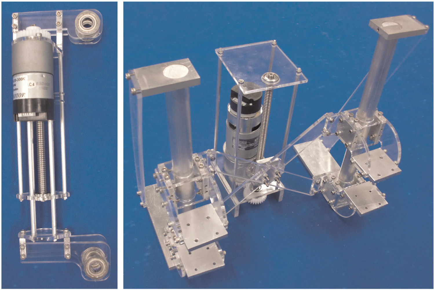
Prototypes of the base system (right) and extendable links (left).
Base system
In order to realize the transformation process without floor contacts as discussed in section “Characterization of leg transformation,” the reconfigurable Jansen leg has to be moved up and down. The easiest way to solve this is to install a linear actuator in the base link, taking into account that such base system must support the moment of the whole mechanism. Observe that if the moment is applied directly to the linear actuator, its motion could be affected and, in the worst case, the system could break. To avoid this, two straight guides are designed to support the base link and its up-and-down movement. The base link and in consequence the reconfigurable Jansen leg are fixed to the guides by four points, two in each guide, which are connected to the linear actuator.
Details of the base system design can be observed in the exploded view presented in Figure 7 (bottom). A prototype of this design is shown in Figure 8, in which a DC motor (RG50M775245000-120K, rated torque: 4.9 N m, rated speed: 30 r/min) was installed for driving the reconfigurable linkage. Since it has been shown that a torque of 1 N m is necessary to drive the Jansen leg at a constant speed; 46 the selected motor has a safety factor of 4.9, a value high enough to resist variations in the torque requirement resulting from, for instance, errors in the parameters.
The base system and extendable links are the principal components of the proposed design of a reconfigurable Jansen leg. Figure 1 presents a working prototype of this mechanism. This implementation uses acrylic for the links of fixed dimension and has been carried out in the SUTD Fabrication Lab using a minimum amount of off-the-shelf parts. In the next section, some results obtained with this prototype are discussed.
Performance
Effectiveness of the design and prototype of the reconfigurable Jansen leg presented in section “Implementation of a reconfigurable Jansen leg,” for generating the multiple gait patterns—section “Beyond the standard Theo Jansen linkage: new gait patterns”—as well as the proposed transformation process—section “Characterization of leg transformation”—was verified through experimentation. In the experiments, the linear actuators of the reconfigurable Jansen leg were driven at constant speed by proportional–integral–derivative (PID) controllers (gains: P = 50, I = 0.008, and D = 0.01), ideal trajectories were generated using the procedure of Figure 6. The resulting leg trajectories were obtained using image processing tools. For measuring the rotation angle of each motor, rotary encoders, utilizing hole sensors, were installed and “Arduino MEGA 2560” was used as control CPU. The obtained experimental results are discussed next.
Generation of gait patterns
The first experiment consisted in comparing the simulated and experimental leg trajectories for the different gait patterns. To this end, the link dimensions of the reconfigurable Jansen leg were set according to the link combinations presented in column “single link” of Table 1 for then actuating the input joint (motor) for 10 cycles. The results of this process are shown in Figure 9 for the gait patterns plantigrade locomotion (standard trajectory of a Jansen leg), digitigrade locomotion, obstacle avoidance, step climbing, and drilling motion. After experimentation, it was discovered that the jam avoidance pattern cannot be generated with the current prototype because when the angle between the input link (corresponding to the line segment

Comparison between the simulated leg trajectory (in gray) and the average experimental trajectory (in red) obtained after 10 cycles of the input joint (curves depicted in black) for the gait patterns plantigrade locomotion (standard trajectory of a Jansen leg), digitigrade locomotion, obstacle avoidance, step climbing, and drilling motion.
Table 2 shows the error and percent error of comparing the width and height of the average experimental trajectory with those of the simulated trajectory, for each of the gait patterns presented in Figure 9. A percent error of less than 22% is obtained for all cases but the step climbing pattern. The origin of such errors is principally due to the non-conformity of link lengths and the presence of joint clearances in the prototype. Both error sources are almost inherent to the fabrication of mechanical designs and are the typical elements that affect the performance of linkages and mechanisms. 47 The big error in the step climbing pattern, 40.01% in height, is given by the greater moment generated by the mechanism. It can be easily shown by simulation that the farthest center of mass point, with respect to the base link, is achieved in such pattern, as a consequence, the joint clearance (backlash effect) affects more this pattern than the others. Table 2 also presents the standard deviation of the experimental leg trajectories for each of the evaluated patterns; in all cases, these values are small, showing the good repeatability of the developed prototype.
Numerical analysis of experiment results.

The above experimental validation is completed by the results presented in Figure 10, in which a comparison between the simulated speed at the foot point, magnitude of the velocity vector of equation (14), and the average experimental speed, computed from the average experimental trajectory (Figure 9), is presented for the gait patterns plantigrade locomotion, digitigrade locomotion, obstacle avoidance, step climbing, and drilling motion. For all these cases, the obtained results and corresponding mean-squared errors prove the adequate generation of gait patterns of the reconfigurable Jansen leg prototype.

Comparison between the simulated speed at the foot point (in black)—that is, magnitude (Euclidean norm) of equation (14)—and the average experimental speed (in red) computed from the average experimental trajectory (Figure 9) for the gait patterns plantigrade locomotion (standard trajectory of a Jansen leg), digitigrade locomotion, obstacle avoidance, step climbing, and drilling motion.
Leg transformation
The second experiment consisted in verifying the transformation process presented in Section “Characterization of leg transformation.” To this end, the transformation from plantigrade locomotion to step climbing was tested. In this experiment, the start time of transformation was set to to = 3.0 s with a transformation time of Δt = 180 s. Figure 11 shows some snapshots of the experiment, highlighting the corresponding leg trajectories during the process. The results verify that the transformation is carried out without undesired floor contacts.
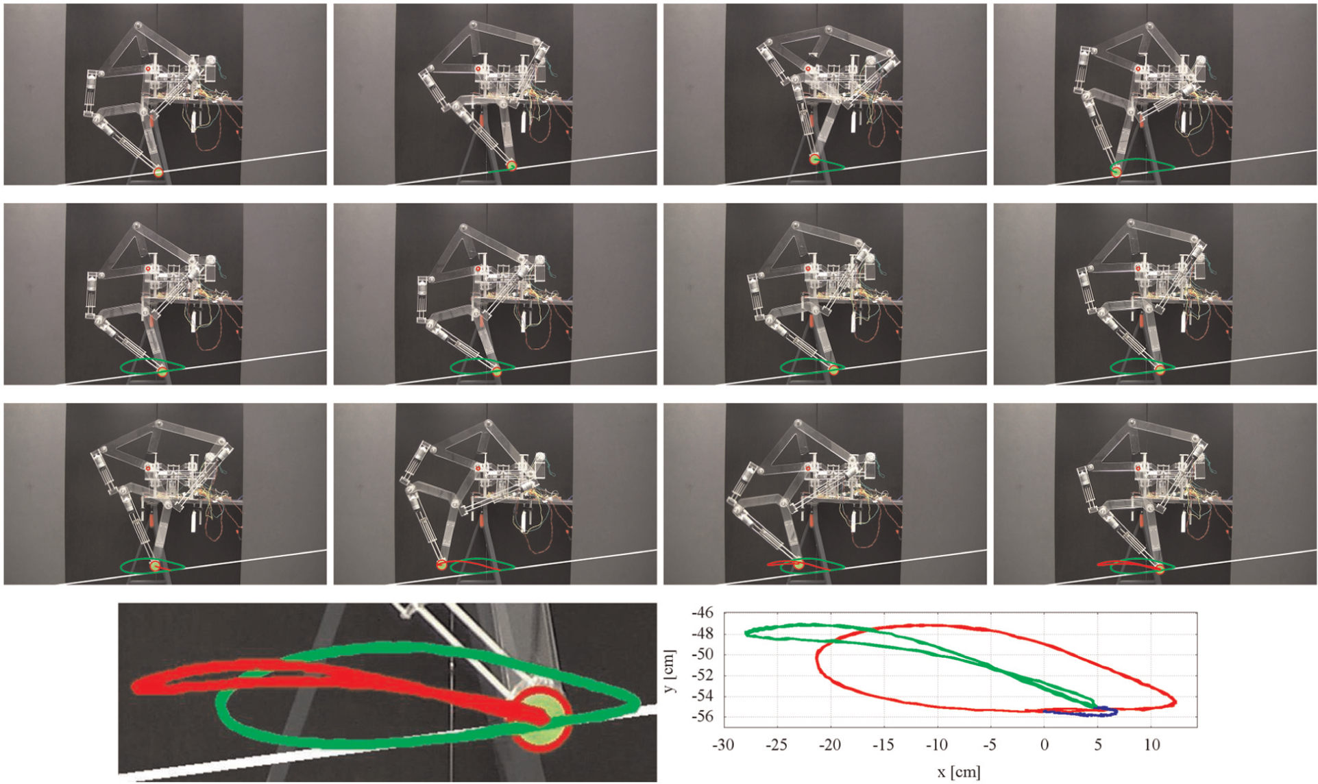
Experimental transformation process from plantigrade locomotion to step climbing (d 5,7: +20%). (Top) Snapshots of the experiment. A green marker, circled by a red line, located at the foot point is tracked. The green and red trajectories represent the plantigrade locomotion pattern and the step climbing pattern, respectively. The white line represents an estimated ground; it is computed because the prototype is tilted due to an inclination in the base system. The small red circle represents the origin of the reference frame. (Bottom left) Zoomed view of the tracked trajectories. (Bottom right) Rotated experimental leg trajectories in which the ground line is parallel to the x axis of the reference frame. The resulting curve during the transformation process is shown in blue.
Conclusion
Since 1-degree-of-freedom planar leg mechanisms are controlled using a single rotary actuator, legged robots based on these linkages are energy efficient with simple gait control. However, the locomotion capabilities of these robots are limited because their legs are constrained to follow a unique gait pattern. With the purpose to overcome this problem, in this article, we have introduced an original design approach to achieve adaptive gait patterns in legged robots for which 1-degree-of-freedom closed kinematic chains form the core. In particular, we have modified a Theo Jansen linkage, a 1-degree-of-freedom leg mechanism widely adopted in walking platforms, to produce a wide variety of gait cycles using the reconfiguration principle of variable allocation of joint positions. In the proposed design, during the reconfiguration process, the system switches from the pin-jointed topology of the standard Jansen linkage (a Grübler kinematic chain) to a 5-degree-of-freedom mechanism with four slider joints.
We have discussed novel approaches to address the position analysis problem and to characterize leg transformation in this reconfigurable design. Five gait patterns of interest, namely, digitigrade locomotion, obstacle avoidance, jam avoidance, step climbing, and drilling motion, have been identified, analyzed, and discussed in relation to potential future applications. These exemplary gait variations considerably extend the capabilities of the original design not only to produce novel gait patterns but also to realize behaviors beyond locomotion. In the proposed reconfigurable Jansen leg, the linear actuators added to the system have to be only controlled during the transformation operation between gait patterns, thus maintaining the mechanical simplicity of the original design during normal operation. A fully functional design of a reconfigurable Jansen leg has been presented and experimental results with a working prototype have been reported.
A four-legged robot is currently being assembled with reconfigurable Jansen legs based on the design herein discussed. The objective with this robot is to test different reconfiguration scenarios and control strategies for limb specialization and graceful degradation. Our long-term aim is to develop systematic methods to design reconfigurable robots capable of transforming in response to needs associated with environment, task, or failures.
Footnotes
Acknowledgements
The authors gratefully acknowledge the assistance of Choo Poh Jim, Sunardi Tay, Raymond Yeong, and Takuya Sasai in the prototyping and experimentation of the reconfigurable Jansen leg reported in this work. This article was presented in part at the 2013 IEEE/RSJ International Conference on Intelligent Robots and Systems, Tokyo, Japan, November 3–7 2013.
Academic Editor: Yan Jin
Declaration of conflicting interests
The authors declare that there is no conflict of interest.
Funding
This research was supported by the SUTD-MIT International Design Center under grants IDG31200110 and IDD41200105 and by the SUTD-ZJU Research Center.