
Abstract
This article proposes a new structure of contact system to improve short-time withstand capacity of direct current circuit breaker. With this new contact system, the electrodynamic repulsion force is compensated. The principle of compensation is illustrated at the beginning. Then the electrodynamic force of the contact system is quantified by analyzing the Lorentz force in conductive loop and the Holm force between contacts. The factors and their influences on electrodynamic force are also investigated. Subsequently, based on multibody dynamics, the movement characteristic model is established. The opening and closing characteristics of breaker and the dynamic stress distribution of closing putters are investigated. The results are verified by experiments. It is indicated that this contact system can improve the short-time withstand capacity. The research could provide theoretical references to large-capacity medium-voltage air direct current circuit breaker development.
Keywords
Introduction
The medium-voltage direct current circuit breaker (DCCB), which plays a critical role in protecting power equipment, creates an increasing demand as it has been widely used in direct current (DC) power system of railways and vessels. 1 Air DCCB is generally adopted in medium-voltage power systems due to its simple principles and reliability. However, with the increasing requirement of system capacity and reliability, short-time withstand capacity and interrupting performance need to be improved.2–5 As one of the critical components of DCCB, the contact system is closely related to breaker’s performances. Short-circuit current would generate electrodynamic repulsion force. And the contacts should avoid being separated by this force for a certain period of time. 6 It is hard for existing medium-voltage DCCB to improve short-time withstand capacity as there is a lack of an effective compensation to the electrodynamic force. Furthermore, the mechanical movement characteristic significantly influences the interrupting performance. On one hand, the opening speed affects arc transferring process. On the other hand, excessive contact bounce increases the possibility of back commutations and repeated breakdowns when interrupting fault currents. Closing putters will be subjected to large impact force during closing process, thus an improper design of closing putter could decrease the mechanism’s operating endurance, which has a negative influence on the breaker’s performance.
This article proposes a new structure of contact system with which the electrodynamic repulsion force is compensated. Structure and function characteristics of this contact system are analyzed first. It is followed by a research on electrical force and movement characteristic. Finite element analysis 7 is used to analyze the influence of current, shaft position, and moving contact bar size on electrical force. Based on multibody dynamics,8,9 the dynamic characteristic of the circuit breaker has been simulated. Then the opening and closing characteristics of moving contact are obtained. Moreover, impacts of spring coefficients on opening characteristics and stress distribution of closing putter during closing process are all analyzed. Based on the results, the optimized design scheme of DC circuit breaker is put forward.
The existing contact system structure of medium-voltage air DCCB is demonstrated in Figure 1. It mainly includes upper and lower bus bars, moving contact rod, moving and fixed contacts, contact spring and opening spring, closing putter, and flexible copper wire. In this contact system, the contact pressure is provided by contact spring and closing putter. The only way to improve short-time withstand capacity is to increase the contact pressure, namely, to increase the output of contact spring and operating mechanism. This method increases the unreliability of circuit breaker, decreases the mechanical operating endurance, and requires better closing putter material intensity. This will lead to more problems for design. It is hard to improve short-time withstand capacity with the existing contact systems, so the performance of circuit breaker is restricted. The research on the contact system is essential to improve the performance of circuit breakers.
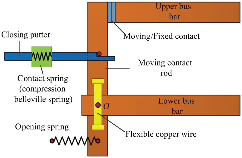
Existing contact system structure of a medium-voltage air DCCB.
Structure of electrodynamic repulsion force compensated contact system
To improve the short-time withstand capacity, this article proposes a new contact system with electrodynamic repulsion force compensation based on a flexible shaft. The short-time withstand current increases as the electrodynamic force being compensated by Lorentz force on moving contact rod and flexible copper wire. Its structure and working principle are presented in Figure 2. As shown in Figure 2(a), the main shaft is fixed on the holder by a cylindrical pin inserted through the obround hole O2. The operating mechanism drives the closing process by a closing putter. The opening spring Sp and contact spring Sc drive the opening process. Force analysis is illustrated in Figure 2(b) where Fm is the closing push force, Fh is the Holm force, fL is the Lorentz force, Fsp is the opening spring force, Fsc is the contact spring force, and Fg is the arc aerodynamic force.

(a) Structure and (b) working principle of the new contact system.
In closing state, O1 is fixed and O2 is in the middle of the obround hole. Therefore, the rotation axis of moving contact rod is at O1. The opening spring Sp does not affect the rotation, while the torque generated by the contact spring force Fsc provides the contact pressure. As the Lorentz force of moving contact rod is distributed over the whole rod, the Lorentz torque on either side of the O1 shaft will be partially offset eliminated. The reduction in repulsion will significantly improve the short-time withstand capacity.
At the opening moment, the closing putter is separated from the moving contact rod by the operation of release. Thus, O1 and O2 are not fixed in the horizontal direction. Spring forces on the moving contact rod Fsp and Fsc and electrodynamic forces Fh and fL will provide a left acceleration while opening. Consequently, the moving contact rod will open at a high speed.
After a short period of speed acceleration and translation, obround hole position at O1 will be limited by the pin. The movement will change into rotation around O2. The moving contact rod will complete the opening process with the spring forces Fsp and Fsc.
Electrodynamic repulsion force analysis
Calculating method of electrodynamic repulsion force
The repulsion force of the contact system includes Lorentz force and Holm force. The Lorentz force of contact rod is calculated according to Ampere’s law. For a rotational contact system structure, the first step should be the resultant moment calculating Lorentz force on moving contact rod toward the shaft by equation (1) 10

Then the resultant Lorentz force
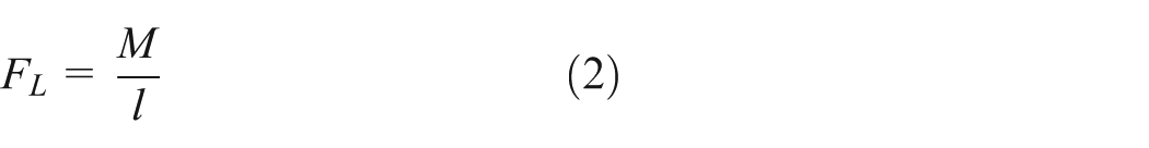
where l (m) is the distance from the contact center to the moving contact shaft.
According to the electrical contact theory, 11 the expression of Holm force FH is

where I (A) is the current flowing through the contact system, ξ (0.6 is adopted) is the contact coefficient, H (kgf mm−2) is the Brinell hardness of contact material, A (mm2) is the apparent contacting space, and FN (N) is the practical contact pressure. FN is the difference between the terminal contact pressure Fk and the electrodynamic repulsion force, which can be expressed as

Then the expression of Holm force FH is

In Figure 2(b), when moving contact is in closing state, the moving contact rod is fixed, so the horizontal resultant force on moving contact rod is balanced. Thus, the force provided by closing putter is

Current density and magnetic field distribution are solved by finite element method. Simplification is adopted to reduce computational complexity. The model applied in calculation is shown in Figure 3. It only includes upper and lower bus bars, moving and fixed contacts, moving contact rod, and flexible copper wire.

Calculation model of contact system.
Influencing factors of electrodynamic repulsion force
Influence of current
The moment of Lorentz force on moving contact rod under different current values is calculated to obtain the resultant Lorentz force (Figure 4). After that, the Holm force of contacts and the minimum terminal pressure keeping the contacts closed could be solved by equations (5) and (6).
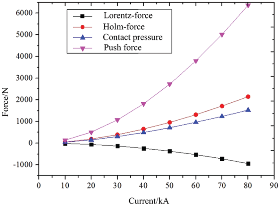
Relationship between the electrodynamic force, push force, and current.
It is obvious that the Lorentz force is in a state of over-compensating, which means the resultant force is transformed into contact pressure. This effective compensation can significantly reduce the required spring force. With 50 kA current, the contact pressure generated by Lorentz force can reach up to 368 N and the Holm force is 956 N. To ensure the contacts will not be separated, the minimum pre-pressure provided by contact spring is 713 N according to this calculation.
If the shaft is at O2, the compensation of moving contact rod and flexible copper wire will not exist. With 50 kA current, the Lorentz force can reach up to 463 N and the Holm force of contacts is 956 N. The minimum contact pre-pressure to be provided should be 1420 N. To be compared, the compensation force reduces 50% of pre-pressure provided (707 N). Therefore, this new contact structure with flexible shaft has better short-time withstand capacity.
Influence of shaft position
The Lorentz force is distributed in the whole moving contact rod, so the shaft position of the rod O1 has a strong influence on the compensation force. The relationship between Lorentz force, Holm force, contact pre-pressure, push force, and shaft position O1 with 50 kA current is demonstrated in Figure 5. Position 0 is the initiate shaft position, where negative value means downward shift and positive value means upward shift.

Relationship between the electrodynamic force, push force, and shaft position.
The result proves the strong influence of the shaft position on Lorentz force compensation. When O1 shifts up, the compensation of Lorentz force increases. Moreover, the contact spring arm becomes longer with O1 shifting up, and the required spring force decreases correspondingly. It can be observed from equation 5 that the required closing push force also decreases significantly. It indicates that upward shift of O1 is an effective method to improve short-time withstand capacity of circuit breakers. However, the upward shift of O1 could also reduce the distance between the closing putter and upper bus bar. So a certain insulation distance should be kept to maintain the breaking characteristics of circuit breakers.
Movement characteristic calculation of mechanism
In this part, the movement characteristic of the breaker is calculated by multibody dynamics software ADAMS. 12 The influence of opening spring and contact spring on opening speed is analyzed first. Then the moving contact bounces and the dynamic stress distribution of closing putter during closing process is analyzed.
To analyze the dynamic stress distribution of closing putter during closing process, the putter is subdivided into finite element to generate flexible components. The finite element model is shown in Figure 6. One end of the putter is connected with the closing mechanism and the other end is fixed with putter head by a round hole. Dynamic characteristic is calculated by importing the flexible components to ADAMS.
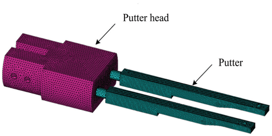
Finite element model of closing putter.
Opening process
The simulated contact opening characteristic curve is shown in Figure 7.

Simulated contact displacement curve during the opening process.
According to the result, the contacts get separated at around 2.5 ms, reach the maximum opening range at 13.7 ms, and the whole opening period lasts for 11.2 ms. When the moving contact reaches the maximum opening range, it collides with the limited block and bounds around 7.3 ms. The first bounding range is 2.2 mm. The opening spring Sp and the contact spring Sc provide the driving force to close, so they have direct influence on opening speed and contact bounce.
Figure 8(a) shows the influence of initial opening spring force on the opening characteristic of the contact system. It is obvious that when the initial opening spring force increased from 400 to 2000 N, the opening period reduces from 14.2 to 6.9 ms. Increasing the initial opening spring force can improve the contact moving speed effectively and reduce the opening period. However, as the initial opening spring force increases, the bounce range and period decrease at first, then increase, and decrease afterward till the end.

Influence of opening spring on the opening characteristic: (a) initial force and (b) stiffness coefficient.
Figure 8(b) shows the influence of opening spring stiffness coefficient on contact opening characteristic. The result indicates that as the opening spring stiffness coefficient increases, the opening period of moving contact is not significantly increased. This is because when the moving contact reaches the maximum opening range, the force of opening spring is limited by large stiffness coefficient, which leads to severe contact bounce.
Figure 9 shows the influence of initial contact spring force and stiffness coefficient on the opening characteristic of the contact system. As the contact spring is close to the shaft, the force arm as well as the influence is limited. With the initial opening spring force increasing and stiffness coefficient decreasing, the opening period just slightly decreases.

Influence of contact spring on the opening characteristic: (a) initial force and (b) stiffness coefficient.
The optimized design schemes of DCCB are put forward according to the simulation results. Then an experiment under unloaded condition is conducted. As illustrated in Figure 10, an angular displacement sensor WDD35 and a high-speed camera are applied in the experiment. The output voltage of WDD35 is linearly related to the change in angular which indicates the change in the main shaft angle. And the movement of moving contact in opening process is recorded by a high-speed camera. Then the opening characteristic curve is obtained.

Experimental schematic diagram.
Figure 11 demonstrates the comparison of simulation and experiment. In the experiment, the speed of moving contact drops near the maximum opening range, and opening period lasts longer. This is because the flexible copper wire would hold back the contact during the opening process. The inhibition enhances as the opening range increases. In simulation, this factor is not considered. Overall, the experimental results and simulation results are in good agreement. The simulation is proved to be efficient.

Experimental verification of the opening characteristic.
Closing process
The closing process is simulated to analyze the contact bounce and putter pressure. Figure 12 shows how the operating mechanism drives the closing process. The arms are connected by pins and shafts Oa, Ob, and Oc are fixed on the holder by bearings. The moving contact is driven closed by the closing putter, which is pushed by the spring acting on the arm.
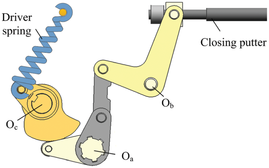
Closing operating mechanism of DCCB.
The contact displacement curve during the closing process is shown in Figure 13. According to the curve, the moving contact moves at around 1.8 ms and reaches the closing position at 26.9 ms. It lasts 25.1 ms for the contact to close. Only a small moving contact bounce with a range of 0.4 mm occurs. The closing putter is locked when moving contact reaches closing position, so the moving contact rod can only rotate around closing putter’s point of action O1 and its rotating range is limited by the obround hole size of moving contact rod axis O2.

Simulation of the contact displacement curve during the closing process.
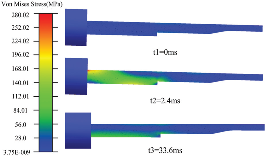
The closing putter is subjected to a strong impact force with the contacts closing. To assist the design, the dynamic stress model is set up and the dynamic stress distribution of closing putter is calculated. The dynamic stress of closing putter at different times during closing process is shown in Figure 14. It can be obtained from the result that before closing (t1 − t2), there is little pressure on the putter. When putter collides with moving contact since t2, the opening range decreases and the putter pushes the moving contact to complete the closing process. When contacts collide, putter stress increases rapidly and reaches the maximum of 330.73 MPa, which focuses on the putter head. When the closing process completes, putter stress decreases at t3, and the stress distribution is more balanced than that of t2.

Dynamic stress.
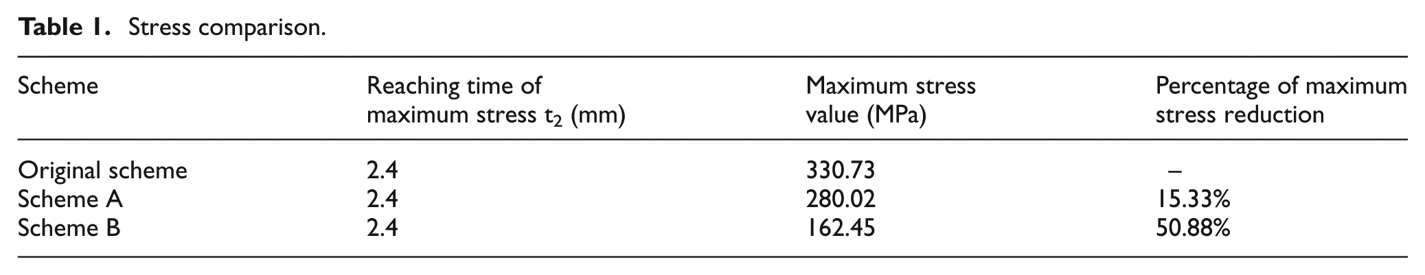
The structure of closing putter is optimized to improve the operating endurance. Figure 15 shows two different optimized schemes. Scheme A used a rectangular plug on the putter head. Scheme B increased 2 mm of putter thickness. The stress distribution is shown in Figures 16 and 17. It can be seen from the comparison in Table 1 that the maximum stress at t2 decreased and the stress distribution becomes more balanced.
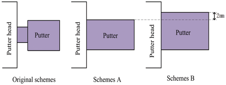
Optimized schemes.
Stress simulation of scheme A.

Stress simulation of scheme B.
Stress comparison.
Conclusion
To improve the short-time withstand capacity of DCCB, a new type of contact system with electrodynamic repulsive force compensation is proposed in this article. By simulation, the main influence factors and their influences on electrodynamic force are obtained. Then the movement characteristic of the contact is calculated by multibody dynamics. And the simulation is verified by experiment. The conclusions are given below.
Based on a flexible shaft, this new type of contact system takes advantage of the Lorentz force of moving contact rod and flexible copper wire to compensate the electrodynamic force of contacts. It improves the short-time withstand capacity and utilization efficiency of the components.
The shaft position significantly influences the Lorentz force on moving contact rod. The upward shift of the shaft can sharply increase the compensating force and reduce the output of the contact spring.
As the initial opening spring force increases, the bounce range and period decrease at first, then increase, and decrease afterward till the end. The opening spring stiffness coefficient has little influence on the opening period of moving contact.
The maximum closing putter stress is 330.73 MPa, which appears at the time of the closing putter colliding with the moving contact rod. The stress is focused on the putter head. Using a rectangular plug on the putter head, the maximum stress reduces 15.33%. By increasing 2 mm of putter thickness, the maximum stress reduced 50.88%.
The opening process experiment verified the accuracy of simulating model. This method to assist DCCB mechanism design is proved to be feasible.
Footnotes
Declaration of conflicting interests
The authors declare that there is no conflict of interest.
Funding
This work was supported by National Key Basic Research Program of China (973 Program) 2015CB251000, the National Natural Science Foundation of China under Grant 51221005 and 51377128, the New Century Excellent Talents program from the Ministry of Education of China, and the Fundamental Research Funds for the Central Universities.