
Abstract
Taking supercapacitor and battery pack as the energy storage unit, a novel type of regenerative braking system for electric vehicle driven by in-wheel motors is presented, and a braking energy regeneration control strategy is set up. Then, a co-simulation test based on CRUISE and Simulink is conducted. The results of simulation show that the novel type of system can ensure the safety of battery pack and significantly improve the rate of energy regeneration.
Introduction
Because of environmental pollution and energy crisis, it is inevitable for the wide application of electric vehicle (EV) to realize sustainable development of the world. 1 The technology of EV driven by in-wheel motors devoid of the traditional mechanical transmission design constraints adopts the flexible cable among power producer and driven motors, which becomes the focus of automotive technology research. 2 In-wheel motor is not a new-born technology; Lohner-Porsche, an old hybrid EV, using four in-wheel motors was presented for the first time at the Universal Exhibition in Paris as early as 1898. 3 In 2006, C-Métisse equipped with an in-wheel motor of TM4 Company was displayed at the Paris Exhibition. 4 A prototype pure-electric ground vehicle and a four-wheel motor series hybrid prototype equipped with four in-wheel motors were studied to show the energy conservation potential for using in-wheel motors.5–7
The short driving distance is a fatal weakness for the development of EV. By recycling braking energy effectively, the driving distance of an EV, driven in the urban areas, could be increased about 26% according to the statistical data. 8 It can be seen that regenerative braking is an effective approach to extend the driving range of an EV. Regenerative braking, as an important working pattern to EV, can recycle and store the braking energy to the storage unit during the vehicle deceleration or braking. In Gao et al., 9 the efficiency of regenerative braking in the case of three different braking conditions was evaluated, and the results indicated that a great amount of braking energy can be recovered. The research on regenerative braking system for a rear-driven electrified minivan was carried out and a new regenerative braking control strategy named “modified control strategy” was proposed. 10 In Zou et al., 11 supercapacitors were employed in the regenerative braking system to recycle high-current braking energy. The experiment results showed that the maximum braking energy regeneration efficiency could reach up to 88%. In Hong et al., 12 Gao and Ehsani, 13 and Panagiotidis et al., 14 the characteristics of regenerative braking were analyzed and the energy recovery efficiency was also calculated.
However, not all of the braking energy can be recycled. The regenerative braking process is impacted by many factors, such as battery state of charge (SOC) and braking intensity. 15 The braking power and the braking current of motors are distributed in a wide range during the process of actual regenerative braking. It is obvious that the overlarge current cannot charge the battery directly. In this article, a new type of regenerative braking system taking battery pack and supercapacitor as energy storage is presented for a higher rate of braking energy recovery in EV driven by in-wheel motors.
The implementation of the regenerative braking system
The configuration of the regenerative braking system is shown in Figure 1; the system comprises in-wheel motors, direct current (DC)/DC controller, battery pack, and supercapacitor. The battery using lithium iron phosphate and the supercapacitor are the energy storage units. In order to recycle more braking energy in the braking process and prevent battery damage from large current, a supercapacitor is added to the system.

Configuration of the regenerative braking system.
The working principle of the novel regenerative braking system is as follows. During braking, the required brake torque is produced by in-wheel motor. The recovery direction of braking energy is controlled by DC/DC controller according to the braking current intensity. If the braking current is less than the charging current threshold, the braking energy is stored in the battery pack directly. Otherwise, the braking energy is stored in the supercapacitor for the sake of recycling more braking energy and preventing battery damage from large current; then, the braking energy is transferred from the supercapacitor into the battery pack in the form of low current under non-braking condition.
The model of regenerative braking system
Supercapacitor model
According to the equivalent circuit diagram shown in Figure 2, the supercapacitor model of the braking energy storage unit is established, which consists of ideal capacitor and equivalent resistor.

The equivalent circuit diagram of supercapacitor.
Using the analysis method of state equation, Figure 2 can be expressed by the following formulas
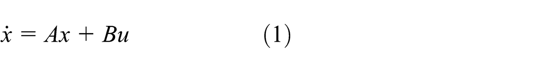
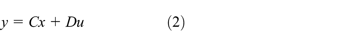
where
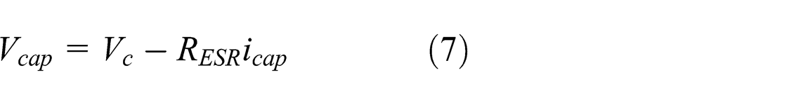
According to the Kirchhoff law and the charging and discharging characteristics of supercapacitor, the terminal voltage of the supercapacitor can be expressed by the following formula if


where
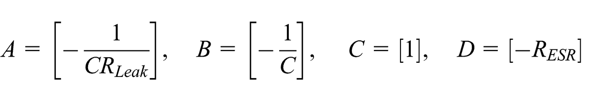
According to formulas (4) and (5), formula (6) can be obtained as follows

The parameters A, B, C, and D shown in formulas (1) and (2) can be expressed as follows based on formulas (5) and (6)
A voltage cut-off value
where
The SOC of the supercapacitor refers to the ratio of energy stored in the supercapacitor corresponding to the terminal voltage

Battery pack model
The battery pack model includes the following calculation modules:
Terminal voltage calculation module of battery
This module is used to calculate the internal resistance and terminal voltage of battery pack. The calculation formulas are as follows


Based on the formulas above, the terminal voltage of battery
2. SOC calculation module of battery
The SOC of the battery can be obtained according to current integration. 18 It is shown in the following formula

where
Control strategy for braking energy recycling
In this article, the control strategy for the braking energy recycling of the regenerative braking system is built up based on logic threshold value control. 19
According to the logic threshold value of braking current, battery SOC and supercapacitor SOC are set in advance; the process of braking energy recycling is divided into three sub-processes: the braking energy is recycled to the battery when the braking current value is less than the logic threshold value of braking current. The energy is recycled to the supercapacitor when the braking current value is greater than the logic threshold value of braking current and the energy is translated from supercapacitor into battery under non-braking condition. The specific control flow diagram is shown in Figure 3. A1, A2, and A3 represent the logic threshold value of the braking current, the logic threshold value of the battery SOC, and the logic threshold value of the supercapacitor SOC, respectively.

The control flow diagram.
Acceleration of vehicle, represented by ‘a’, determines the motion state of the system. The vehicle is run under braking condition when the acceleration a < 0. Taking the maximum allowable charging current of lithium iron phosphate battery as the basis of logic threshold design of braking current not damaging the battery pack, the threshold A1 is set to 50 A. The braking energy is recycled into the supercapacitor when the braking current is larger than A1. In order to improve the energy recovery efficiency and decrease the energy loss in the energy transfer process from supercapacitor to battery pack, first the braking energy should be recycled into battery pack. Thus, the SOC of the lithium iron phosphate battery threshold A2 is set to 0.8. The braking energy is recycled into battery pack if the braking current is less than A2, otherwise it is recycled into the supercapacitor. The braking energy is transferred from the supercapacitor to battery pack when the vehicle is run under non-braking condition. Setting the SOC of supercapacitor to 0.4 according to the impact of supercapacitor charging and discharging characteristics on energy transfer, the braking energy stored in the supercapacitor is transferred to battery pack if the SOC of supercapacitor is larger than A3.
Simulation results and analysis
The vehicle dynamics model driven by in-wheel motors is built up by AVL CRUISE software. In addition, the EV, in this article, is a four-wheel independent drive EV. Therefore, the simulation model of the EV driven by in-wheel motors based on AVL CRUISE is shown in Figure 4.

AVL CRUISE model of electric vehicle driven by in-wheel motors.
AVL CRUISE can provide a precise vehicle system dynamics model and EV components model. Not only the vehicle body model but also battery pack model, driving motor model, tire model, and braking system are included in the simulation model. The MATLAB.dll module used to co-simulate with MATLAB/Simulink is also added in the vehicle dynamics model. The main parameters of the EV, battery pack, and in-wheel motor in the simulation process are shown in Table 1.
Simulation parameters.
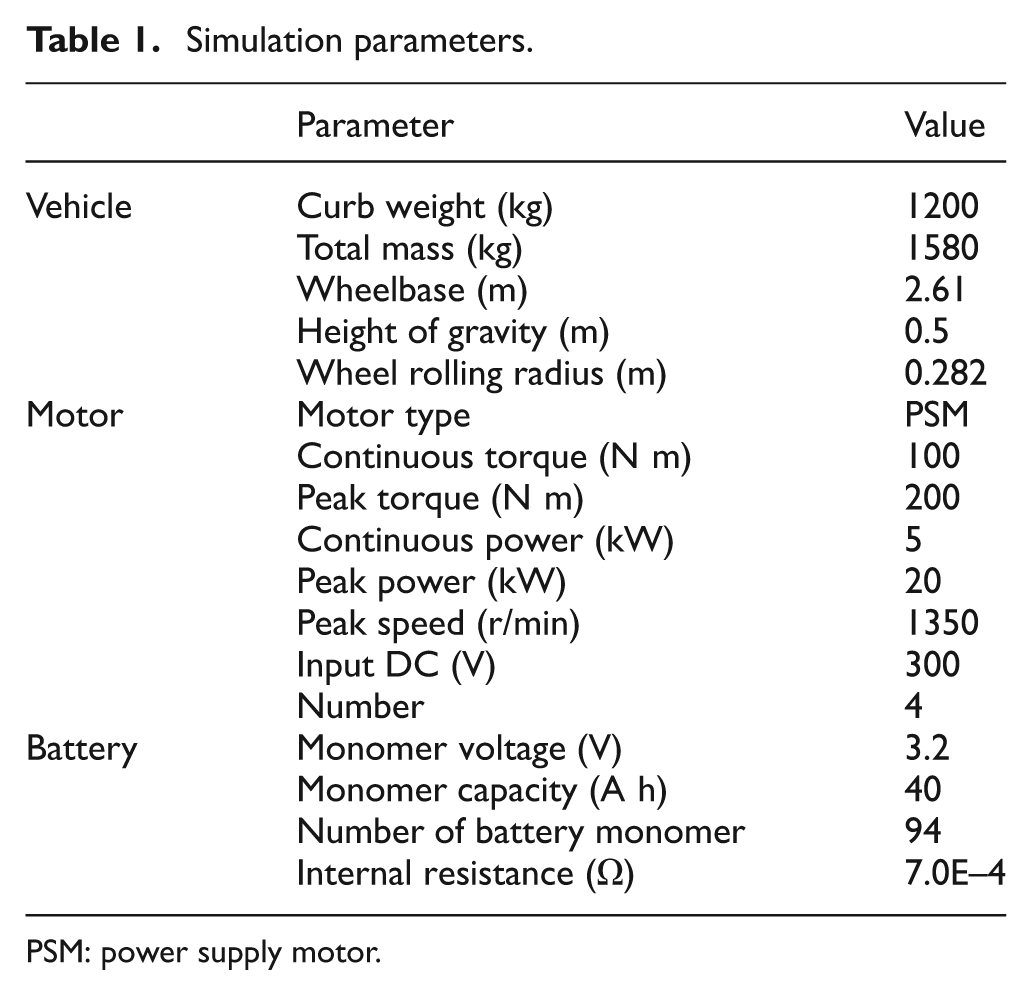
PSM: power supply motor.
The simulation model for the braking energy storage unit of the regenerative braking system is established in MATLAB/Simulink. The top-level module of the supercapacitor model based on the supercapacitor circuit diagram in Figure 2 and formulas (5) and (6) is shown in Figure 5, which consists of supercapacitor SOC calculation module, current calculation module, and temperature calculation module.

Simulation model of supercapacitor.
This model can simulate the supercapacitor and one of the energy storage units, and recycle the large braking energy in the simulation process. Charge and discharge characteristics of it have been verified, and the results showed that the characteristics of the above simulation model met well with the tests of the realistic capacitor. Therefore, the simulation model of the supercapacitor which is established in MATLAB/Simulink can well reflect the actual characteristics of the supercapacitor.
Simulation conditions
Based on the five typical working conditions, namely, low-intensity braking, medium-intensity braking, high-intensity braking, Federal Test Procedure (FTP)-75 circulation condition, and New European Driving Cycle (NEDC) circulation condition, the simulation tests are carried out. The low-, medium-, and high-intensity braking conditions are defined as three driving cycles. Each loop of the low-intensity braking condition includes three processes: the acceleration process from 0 to 40 km/h, the driving process at a constant speed of 40 km/h, and the braking process from 40 km/h to 0. Similarly, each loop of the medium-intensity braking condition also includes three processes: the acceleration process from 0 to 80 km/h, the driving process at a constant speed of 80 km/h, and the braking process from 80 km/h to 0. The loop process of the high-intensity braking condition is as follows: the acceleration process from 0 to 120 km/h, the driving process at a constant speed of 120 km/h, and the braking process from 120 km/h to 0, which is similar to the above conditions.
Simulation and verification
Because of the design targets of improving the energy recovery efficiency and ensuring battery pack safety, battery SOC, and supercapacitor SOC along with vehicle speed, the comparison of the SOC value of battery for the system equipped with supercapacitor and without supercapacitor is regarded as the main evaluation index to evaluate the performance of the novel regenerative braking system.
The simulation results of low-intensity braking, medium-intensity braking, and high-intensity braking conditions are shown in Figures 6–11. The battery current and supercapacitor current along with vehicle speed for vehicle driving on low-intensity braking, medium-intensity braking, and high-intensity braking conditions are shown in Figures 6, 8, and 10. During low-intensity braking, the current of supercapacitor remained 0, except for some instant impulse current. The braking current and supercapacitor current, during medium-intensity braking, have been more than 80 A. The maximum braking current has been more than 300 A during high-intensity braking. However, the current of battery pack is always less than 50 A, within the range of setting threshold, which protects the safety of the battery pack effectively. The battery SOC and supercapacitor SOC along with vehicle speed for vehicle driving on low-intensity braking, medium-intensity braking, and high-intensity braking conditions are shown in Figures 7, 9, and 11. During low-intensity braking, the braking energy is recovered by battery pack completely because of the small braking current so that the SOC of battery pack increases while the value of supercapacitor is almost unchanged. Because the braking current is more than 50 A mostly, the SOC of supercapacitor, during medium-intensity braking, increases obviously. However, the value of battery pack has only a slight increase. Similar to medium-intensity braking, during high-intensity braking simulation, the capacitor SOC shows a great increase and the battery SOC gradually increases. As can also be seen from Figures 7, 9, and 11, the SOC value of supercapacitor decreases, while the value of battery pack increases during non-braking simulation. The above analysis shows that the simulation results can satisfy the control strategy for regenerative braking based on logic threshold.

Battery current and supercapacitor current along with vehicle speed in low-intensity braking cycle.
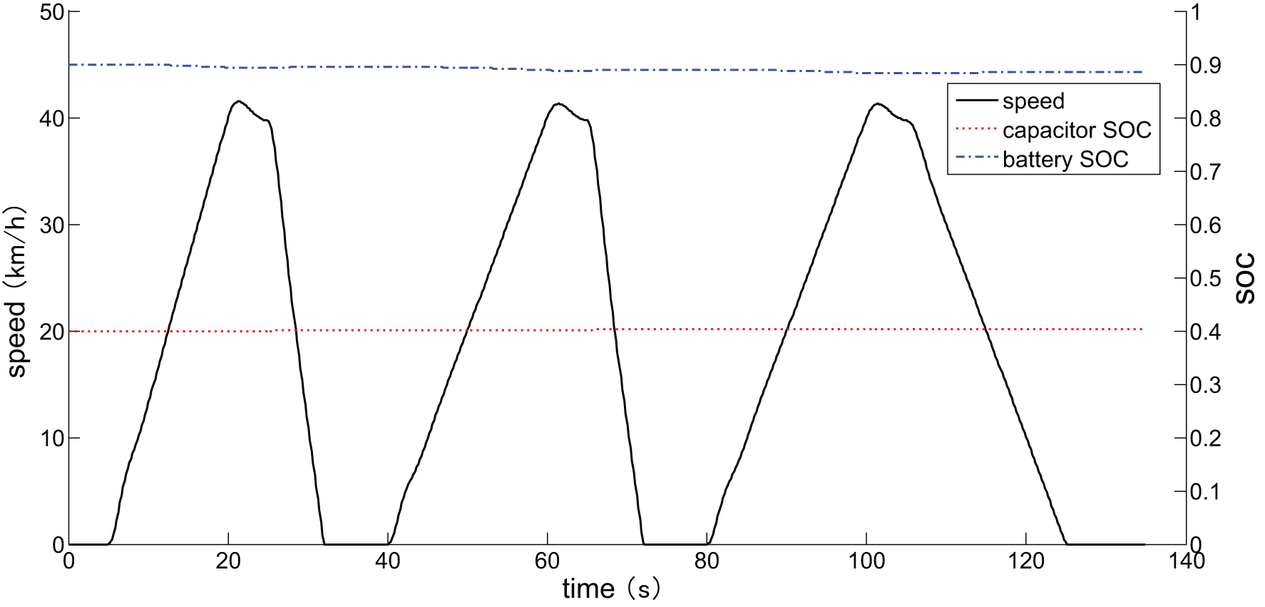
Battery SOC and supercapacitor SOC along with vehicle speed in low-intensity braking cycle.

Battery current and capacitor current along with vehicle speed in medium-intensity braking cycle.

Battery SOC and supercapacitor SOC with vehicle speed in medium-intensity braking cycle.

Battery current and supercapacitor current along with vehicle speed in high-intensity braking cycle.

Battery SOC and supercapacitor SOC along with vehicle speed in high-intensity braking cycle.
Figure 12 shows the comparison of battery SOC for the system equipped with supercapacitor and without supercapacitor during simulation under medium-intensity braking condition. The simulation result shows that the battery SOC has increased slightly when the system is equipped with supercapacitor. We can safely conclude that supercapacitor appears to have played a role in improving the rate of energy regeneration.

Comparison of battery SOC for medium-intensity braking.
Figure 13 shows the comparison of battery SOC for the system equipped with supercapacitor and without supercapacitor during simulation under high-intensity braking condition. Compared with medium-intensity braking condition, the battery SOC has increased obviously when the system is equipped with supercapacitor. Therefore, adding supercapacitor to the energy storing device could significantly improve the rate of energy regeneration.

Comparison of battery SOC for high-intensity braking.
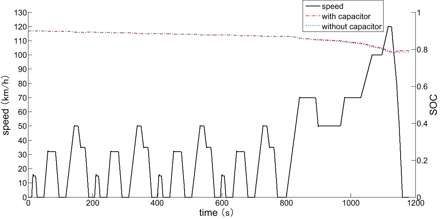
Figure 14 shows battery SOC and the supercapacitor SOC along with vehicle speed for simulation under FTP-75 cycle condition. It can be seen that the SOC of the supercapacitor increases significantly when the vehicle brakes at higher speed, while the SOC of the battery increases gently when the vehicle brakes at lower speed. During non-braking simulation, the supercapacitor SOC decreases while the battery SOC increases slowly.

Battery SOC and supercapacitor SOC along with vehicle speed in FTP-75 cycle.
Figure 15 shows the comparison of battery SOC for the system equipped with supercapacitor and without supercapacitor during simulation in FTP-75 cycle. However, the improvement in battery SOC for the system equipped with supercapacitor compared to the one without supercapacitor is not obvious for less-medium and high-intensity braking conditions of FTP-75 cycle. It can be seen that the supercapacitor has played a part in the process of the braking energy recycling.

Comparison of battery SOC for FTP-75 cycle.
In order to further verify the performance of the novel regenerative braking system, the simulation tests based on NEDC circulation condition were carried out. The simulation results are shown in Figures 16 and 17. Figure 16 shows the battery SOC and the supercapacitor SOC along with vehicle speed for simulation under the NEDC cycle condition. At the beginning of the cycle condition, the braking intensity is small and the braking energy is recovered by battery pack completely because of low vehicle speed. Hence, the SOC of battery pack increases during vehicle braking, while the value of supercapacitor is almost unchanged. However, the SOC of the supercapacitor increases significantly when the vehicle brakes at higher speed. During non-braking simulation, the supercapacitor SOC decreases while the battery SOC increases slowly.

Battery SOC and supercapacitor SOC along with vehicle speed in NEDC cycle.
Comparison of battery SOC for NEDC cycle.
Figure 17 shows the comparison of battery SOC for the system equipped with supercapacitor and without supercapacitor during simulation in NEDC cycle. However, the improvement in battery SOC for the system equipped with supercapacitor compared to the one without supercapacitor is not obvious for less-, medium- and high-intensity braking condition of NEDC cycle. It can be seen that the supercapacitor has played a part in the process of the braking energy recycling.
Discussion
A novel type of regenerative braking system with supercapacitor for EV driven by in-wheel motors that can bear large charging current is presented. The vehicle simulation model with the supercapacitor model and the in-wheel motor driving system is built and a braking energy regeneration control strategy is set up. The co-simulation for vehicle driving on four typical working conditions on the basis of AVL CRUISE and Simulink is carried out. By using supercapacitor and battery pack as energy storage units, the overlarge current can be recovered in the braking process. The results of simulation show that the novel type of system can ensure the safety of battery pack and significantly improve the rate of energy regeneration at the same time. It is evident that the supercapacitor technologies will improve the performances of regenerative braking system for EV driven by in-wheel motors and bring regenerative braking technology in a new level.
Footnotes
Academic Editor: Chun-Liang Yeh
Declaration of conflicting interests
The authors declare that there is no conflict of interests regarding the publication of this article.
Funding
This work was supported by National Science Foundation of China (E50907030) and China Postdoctoral Science Foundation (2013M540248).