
Abstract
A nonlinear modeling of magnetostrictive cantilever beam actuators is proposed by integrating an energy-based constitutive magnetostrictive model with the classical laminated beam theory in this article. The composite stiffness and the magnetic field are identified as the critical parameters which significantly influence the performance of the cantilever beam. Detailed experimental studies are carried out with different applied magnetic fields and various cantilever beam thicknesses. The experimental results verified the nonlinearity of the magnetomechanical response of the structure.
Introduction
Galfenol (iron–gallium alloy) is a type of smart material that has excellent magnetostrictive properties, including high free strain at low magnetic fields, high stress sensitivity, and useful thermo-mechanical properties.1–3 The laminated bender structures utilizing Galfenol drivers provide a potential alternative to the brittle materials such as lead zirconate titanate (PZT) and Terfenol-D.4,5
Galfenol has involved a wide range of applications in active structures such as actuators and sensors. Ueno and colleagues6–9 focused on the study of micro-actuators based on Galfenol. Flatau and colleagues10–12 investigated the bending behavior of Galfenol for sensor applications. Many experiments have been conducted with dynamic bending loads to aid the understanding of material behaviors. The extensive application prospect of the Galfenol stimulates the development of modeling of the laminated magnetostrictive structures.
A theoretical model can be obtained through using energy minimization methods, 13 which is proved to be effective for all kinds of laminated structures. However, this approach does not take the magnetocrystalline anisotropy energy into consideration; thus, this model is only applicable to handle isotropic saturation magnetostriction in amorphous magnetostrictive materials. In the model proposed by Guerrero and Wetherhold, 13 the change in the magnetostriction in the active layer due to the stress developed in the active material was not considered. Datta et al. 12 developed a magnetomechanical model of a laminated cantilever for sensor applications. This model can only be used to analyze the quasi-static response of the active Galfenol laminated structure. Wun-Fogle et al. 14 developed a planar magnetomechanical rotation model to predict sensing performance of an amorphous magnetostrictive material adhered to an aluminum cantilever beam subjected to various loading conditions. In this model, however, the structural interaction between the magnetostrictive layer and the aluminum beam as well as its effect on the performance of the magnetostrictive material was not taken into account. A finite element (FE) approach 15 was used to analyze the structural interactions between the active and the passive layers of a magnetostrictive composite. In the analysis, constant magnetomechanical properties of the active structure are adopted, that is, the influence of the developed stress due to the structural deformation of the active layer on its magnetomechanical properties is ignored.
In this study, the nonlinear modeling of the magnetostrictive Galfenol cantilever beam actuators was investigated by integrating an energy-based constitutive magnetostrictive model (ECMM) with the traditional laminated beam theory. In the energy-based constitutive model, the total energy with an applied stress and a magnetic field was determined by the sum of the magnetic, the stress-induced, and the magnetocrystalline anisotropic energies with different orientations of the magnetization. The Euler–Bernoulli beam theory is used for the structural analysis of the laminated beams. The composite stiffness and the magnetic field are identified as the key parameters influencing the performance of the Galfenol-driven magnetostrictive cantilever beam. Various experiments are performed through changing two parameters, including the applied magnetic field and the cantilever beam thickness.
Model formulation
ECMM
The model of the magnetostrictive materials should be capable of predicting the characteristics of nonlinear λ–H and B–H. The energy-based magnetomechanical model is proven to provide accurate predictions of the nonlinear behavior of the magnetostrictive material. 16
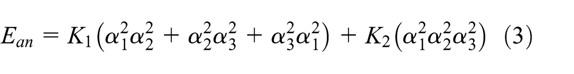
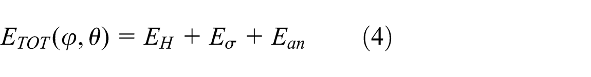
Based on the energy-based constitutive model, the total energy with an applied stress and a magnetic field is determined by the sum of the magnetic, the stress-induced, and the magnetocrystalline anisotropic energies along different orientations of magnetization. Five material constants are required in this model, namely, the cubic crystalline anisotropy constants K
1 and K
2, the magnetostrictive constants λ100 and λ111, and the saturation magnetization Ms
. Assuming that the magnetic field (H) is applied along the direction cosines (

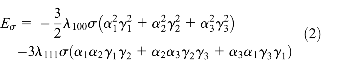
The total energy (
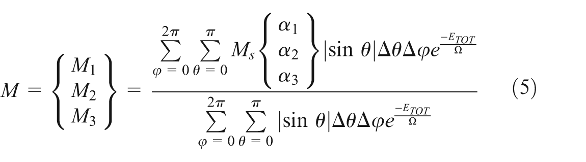
The magnetization components, the magnetic induction, and the magnetostriction components can be calculated through equations (5), (6), and (7), respectively


Classical laminated beam theory with induced-strain actuation
The classical Euler–Bernoulli beam theory can be used in the structural analysis of the laminated beams with the following assumptions 17 :
There is no flaw or gap in the bond layer between the laminae, and the thickness of the layer is ignored.
There is no shear deformation in the bond layer.
The bond layer has infinite stiffness so that the composite beam behaves like a single lamina with integrated properties.
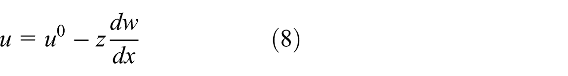
Figure 1 shows a Galfenol–aluminum laminated composite beam. In general, the composite beam may undergo both extension and bending. Therefore, the axial displacement along the x-direction may be expressed using equation (8), where

A Galfenol–aluminum laminated composite beam.
Similarly, the total axial strain (

Assume that a composite beam with


It should be noted that the mid-plane is considered as the plane where z = 0. For an active material with free strain (

If we substitute equation (12) into equations (10) and (11) and integrate over the thickness of each lamina, the force and the moment balance in the beam can be expressed as equations (13) and (14), respectively. It is assumed that Young’s modulus and the width of each lamina do not vary across the thickness of each lamina


Equations (13) and (14) can be combined and written as equation (15), which can be used to obtain the mid-plane strain and the curvature of the composite beam

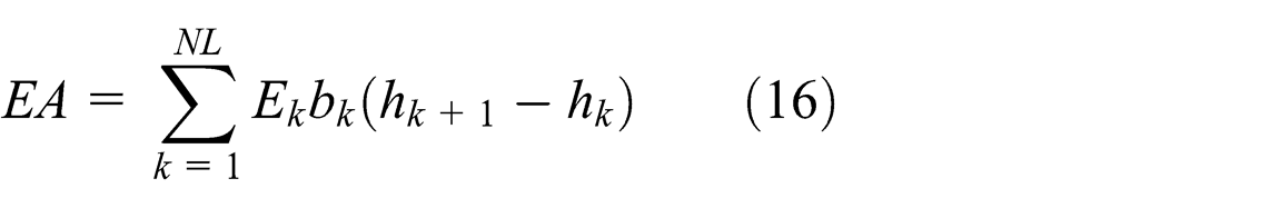
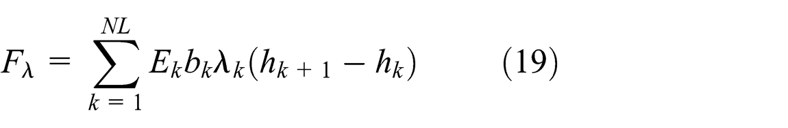
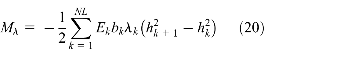
The terms in equation (15), including the extensional stiffness (


Equation (15) shows that the axial and the bending displacements can be coupled in a laminated composite beam. In addition, the active strain in any of the laminae produces both the extensional force and the bending moment, which deform the active composite beam.
Comparison with other models
The proposed ECMM was compared with the theoretical models developed by De Lacheisserie, 18 Klokholm and Jahnes, 19 Guerrero and Wetherhold, 13 and Datta. 20 The dependence of the normalized tip displacement on the thickness ratio was investigated and compared among various models.
The results are displayed in Figure 2. The models of Lacheisserie and Klokholm both predicted a monotonical increase with the increase in the beam thickness ratio. In the predictions by Guerrero, Datta, and ECMM, when the thickness ratio increases, the magnitude of the normalized tip displacement will increase at the beginning and then decrease after reaching the maximum value. They predicted similar normalized tip displacements only at high thickness ratios. Due to the integration of an ECMM with the classical laminated beam theory, the ECMM provided a more sensitive modeling framework for the response of the magnetostrictive composites to the thickness ratio.

The dependence of the normalized tip displacement on the thickness ratio.
Analysis of test setup and experimental results
Description of the experiments
Several prior works have shown the application of the Galfenol-driven cantilever beam, in which the Galfenol lamina was attached to other materials.7,21 However, neither experimental work nor theoretical estimation has been performed to help in understanding the effect of the composite stiffness and the operating conditions on the actuation performance of such beam. Based on the above theory, the optimal stiffness and the magnetic field criteria could be obtained to produce the maximum bending displacement.
The length, the width, and the thickness of the Galfenol lamina are measured along the crystallographic
In order to study the effect of composite stiffness on the out-of-plane tip displacement (

Based on equation (9), the curvature can be obtained from the difference of the strains on the surfaces of passive and active layers divided by the thickness (
Aluminum laminae with thicknesses of 0.46, 0.91, 1.85, 3.71, and 7.43 mm are fabricated using wire electrical discharge machining (EDM) to make the Galfenol–aluminum unimorphs, which are expected to have different maximum values of tip displacements. A series of experiments are conducted to evaluate the performance of these unimorphs with the actuators which are subject to bending.
Mechanical analysis of test setup
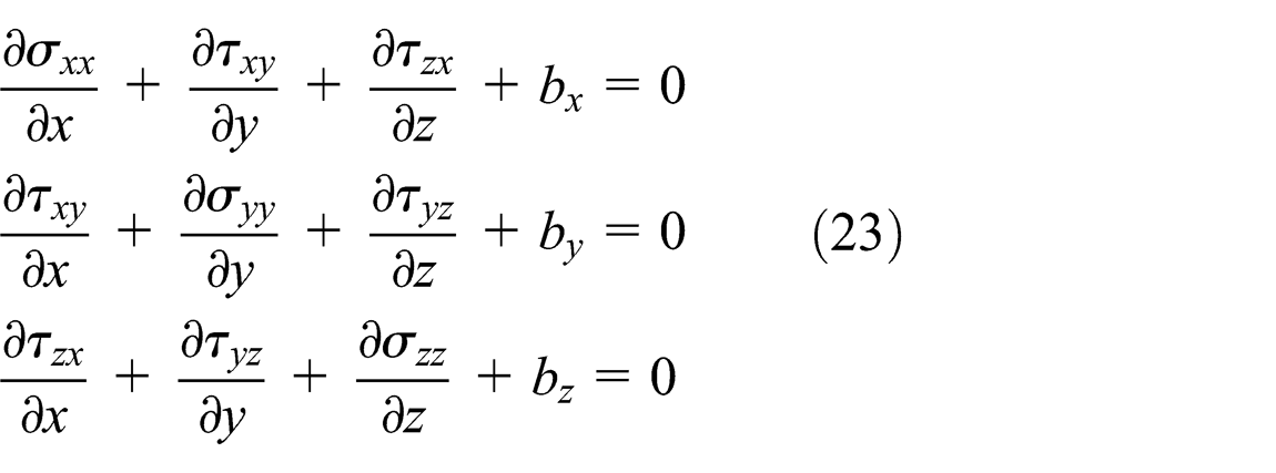
The structure of the experimental setup is analyzed using the FE method. It is to find whether the location of strain gages is appropriate for measuring the desired strain or the strain gages measured an average strain from a large spatial strain distribution. Furthermore, since the aspect ratio of several unimorphs is not strictly conformed to the suggestion in the Euler–Bernoulli beam theory, it requires to perform a three-dimensional (3D) structural analysis using FE method to find the relative magnitudes of the stress components in either the Galfenol or the aluminum layers. The 3D structural FE analysis is performed using the structural mechanics module in COMSOL multiphysics. The “Solid, Stress-Strain” static analysis and the Lagrange-quadratic elements are adopted. The mechanical boundary value problem is solved by COMSOL using the static stress equilibrium shown in equation (23), where bx , by , and bz are the components of the body forces along the x-, y- and z-directions, respectively
The strain displacement relationships for small strains are as shown in equation (24)

The strain compatibility, shown in equation (25), serves as the subsidiary condition

The stress–strain constitutive relationship is described by equation (26), where [c] is the stiffness matrix and


The stiffness matrix for isotropic materials can be obtained from Young’s modulus (E) and Poisson’s ratio (
The effect of free strain on the unimorph is studied, where the Galfenol and aluminum layers are of the same length. The clamping of one end of the composite structure is simulated by assigning a “fixed” boundary condition at one end along the span of both the Galfenol and aluminum layers, whereas all other faces are assigned to a “free” boundary condition.
The simulation is performed with five different aluminum thicknesses which are used in the experiments. Figure 3 shows the simulation result with a 7.43-mm-thick aluminum layer, which represents the extreme scenario with the most prominent 3D effects. It is evident from Figure 3 that the strain on the free surfaces for both the Galfenol and the aluminum layers is fairly uniform except the location close to the clamped end and the tip of the composite beam. The existence of the uniform strain makes these areas suitable for strain gage bonding.

Strain distribution on the free surfaces of the Galfenol and the aluminum layers.
The Euler–Bernoulli beam theory is only applicable if the shear stresses are negligible. It is necessary to find the maximum magnitude of all the stress components in the unimorphs with different thicknesses. In all the five unimorphs, the most dominant stress component was
In order to further compare the predictions of 1D beam theory and 3D FE structural models, the normalized tip displacement is calculated using both models. In order to calculate the normalized tip displacement (
Predicted values of the normalized tip displacement.

1D: one-dimensional; 3D: three-dimensional.
The simulated values of the normalized tip displacements show that the maximum error between 1D and 3D predictions is 4%, which indicates that the aspect ratio of the unimorphs does not have a significant effect and so complete 3D structural analysis might not be the necessary in the analysis of the unimorphs.
Effects of the laminate thickness
The unimorphs comprised a Galfenol layer with a constant thickness and an aluminum layer with a varied thickness, which can alter the stiffness of the unimorph. Actuator characterization is expected to identify the optimal stiffness and the optimal magnetic field, which may produce maximum bending displacement in the unimorph. The magnetic field and the aluminum layer thickness in the unimorphs are considered as control parameters, and their effects on the strain, the Galfenol, and the aluminum surfaces are analyzed. These strains are used to calculate the tip displacements of the beam.
The non-load actuator tests are performed to study the effect of the magnetic field on the actuation of the unimorphs with different stiffnesses. The composite stiffness varied with the thicknesses of the aluminum layer, which are 0.46, 0.91, 1.85, 3.71, or 7.43 mm. The same thickness of the Galfenol lamina with 1.86 mm is used in all the unimorphs. The Galfenol and the aluminum pieces are laminated using Vishay M-Bond. The aluminum layer with a length of 35 mm, a width of 8.4 mm, and an overhang of 10 mm is inserted into a clamping device.
The effects of aluminum layer thickness on the strain measured on the free surfaces of the Galfenol and the aluminum layers are shown in Figures 4 and 5, respectively. The strains are expressed as a function of the applied magnetic field.
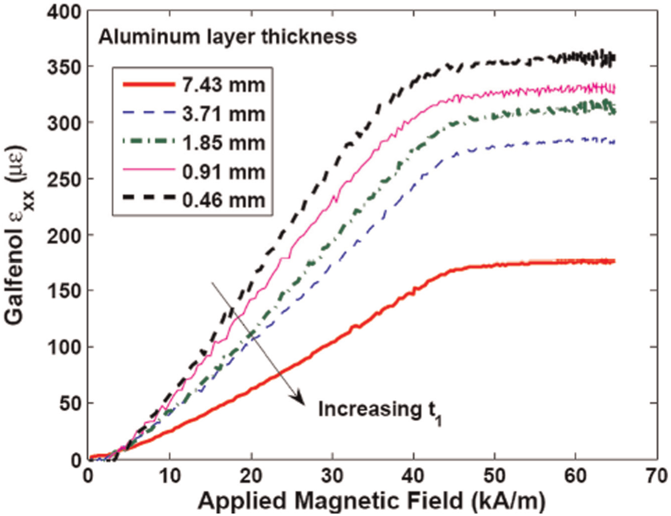
The dependence of the strain measured on the surface of Galfenol on the applied magnetic field.
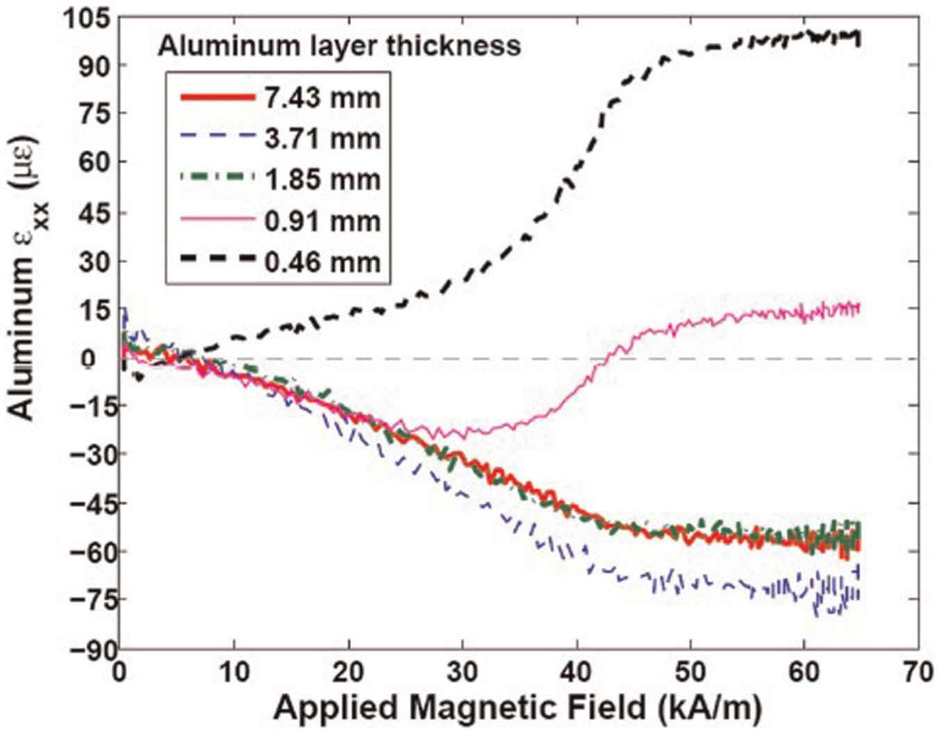
Strain measured on the surface of aluminum as a function of applied magnetic field.
Figure 4 shows that for each unimorph, the strain on the Galfenol surface increases monotonically till saturation at a certain magnetic field. This behavior is similar to the
Figure 5 shows that the behavior of strain on the aluminum surface is somewhat different from the strain on the Galfenol surface. In general, for all the unimorphs, the magnitude of the strain is increased with the increase in the magnetic field until saturation. However, the monotonic behavior of the strain changes with the increase in the magnetic field and the monotonic behavior of the saturation strain changes with the increase in the aluminum layer thickness as shown in Figure 4 and it does not hold true for Figure 5.
For t 1 = 7.43, 3.71, and 1.85 mm, the strain on the aluminum surface decreases monotonically with the increase in the magnetic field, thereby clearly exhibiting a bending of these unimorphs. For t 1 = 0.91 mm, the strain initially appears to decrease with the increase in the magnetic field. When the magnetic field is increased over 30 kA/m, the strain will increase with the increase in the magnetic field and even changes the sign at 43 kA/m. This behavior indicates that the unimorph predominantly deforms due to bending at lower magnetic fields, but the effect of bending reduces at higher magnetic fields (larger than 30 kA/m). Finally, for the fields higher than 43 kA/m, the deformation is dominated by extension which is evident from the same sign of the strain on both the Galfenol and the aluminum surfaces. For t 1 = 0.46 mm, the strain on the aluminum surface is positive at all the magnetic fields, which shows that this unimorph predominantly deforms by extension.
The negative values of the saturation strain on the aluminum surface increase when t 1 is changed from 7.43 to 3.71 mm, but decrease with further reduction in t 1 to 1.85 mm. The saturation strains are positive with t 1 = 0.91 and 0.46 mm and increase with the decrease in t 1. Note that although the change in t 1 follows a geometric progression, that is, each being the half of previous value, no such monotonic behavior can be observed in the saturation strain values with different t 1. It appears that the saturation strain varies very little with large aluminum thicknesses, but varies significantly with relatively small aluminum thicknesses.
In order to visualize the extension and the bending of each unimorph separately, the strains shown in Figures 3 and 4 could be used to calculate the mid-plane strain (


Figure 6 shows the dependence of the mid-plane strain in the unimorphs on the applied magnetic field. For a given aluminum layer thickness, the mid-plane strain monotonically increases with the increase in the magnetic field. For a given magnetic field, the mid-plane strain monotonically increases with the decrease in the aluminum layer thickness. The unimorph structure tends to extend more freely with a decrease in aluminum layer thickness since the contribution of aluminum layer to the composite stiffness decreases. Hence, the mid-plane strain asymptotes to the free strain of the Galfenol layer with the decrease in aluminum layer thickness, which is highlighted by the free strain of Galfenol as shown in Figure 5.

The dependence of the mid-plane strain on the applied magnetic field.
Figure 7 shows the dependence of normalized tip displacement in the unimorphs on the applied magnetic field. For a given aluminum layer thickness except t 1 = 0.46 mm, the mid-plane strain monotonically increases with the increase in the magnetic field. This apparently anomalous behavior can be explained by combining the information in Figures 3 and 4 and using them in equation (29). For t 1 = 0.46 mm, the strain on both the Galfenol and the aluminum surfaces is of the same sign.

The dependence of the normalized tip displacement on the applied magnetic field.
Hence, the magnitude of the normalized tip displacement can decrease with the increase in the magnetic field if the change rate of the strain with respect to the magnetic field is higher in the Galfenol layer than in the aluminum layer. It can be deduced that this effect may be even more prominent with a thinner aluminum layer.
At magnetically saturated conditions, the normalized tip displacement increases when the t 1 value is decreased down to 1.85 mm. For the t 1 value smaller than 1.85 mm, the normalized tip displacement decreases with the decrease in the t 1 value. This trend is consistent with the 1D and 3D simulations shown in Table 1.
The underestimation of the experimental results by both 1D and 3D models is possibly due to the omission of the effect of the bond layer between the Galfenol and the aluminum layers and any associated imperfection or local delamination in the bond. The bond layer can be modeled as an additional layer between the Galfenol and the aluminum layer in the Euler–Bernoulli composite beam. The effect of the bond layer on the normalized tip displacement of the unimorphs can be estimated as a function of Young’s modulus of the cured bond and the bond layer thickness as shown in Figure 8. Since the exact value of Young’s modulus of the bond is unknown, the simulation is performed using possible range of values for typical cured cyanoacrylate glues. Moreover, since the thickness of the bond layer may vary in different unimorphs, the simulation is performed with a range of bond layer thickness. Figure 8 shows that the normalized tip displacement increases with the increase in the bond layer thickness and the bond’s Young’s modulus. In addition, the normalized tip displacement regarding the bond layer significantly differs from the ideal condition neglecting the bond layer. The simulation results in Figure 8 provide the explanation for the higher saturation values of the normalized tip displacement calculated from the experiments compared to the values predicted by the ideal models which ignore the effect of the bond layer.

Effect of the thickness and Young’s modulus of the bond layer on the normalized tip displacement.
Conclusion
A nonlinear model is developed to predict the behavior of the laminated cantilever beam with Galfenol adhered to an aluminum layer. The laminated Galfenol-driven magnetostrictive cantilever beam subjected to magnetic fields and in-plane mechanical axial and bending was studied.
First, in this model, the total energy with an applied stress and a magnetic field is determined as the sum of the magnetic, the stress-induced, and the magnetocrystalline anisotropic energies along different orientations of magnetization. The laminated Galfenol-driven magnetostrictive structure is built based on the design criteria set by beam theory with induced-strain actuation.
Second, the structure of the experimental setup is analyzed using the FE method. The simulated values of the normalized tip displacement show that the maximum error between the 1D and 3D predictions is 4%. It supports that the aspect ratio of the unimorphs does not have a significant effect on the simulation results and a complete 3D structural analysis might be unnecessary.
Finally, the effect of the stiffness of the non-magnetic layers and the actuating magnetic field on the actuator performance is studied. Simultaneously, the bond layer can be modeled as an additional layer between the Galfenol and the aluminum. The results show that the normalized tip displacement increases with the increase in the bond layer thickness and the bond’s Young’s modulus. And the normalized tip displacement regarding the bond layer significantly differs from the ideal condition neglecting the bond layer.
Footnotes
Academic Editor: Ruey-Jen Yang
Declaration of conflicting interests
The authors declare that there is no conflict of interest.
Funding
The authors would like to acknowledge the financial supports from the National Natural Science Fund of China (Grant Nos 51165035, 51175395 and 51205293), the Youth Science Fund of Jiangxi Province Office of Education of China (Grant No. GJJ11247), Guangxi Key Laboratory of Manufacturing System & Advanced Manufacturing Technology (Grant No. 11-031-12S05), MoE Key Laboratory of Metallurgical Equipment and Their Control (Grant No. 2013B09), and the Youth Science Fund of Jiangxi Province (20114BAB216006).