
Abstract
This study investigates the lubrication characteristics of a textured bearing sliding on a porous layer. To properly implement the porous layer effect in the bearing, the Brinkman-extended-Darcy model is employed, which results in a modified Reynolds equation. This equation is then evaluated to examine the effects of the porous layer’s material and geometric properties on the lubrication characteristics through the use of (semi-)analytic and numerical approaches. The cavitation effect is reflected in the numerical treatment of the model equation, and an adaptive finite difference scheme is employed to efficiently model the bearing system with finite dimples that may be far smaller than the overall bearing dimensions. Along with the variation trends of the bearing performance with respect to the material and geometric properties of the porous layer, the pattern effects of textured surfaces on the bearing performance indices (load capacity and equivalent friction coefficient) are also thoroughly investigated. Here, the pattern comprised a set of regularly spaced identical dimples either in semi-spherical or semi-ellipsoidal shape, and the effects of size and orientation of the dimples are comprehensively explored to separately identify their influence on the bearing performance indices.
Keywords
Introduction
Most of the machinery used in modern industry strongly demands the use of environmentally conscious or energy-efficient components, including various moving small components, which are directly or indirectly in contact with each other. The resulting friction and wear at the contact–sliding interface may be the most important factor affecting the energy efficiency for these moving components. Surface texturing technology is one prominent method to reduce friction and wear and thus improves the energy efficiency, by changing lubrication characteristics at the interface between the components in relative movement. Maintaining appropriate lubrication on a sliding surface can be accomplished by using a porous material. In the oil-impregnated bearings widely used in many machines where longevity is sought, a thin porous layer is coated on the bearing surface to reserve excessive oil and enhance the bearing reliability.
Studies on hydrodynamic lubrication have a long history. Among these studies, the Reynolds equation, which was derived by introducing assumptions such as the incompressibility of the lubricant, thin-film geometry, and negligence of body force and fluid inertia along with the continuity conditions into the Navier–Stokes equation, has been one of the most widely used theories for studying lubricant behaviors of various applications. This Reynolds equation is also used to analyze the lubrication characteristics of textured surfaces.1–5
In a porous region, however, the standard form of Reynolds equation cannot be directly employed, and it should be modified with the constitutive equation that governs the fluid behavior in such a porous region. The fluid flow behavior in porous media was theoretically explained first by Darcy. 6 Using the Darcy equation, Morgan and Cameron 7 theoretically studied the hydrodynamic lubrication problem in short porous journal bearings. Later, Cameron et al. 8 conducted an experiment to support the validity of the analytic solution obtained in their earlier study. 7 Capone 9 attempted to obtain the solution for the flow dynamic lubrication problem with a long porous bearing using the theoretical approach used by Morgan and Cameron. 7 Then, Rouleau 10 enabled the boundary conditions to be satisfied at the open ends by imposing a zero-pressure condition. Rhodes and Rouleau 11 examined the performance of a narrow porous bearing with sealed ends using the Darcy equation. Murti12–14 used the preceding results to analyze long porous bearings and then extended the problem to short, finite porous bearings. Tichy 15 proposed a lubrication model sliding on the thin film on a porous layer using the Darcy equation combined with the Reynolds equation.
The rheological effects of an interfacial plane between the porous medium and free flow region were first studied by Beavers and Joseph. 16 They performed an experiment to identify the boundary conditions at the interfacial plane. In their experiment, they observed slip flow in the boundary layer of the interfacial plane and thereby confirmed that the Darcy equation is not sufficient to reflect the velocity slip phenomenon on the lubrication problems coupled with porous media. Murti 17 derived a modified Reynolds equation using the criterion proposed by Beavers and Joseph 16 and introduced the velocity slip phenomenon into the analysis of narrow porous bearings. Chandra et al. 18 also considered the velocity slip phenomenon to theoretically identify the static and dynamic characteristics of a plane porous journal bearing. Also, Srinivasan 19 performed an analysis on axially undefined porous journal bearings using a similar theoretical basis to that of Beavers and Joseph. 16
Brinkman 20 pointed out that the Darcy equation ignores viscosity shearing stress on the fluid volume element. He argued that the Darcy equation cannot be effectively applied to a highly permeable porous medium because the error due to viscosity shearing stress rapidly increases with increasing permeability. To make up for this gap, he proposed the Brinkman-extended-Darcy equation that takes the viscous force on the fluid volume element into account. Later, Hamdan and Barron 21 compared the Darcy model and the Brinkman-extended-Darcy model in their study. Neale and Nader 22 found that the Brinkman-extended-Darcy equation can cause a remarkable change in the lubrication characteristics due to the inclusion of a viscous shear term that can influence the free flow region, even if the porous layer is thin. Later, Vafai and Kim 23 obtained an exact solution for the interfacial fluid flow problem between the porous medium and the free flow region. Using this solution, Nield 24 verified that shear stress continuity condition is not necessary at the interface. Lin and Hwang 25 employed the Brinkman-extended-Darcy model in their short porous journal bearing analysis in the hydrodynamic lubrication regime.
On the other hand, Ochoa-Tapia and Whitaker26,27 performed both theoretical and empirical studies on the stress jump condition and effective viscosity in the boundary layer between the porous medium and the free flow region by introducing a volume averaging technique. Li 28 proposed a fluid flow model to solve the thin-film lubrication problem on porous media by extensively using the Brinkman-extended-Darcy equation incorporated with the stress jump condition and the viscosity ratio.
In this study, we performed an analysis on the planar bearing with a textured surface sliding over a porous layer using the modified Reynolds equation incorporated with the Brinkman-extended-Darcy model. 20 The material properties including permeability, stress jump factor, and viscosity ratio are varied, dependently or independently, to examine their effects on the bearing characteristics including the load capacity (LC) and the equivalent friction coefficient (EFC). To find valid physical parametric ranges for the modified Reynolds equation, a parametric compatibility condition is also derived here (Appendix 1). The modified Reynolds equation along with this parametric compatibility condition is derived in a (semi-)analytic manner and solved/evaluated through the use of several numerical methods.
The patterns textured on a surface in this study are modeled as regularly spaced semi-ellipsoidal or semi-spherical dimples, and the size and orientation of the dimple are changed to examine their effects on the aforementioned bearing characteristics.
In a flow analysis of a patterned thin channel that includes diverging portions, treatment of cavitation may be an important ingredient for physically plausible results. In this study, the cavitation phenomenon is reflected through a numerical relaxation method, 29 where the Gauss–Seidel iteration method is extensively used.
Governing equations
The planar bearing system under consideration is composed of a textured surface abutting a flat surface coated with a thin porous layer. The schematics of the present bearing system are shown in Figure 1(a) and (b).

Schematic of the textured/porous planar bearing model: (a) three-dimensional shape and (b) cross-sectional view in two dimensions.
As shown in Figure 1(a), in the present planar bearing model, a thin porous layer, with thickness δ, is covered over the upper surface of the bottom plate moving with velocity components of
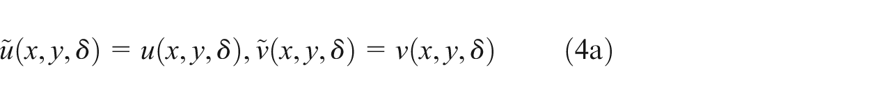
In order to derive a proper lubrication equation for the model explained above, the following Brinkman-extended-Darcy constitutive model 20 is introduced first


where


where
To make the present analysis general and convenient, the following dimensionless parameters are introduced

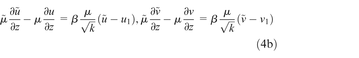
Using equation (6) and the mass conservation law to an infinitesimal fluid element in the film, the following modified Reynolds equation can be obtained
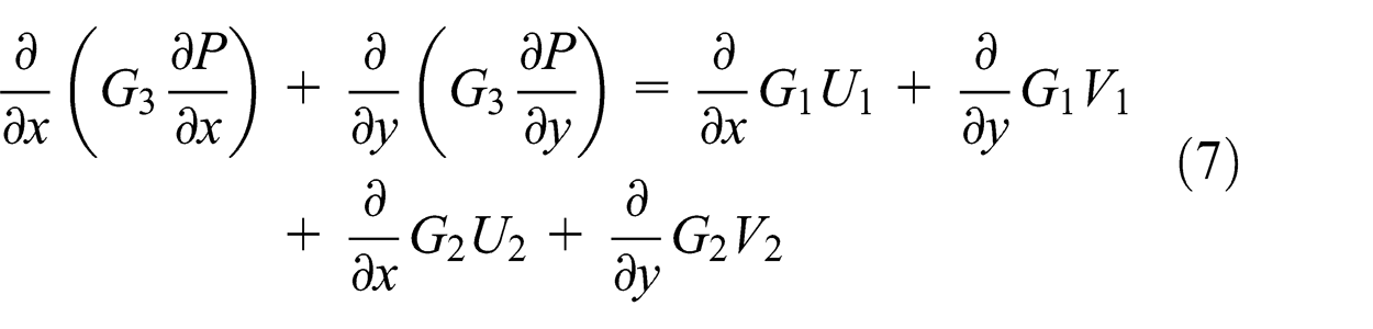
where


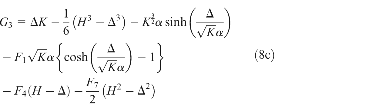
In equation (8),
Note that these equations are not the same as those in Li 28 due to the differences in the bearing configuration and the manner of derivation; however, they are consistent with each other.
As can be clearly seen in Equation (8),
The two most important figures of merit for the performance measure of the plain sliding bearing (bearing performance indices) may be the LC and the EFC. Here, the LC (or
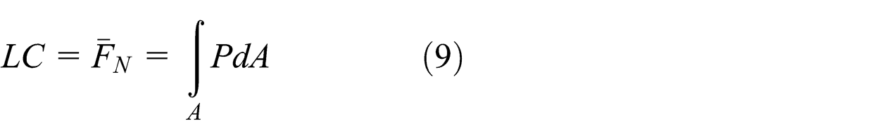
where the integral domain A means the area of the textured bearing surface.
The EFC (or
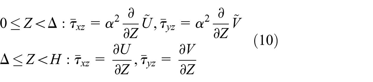
The force components in two tangential directions at the upper channel surface (i.e. two friction force components) can be obtained, namely


which result in the EFC as

Discussion of results
Effects of viscosity ratio, stress jump factor, and permeability on the lubrication characteristics of the planar journal bearing with a porous layer
In order to trace the effects of the viscosity ratio (
Case I: (
Case II: (
The detailed geometric and operational conditions used in this study are listed in Table 1.
The geometric and operational conditions for case studies (dimensionless).
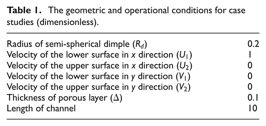
In this sub-section, a total of 25 semi-spherical dimples with dimensionless radius of 0.2 are assumed to be patterned on the top plane of the bearing. Under the same conditions, the LC and EFC values for nonporous bearings (
For the discretization of the analysis domain into meshes, we employed an adaptive mesh refinement scheme. This scheme can provide a way for adapting the numerical precision/resolution based on the requirements for the underlying problem in specific analysis domains that need precision while leaving the other domains at lower levels of precision or resolution. In this study, we divided the analysis domain (bearing surface) into three subdivision surface groups: (1) surfaces of dimples that require the finest meshes, (2) surfaces far away from the dimples that allow the coarsest meshes, and (3) surfaces in the near neighborhood of the dimples that require middle-class meshes. Due to this meshing scheme, the mesh number in each sub-surface tends to vary depending on the configuration of the pattern. For all case studies performed in this article, the total mesh number was kept large (not smaller than 16,000) enough to ensure the convergence and precision of the present analysis.
Case I
Figure 2(a) and (b) shows the velocity and shear stress variations as a function of fluid film thickness for several stress jump parameter values (
As expected, Figure 2(a) clearly shows that the maximum velocity in the free flow region increases with
Figure 3(a)–(d) shows the variations of LC, with several K values and
Figure 4(a)–(d) shows the EFC variations with respect to
Case II.
Figure 5(a)–(c) shows the LC variations with respect to K for fixed

(a) Velocity profiles and (b) shear stress variations for various stress jump parameter values (with dP/dX = −10, H = 1,

Load capacity variations for Case I with (a)

Equivalent friction coefficient variations for Case I with (a)

Variations in load capacity for Case II with (a)
Figure 6(a)–(c) shows the EFC variations with respect to K for Case II with the same set of

Variation in equivalent friction coefficient for Case II with (a)
Case studies of dimple size on the lubrication characteristics of a porous bearing textured with either semi-ellipsoidal or semi-spherical dimples
In this sub-section, the effects of dimple size on the lubrication characteristics of a porous bearing are investigated, where the bearing is textured to contain either semi-ellipsoidal or semi-spherical dimples. The geometric and operating conditions used in this section are listed in Table 2, and the parameter values for the porous layer are shown in Table 3. For the cases with semi-ellipsoidal dimples, only the length of the major axis (the axis aligned in the x direction) is changed, whereas the lengths of the other two minor axes (the other two axes aligned in y and z directions, respectively) are kept constant for computational convenience. Therefore, the carved semi-ellipsoids are in the shape of prolate ellipsoids of revolution (prolate spheroids) in this study. For notational convenience and unification, the length of the major axis is to be called, hereafter, the “radius” for a semi-ellipsoidal dimple. Furthermore, in order to be consistent with the previous case study, the viscosity ratio (
The geometric and operational conditions used to investigate dimple size effect.

The porous layer parameters used to investigate dimple size effect.
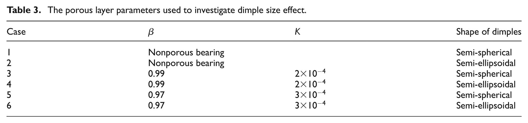
Here, Cases 1 and 2 are associated with the nonporous bearing, whereas Cases 3–6 are associated with the porous bearing with either
Figure 7(a) and (b) represents the LC and EFC variations, respectively, as a function of the dimple radius. The LC values shown in Figure 7(a) tend to increase almost linearly with dimple size within the present computation range regardless of dimple shape. However, the increasing rate of LC with semi-spherical dimples is shown to be greater than that with semi-ellipsoidal dimples.
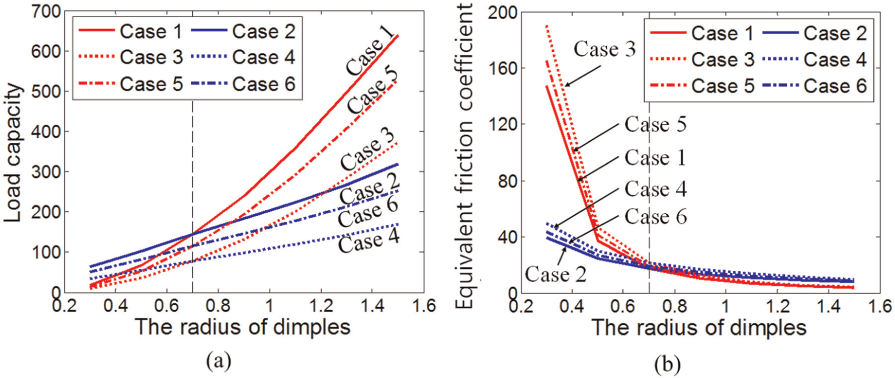
Variations in (a) load capacity and (b) equivalent friction coefficient with respect to dimple radius.
For computations for the cases associated with semi-ellipsoidal dimples, only
In this situation, the LC values for Cases 1 and 2, which are the nonporous bearing cases patterned with semi-spherical dimples and semi-ellipsoidal dimples, respectively, are higher than those for the porous bearing counterparts. On the other hand, for the porous bearing cases associated with semi-ellipsoidal dimples, the LC values for Case 4 are smaller than those for Case 6.
Figure 7(b) shows the trend in EFC variations with respect to the dimple size. Unlike the trend in LC variations, the EFC value decreases with dimple radius. Furthermore, it can be observed that when the dimple radius is smaller than 0.7, the EFC values for Cases 1, 3, and 5 (the cases associated with semi-spherical dimples) are larger than those for their respective semi-ellipsoidal counterparts, that is, Cases 2, 4, and 6, respectively. After passing through the cross-over point of the radius (0.7), the EFC values for the cases associated with semi-spherical dimples are smaller than those with their semi-ellipsoidal counterparts. In addition, for Cases 3–6, in which a porous layer exists, the same trend as examined in section “Case studies of dimple size on the lubrication characteristics of a porous bearing textured with either semi-ellipsoidal or semi-spherical dimples” can be observed. Like the trend that the EFC value for
Major axis orientation effects of the semi-ellipsoidal dimple on the bearing’s lubrication characteristics
In this section, a series of case studies are performed to investigate the lubricating effects generated due to the orientation of the major axis of the textured semi-ellipsoidal dimples. The geometric attributes of dimples and operating conditions of the bearings are listed in Table 4. In brief, the dimple number is fixed to be 25 for all cases and the major axes of the patterned semi-ellipsoids are set to be parallel with the x-axis (
Geometric attributes of dimples and operating conditions of bearing.

Porous layer parameters used to investigate the size effect of the textured semi-ellipsoidal dimples.

Figure 8(a) and (b) shows the variations in LC and EFC with respect to the variations in

Variations in (a) load capacity and (b) equivalent friction coefficient with respect to
Alternatively, the trend for EFC variations is opposite to that for LC variations; the EFC values increase with
Conclusion
In this study, the pattern effects on the lubrication characteristics, such as the LC and EFC of a sliding bearing incorporated with a porous layer, are thoroughly examined. Here, the pattern comprised a set of regularly spaced identical dimples either with semi-spherical or semi-ellipsoidal shapes, and the size and orientation of the patterned dimples are independently varied to examine their effects separately. Furthermore, the effects of the porous layer’s material and geometric properties such as the permeability (K), stress jump parameter (
Overall, the LC (or EFC) value for the bearing with a porous layer is lower (or higher) than that without the porous layer under the same parametric and geometric conditions. In addition, with the fixation of other parameters, the LC (or the EFC) value decreases (or increases) with the increase in the stress jump parameter (
Two representative dimple shapes (one semi-spherical and the other semi-ellipsoidal) are considered for investigating their configurational effects on the lubrication characteristics. The LC (or EFC) values increase (or decrease) almost linearly with the dimple size for both dimple shapes. However, the increasing (or decreasing) rates of the LC (or EFC) with the size of the semi-spherical dimple are much higher than those of the semi-ellipsoidal dimple.
The orientation of the major axis of the semi-ellipsoidal dimple (
Footnotes
Appendix 1
Appendix 2
Academic Editor: Jose R Serrano
Declaration of conflicting interests
The authors declare that there is no conflict of interests regarding the publication of this article.
Funding
This work was supported by the Industrial Strategic technology development program (10039982, Development of next-generation multi-functional machining systems for eco/bio components) funded by the Ministry of Trade, Industry and Energy (MI, Korea) and National Research Foundation of Korea (NRF) grant funded by the Korea government (MSIP) (No. 2014R1A2A1A1 1049579).