
Abstract
Machining-induced residual stress has significant influence on the performance of the parts. Extensive studies about machining-induced residual stress concerning many factors have been carried out but few focused on the role of initial stress distribution in cutting process. In this study, a finite element method study on the influence of initial stress on machining process is carried out. A combined method to obtain the parameters in Johnson–Cook constitutive model was introduced and verified with face milling experiments and finite element method simulations. And with this carefully established finite element method model, the influence of the value and distribution range of initial stress on cutting process was studied. The results show that the initial tensile stress makes the cutting stress distribution within the workpiece become more tensile and diminishes the cutting forces and tool tip temperature, while initial compressive stress has opposite effects. The value and distribution range of initial stress determines the strength of this influence. On the other hand, the machining process also results in the partial release of initial stress in the bulk material.
Introduction
Residual stress in superficial and subsurface layers of a machined component is an important aspect of surface integrity because it significantly influences the fatigue life, corrosion resistance, and abrasive resistance of the parts.1–3 Moreover, residual stress is a key factor influencing the machining-induced deformation of thin-walled structures. 4 Thus, it is important to accurately predict and effectively control the machining-induced residual stress.
Since the 1950s, many investigations have been carried out on machining-induced residual stress. In most experimental researches, the residual stress is regarded as a function of cutting parameters, tool parameters, or the properties of the workpiece material, and the influence of cutting parameters is of the biggest interest. Outeiro et al. 5 concluded and analyzed many researches of this kind and further conducted a comprehensive study on machining residual stress and its correlation with cutting parameters such as cutting speed, feed and depth of cut. Jacobus et al. 6 studied the influence of tool parameters on residual stress. The relationship between residual stress and some characteristics of the workpiece materials, such as the hardness, 7 yield strength, 8 and chemical composition, 9 has also been studied. Many researches involve the combined effect of different parameters. For example, Qin et al. 10 studied the influence of various cutting fluids, cutting parameters, and rounded cutting edge radii on residual stress after turning. Based on the experimental observations, various empirical models have been proposed, such as second-order polynomial model 11 and logarithmic exponential polynomial model. 9 The experimental researches have contributed a lot to understanding the distribution law of residual stress, but with currently available equipment, it is difficult to track the formation process of machining-induced residual stress, and the accuracy of measurement is influenced by many factors due to the inherent complexity of residual stress. 3 The empirical models cannot reveal the formation mechanism of residual stress and can only be applied under certain conditions.
On the other hand, most experimental researches ignored the initial stress state in the workpiece, that is, the self-balancing inner stress state before machining, or just removed the initial stress in workpiece through annealing process. Actually, the forming and heat treatment of raw material, as well as the former machining processes, all influence the inner stress distribution of the workpiece, which may influence the final residual stress distribution. In the literature,5,12 the measured residual stress distribution along depth direction sometimes converges to a certain nonzero value, which may indicate the existence of initial stress within the workpiece. Liu et al. 13 found out that the cutting forces are influenced by pre-stress load, and it can be speculated that the initial stress distribution also influences the observables in machining process.
Finite element method (FEM), with its advantages of being able to precisely simulating the material behavior and providing a visualized interface, provides an access to understanding the detailed formation and evolution mechanism of residual stress. Hua et al. 14 simulated the influence of feed rate and parameters of the cutting edge on residual stress distribution. Jiang et al. 15 carried out a three-dimensional (3D) FEM study of the residual stress in end-milling, paying special attention on the influence of uncut chip thickness, and the results showed good accordance with the experiment results. Many similar studies were done with FEM, and some useful conclusions were drawn; however, most FEM studies set the initial workpiece state as stress-free, which omitted the influence of initial stress and is not in accordance with real machining conditions in most circumstances. Dattoma et al. 16 studied the effect of machining process on the residual stress field generated in welding process, in which the milling process was simplified as a stress relief process, ignoring its mechanical and thermal effects. Although the superficial layer, where the residual stress distribution is greatly influenced by machining, is relatively thin and usually less than 200 µm, 16 it may significantly influence the performance of the workpiece, for example, the fatigue life. 1 Li et al. 17 employed two cutting tools in their FEM analysis to model continuous feed milling process and showed that the stress field left by the former tool influences that of the latter. However, there are few studies that specified the influence of initial stress distribution.
In this article, the influence of initial stress on machining process and residual stress distribution is analyzed with a carefully established FEM model. The parameters in the Johnson–Cook (J-C) constitutive model were identified with a combined method which takes advantage of both pressure bar tests and orthogonal cutting tests, and the accuracy of the FEM model was verified with experiments measuring cutting forces. This research shows that the initial stress state influences the machining process and the superficial residual stress distribution, meanwhile the machining process may cause the release of initial stress within the bulk material.
Combined identification method for parameters in J-C model
Constitutive model of workpiece material is a key factor influencing the simulation accuracy.18,19 During the past decades, scholars have put forward several constitutive models suitable for metals, among which J-C model, 20 shown as equation (1), is now widely used in the simulation of machining process as it has concise mathematical expression and can properly reflect the strain hardening, strain rate hardening, and thermal softening properties of material
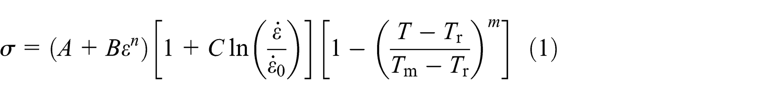
where
Pressure bar tests, including quasi-static pressure bar test and split Hopkinson pressure bar (SHPB) test, are commonly used method to acquire the data needed for identifying parameters in J-C model.21,22 But pressure bar tests can only reach a strain rate of the order of 102–103 s−1, which is much smaller than that in machining (up to 104–106 s−1). 23 To address this problem, there has been arising interest of extracting constitutive parameters directly from data measured in machining, especially through orthogonal cutting method (OCM). As it is difficult to measure stress and strain in machining directly, a theoretical model is needed to predict these variables with data easier to obtain, such as cutting forces and temperature. Tounsi et al. 24 modeled metal cutting process and proposed a methodology to identify the material coefficients of J-C model, which has been proved by several scholars.19,25 Yet, this theoretical model only calculates the data in the shear deformation zone, where the material undergoes large strain and high temperature. So, with this method, the relationship between strain and stress cannot be fully described at low-strain and low-temperature stage. Both pressure bar method and OCM have some disadvantages, and they usually need a reverse identification process and several iterations to modify the constitutive parameters before finally achieving a good accuracy.22,25 In this article, a combined method to obtain the constitutive parameters in J-C model is proposed that takes advantage of both pressure bar tests and orthogonal cutting tests. The combined method can be carried out following three steps.
Step 1: identification of strain hardening parameters
,
, and
To identify the strain hardening parameters, quasi-static pressure bar test is to be performed at room temperature, setting the strain rate as the reference strain rate. Hence, the J-C model can be simplified as equation (2)

Genetic algorithm (GA), which can be easily performed with MATLAB Optimization Toolbox, is recommended to identify these three parameters and the other two parameters in the following steps. With this tool, no complex mathematical deducing is needed. With proper trial values of the parameters, the so-called initial population in GA, and proper evolution rules, the optimized values can be obtained by finding the minimum value of the function expressed as equation (3)

where N is the number of strain or stress data obtained from the experiment, and i (=1, 2,..., N) is the index of the data.
Step 2: identification of thermal softening exponent
With SHPB tests at different temperatures, thermal softening exponent can be identified with GA or least square approximation (LSA) technique, setting the target function as equation (4). In all the tests, the strain and strain rate should be fixed as constants,

where M is the number of different temperatures, j (=1, 2,..., M) is the index of the data, and
Step 3: identification of strain rate factor
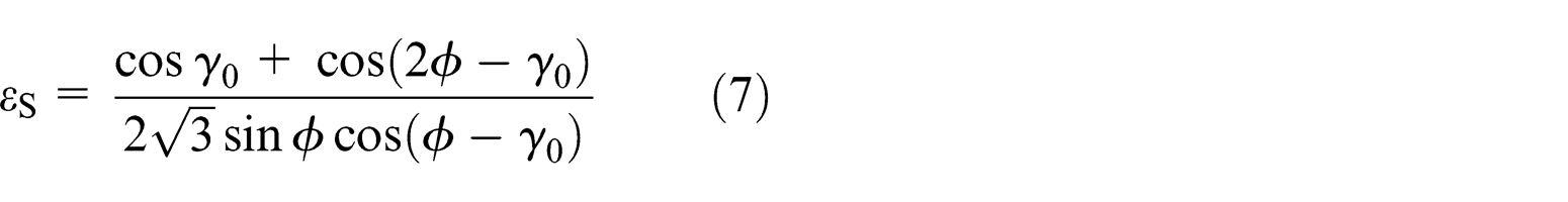
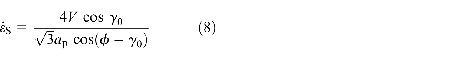
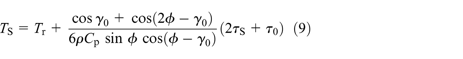
The strain rate hardening behavior is modeled with data from OCM tests and a theoretical model that can predict the strain, stress, and temperature in the first deformation zone with measured data, which have been well established by Tounsi et al. 24
The shear angle, which is critical in theoretical models, can be calculated with measured chip thickness

where
And the other parameters in first deformation zone can be obtained with equations reorganized according to the literature 24

where
As strain hardening and thermal softening parameters have been identified within the former two steps, the strain rate factor
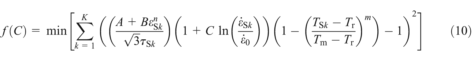
where K is the number of OCM tests and k (=1, 2,..., K) is the index of the data.
In this research, a Japanese standard alloy steel SCM440H was chosen as the workpiece material. Its chemical composition and mechanical properties are listed in Tables 1 and 2, respectively.
Chemical composition of SCM440H (% in weight).

Basic physical properties of SCM440H.

Lan et al. 22 carried out quasi-static pressure bar tests and SHPB tests on SCM440H, and the data were reprocessed in this research. Data from quasi-static pressure bar test at 0.001 s−1 strain rate were used to obtain the strain hardening parameters. And in studying the thermal softening effect, an electric oven was used to heat the specimen, and SHPB tests at strain rate of about 2500 s−1 were performed to obtain the data. Following steps 1 and 2, the strain hardening parameters and thermal softening exponent were identified: A = 500, B = 876.49, n = 0.54, and m = 0.7308. The fitting curve and measured data are shown in Figure 1(a) and (b).

Strain hardening and thermal softening data from experiments 22 and the fitted curve obtained with steps 1 and 2: (a) quasi-static test data and fitted curve and (b) thermal softening data and the fitted curve.
OCM tests were performed with SCM440H.
25
In this OCM experiment, cutting speed was 70–200 m/min, feed per rotation was 0.1–0.3 mm, and width of cut was set to be 2 mm. After measuring and processing the obtained data about cutting forces and chip thickness with equations (5)–(9), the calculated strain rate within the shear zone is between 1.027 × 10⁴ and 8.378 × 10⁴ s−1. With strain hardening parameters and thermal softening parameters obtained, and with equation (10), the strain rate factor
Experimental verification of the FEM model
To verify the proposed method, face milling experiments and the corresponding FEM simulation were carried out. The milling experiment was performed on a DMG machining center, DMU 60 monoBLOCK. The workpiece, whose dimensions is 100 mm × 30 mm × 15 mm, was fixed with a Kistler 9257B dynamometer via a specially designed fixture, as shown in Figure 2. The milling tool is a 100-mm-diameter FMP01-100-B32-TP22-06 disk cutter produced by ZCC.CT, with six TPKN2204PDFR inserts.
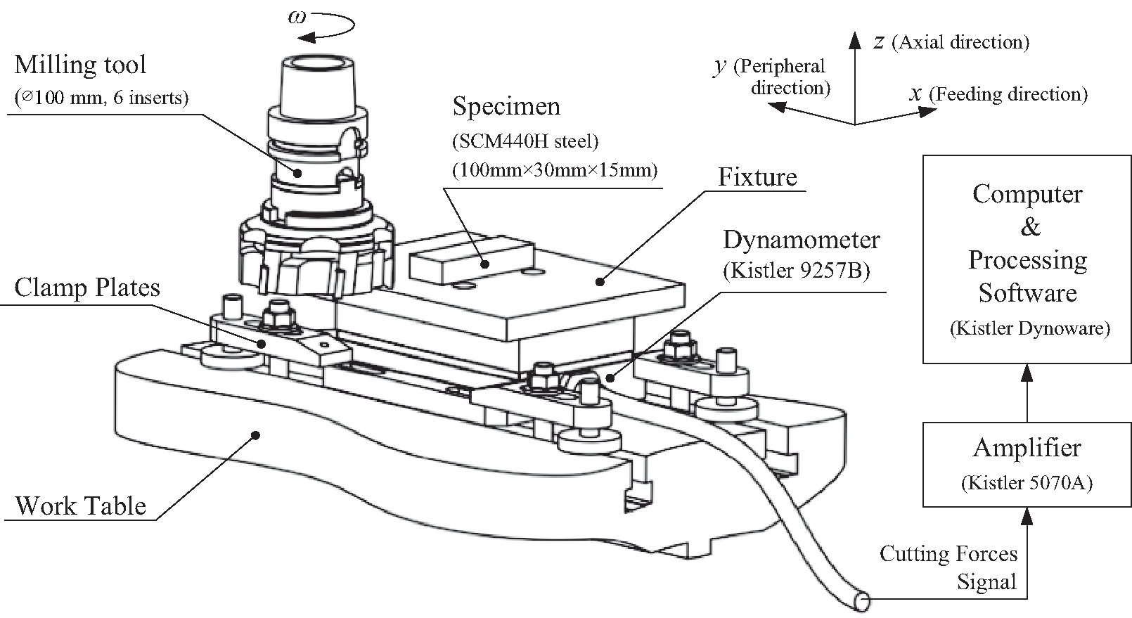
Setup for face milling tests.
The finite element software chosen in this study is Third Wave Systems AdvantEdge, with the J-C model obtained in this paper as a custom workpiece material model. To minimize the computing cost, only the effective parts of the tool and workpiece were modeled, and the geometry parameters were set as the same with that in experiment. The layout of simulation is shown in Figure 3(a). AdvantEdge uses the adaptive remeshing technology, which means that after each calculation step, the meshes on the workpiece will be regenerated according to the relative position between the tool and the workpiece, and the size of meshes near cutting edge was set to be 0.02 mm, and the meshes during cutting simulation is shown in Figure 3(b).
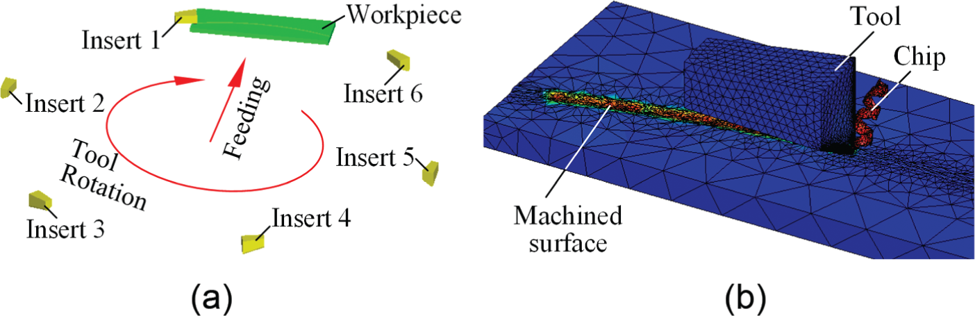
Settings of the face milling model in AdvantEdge: (a) layout settings and (b) meshing information and chip formation.
In this experiment, the tool diameter was much larger compared with the width of the workpiece, and the engaged cutting movement is almost vertical to the feeding direction during milling process. So, the force component in the feeding direction is very small and ignorable, and here, the cutting forces in the main cutting direction and axial direction are analyzed. The comparison between experiment and FEM simulation results is shown in Table 3. For most tests, the absolute simulation error of cutting forces is below 20 N, and the relative errors are quite small, with an average error valued at about 15%. On the whole, the simulation achieved good accuracy, which proved the reasonableness of the FEM and the obtained J-C model.
Comparison of experiment and FEM simulation results.

FEM: finite element method.
Influence of initial stress distribution
A group of orthogonal cutting simulations were done to analyze the role of initial stress distribution in machining process with AdvantEdge, mainly focused on the formation and evolution process of machining-induced stress, and the observables such as cutting forces and temperature. Uncoated carbide tool with 5° rake angle (α) and 10° relief angle (β) was chosen, and the edge radius (rε ) was set as 0.02 mm. The cutting parameters of the orthogonal cutting are shown in Figure 4(a), where a p is the width of cut, f z is the feed per rotation, and v c is the cutting speed (the tool was fixed, and the cutting movement is actually the movement of the workpiece). Figure 4(b) shows the original meshing information before cutting.

Parameters and meshing in FEM model of orthogonal cutting: (a) parameters in orthogonal cutting and (b) original meshing in AdvantEdge.
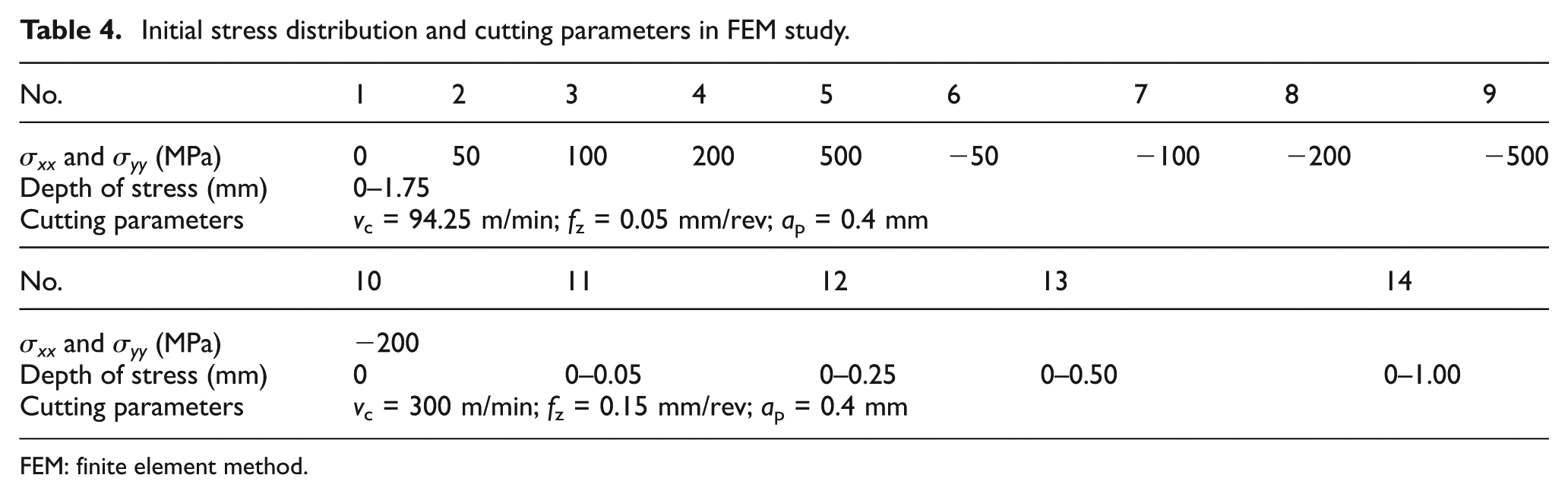
The initial stress distribution was loaded into AdvantEdge by editing a TWS file that defines the stress tensor at representative positions in the workpiece, and the stress distribution can be calculated automatically by the software with interpolation algorithm. As in the analysis of orthogonal cutting, the plane strain condition is assumed, the components of the stress tensor include the normal stress in cutting speed direction (σxx ), the normal stress in feeding direction (σyy ), the normal stress in cutting width direction (σzz ) (perpendicular to the analyzed xOy plane), and the shear stress within xOy plane (τxy ). In simulation Nos. 1–9, different stress values with the same initial stress distribution depth were loaded, while in simulation Nos. 10–14, the compressive initial stresses exist in different depths. The stresses were set to be approximately homogeneous within the initial stress range, and σxx = σyy and τxy = σzz = 0. The designed parameters for each simulation are listed in Table 4.
Initial stress distribution and cutting parameters in FEM study.
FEM: finite element method.
The influence of different initial tensile stress values is shown in Figure 5, and here, only the stress in the main cutting direction, σxx , was analyzed. The simulation No. 1 was used as a reference with zero initial stress. Figure 5(a) shows the stress distribution before and during cutting process. It is clear that the initial tensile stress conceals part of the compressive stress ahead of the tool and strengthens the tensile stress in the area on the reverse extension direction of the shear plane. The stress distribution in the depth direction at 6 mm behind the cutting edge, where the cutting loads are ignorable, is extracted as approximate residual stress distribution, which is shown in Figure 5(b). With the increase of initial tensile stress, the influencing range of compressive stress in surface layer tends to be smaller. Another phenomenon worthy of attention is that the tensile stress distributed in the bulk material (average value below 600 µm from surface) is reduced by about 21%−59%, especially for simulation No. 5, in which the bulk stress decreases from 500 to about 200 MPa.

Influence of different initial tensile stresses on cutting stress distribution: (a) stress distribution in cutting process and (b) approximate residual stress distribution.
Figure 6 shows the influence of different initial compressive stresses on machining stress distribution. The existence of initial compressive stress strengthens the compressive stress ahead of the tool and conceals part of or all the tensile stress on the reverse extension direction of the shear plane, and the influence becomes more and more significant with the increase of initial compressive stress. From Figure 6(b), it is obvious that with the increase of initial compressive stress, the machining-induced residual stress becomes more compressive. The release of initial stress due to machining can also be found in Figure 6(b), with the compressive stress in bulk material reduced by 35%−56%.

Influence of different initial compressive stresses on cutting stress distribution: (a) stress distribution in cutting process and (b) approximate residual stress distribution.
Initial stress distribution also influences the observables such as cutting forces and temperature, as shown in Figure 7. While the initial stress changes from compressive stress to tensile stress, the cutting forces and tool tip temperature tend to decrease, with a changing range of 2%−10%.
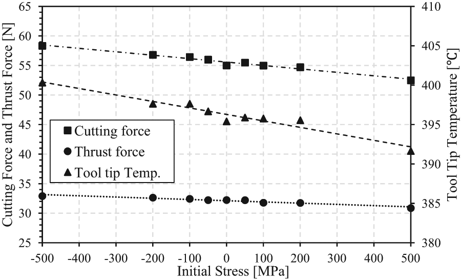
Influence of different initial stress values on cutting forces and tool tip temperature.
As a supplement, the influence of the distribution depth of initial compressive stress (−200 MPa) on cutting stress distribution is analyzed. As shown in Figure 8, with the increase of initial stress existing range, the influence of initial stress becomes more and more significant. When the distribution depth of initial stress is smaller or slightly larger than the uncut chip thickness, the cutting stress distribution is similar to that with zero initial stress, while larger initial stress depth may significantly influence cutting stress distribution.

Influence of initial stress depth on cutting stress distribution.
Discussion
The formation of residual stress can be understood as a process where some impact breaks the initial equilibrium state of the stress field within the workpiece and then builds a new equilibrium state. 3 Here, in metal cutting process, this impact is the coupled thermo-mechanical effects. It is commonly accepted that plastic deformation is one of the principle factors generating the residual stress in machining. 26 A more exact wording would be that the plastic deformation is a key factor influencing the redistribution of the inner stress within workpiece, which may either strengthen or weaken the residual stress.
In the area near and ahead of the cutting edge, the cutting force directly induces large compressive stress. When the sum of initial stress and the machining-induced compressive stress exceeds the yield strength of the material, plastic strain will occur, which provides an approach for initial compressive stress to release. Along the reverse extension direction of the shear plane, shear movement of the workpiece material and the thermal extension of the surface layer result in tensile stress in the bulk material. When large initial tensile stress exists, machining-induced tensile stress strengthens it and may result in plastic deformation when the sum of the two tensile components exceeds the tensile yield strength, and furthermore, the plastic deformation provides an approach for initial tensile stress to release after the machining process. This may explain the decrease of residual stress in bulk material after machining. Yet, although part of the initial stress is released after the machining process due to the plastic deformation, the elastic recovery of the partly released tensile (or compressive) initial stress can still drive the final residual stress distribution to be more tensile (or compressive), compared with that of the zero initial stress state.
On another point of view, the existence of stress field means that there is elastic potential energy stored in the workpiece, the value of which depends on the value and distribution range of the stress. And the equilibrium state of the inner stress is due to the confrontation between the tendency to release the potential energy and the limitations that impede this tendency. During machining process, the rake face of the tool compresses the workpiece material, which confirms to the release of initial tensile stress and goes against the release of initial compressive stress. Thus, the initial tensile stress can help to make the cutting process easier, which means that the cutting forces become smaller and that the external energy consumption related to the temperature rise is reduced, while initial compressive stress makes it harder.
Limitations still exist in this study, and further research may be needed in the following issues. First, the combined method well modeled the strain rate hardening effect in the shear deformation zone at high strain rate in the order of 104 s−1, but as a matter of fact, deformation at lower strain rate also exists in the cutting process. This issue might be solved with a more complicated multilevel constitutive model specifying the effect of strain rate in a wider range and then both the data from SHPB and OCM tests can be used to obtain the strain rate hardening parameters. Second, the initial stress field in this FEM analysis is relatively homogeneous, which is an ideal state used to qualitatively analyze the influence of initial stress. In real machining experiments, due to the self-equilibrating characteristic of the residual stress, there must be tensile and compressive stresses in the workpiece, the sum of which can create zero force and moment resultants within the volume of the structure. 3 Thus, it is difficult to create an experiment condition exactly the same as that in this FEM study. However, the results in this study can be used to explain some experimental observations, such as the change of cutting forces influenced by Liu et al. 13 Third, this study mainly focuses on the influence of initial stress on machining process, and to provide further analysis on superficial residual stress, it is needed to take into account the cooling process of the workpiece after machining. And further theoretical analysis is to be carried out to improve the state-of-the-art theoretical models for machining process.
Conclusion
In this article, a comprehensive FEM simulation on the influence of initial stress on machining process is carried out. A combined method to obtain the parameters in J-C constitutive model which takes advantage of pressure bar tests and orthogonal cutting tests is introduced and proved proper by experiments. With the carefully established FEM model, the influence of initial stress with different values and distribution depths on cutting stress distribution and the value of some observables such as cutting forces and temperature is studied. And the following conclusions can be drawn:
The combined method, which uses the data of pressure bar tests to model strain hardening and thermal softening behavior and utilizes the data of orthogonal cutting tests to model strain rate hardening behavior of material, is a proper way to construct the constitutive model used in machining simulation.
In machining process, the existence of initial tensile stress weakens the compressive stress ahead of the tool and strengthens the tensile stress distribution along the reverse extension direction of the shear plane. With the increase of initial tensile stress, the residual stress within the workpiece becomes more tensile, and the cutting forces and temperature become smaller. Initial compressive stress has opposite effects.
When the distribution depth of initial stress is smaller or slightly larger than the uncut chip thickness, the influence of initial stress is not significant, while larger initial stress depth may significantly influence cutting stress distribution.
The machining process results in the partial release of initial stress in the bulk material.
Footnotes
Academic Editor: Nao-Aki Noda
Declaration of conflicting interests
The authors declare that there is no conflict of interests regarding the publication of this article.
Funding
This research was supported by the Key National Science and Technology Projects of China (grant No. 2013ZX04001-011) and Beijing Natural Science Foundation (grant No. 3141001).