
Abstract
In this research work, a coupled-field finite element model of electro-active paper energy harvester is presented, and the results are verified experimentally. Electro-active paper is a smart form of cellulose coated with electrodes on both sides. A finite element model was developed, and harmonic and transient analyses were performed using a commercial finite element analysis package. Two 80 mm × 50 mm and 100 mm × 50 mm aluminum cantilever benders bonded with electro-active paper were tested to validate the finite element model results. Displacement and voltage generated by the energy harvester at the electrode surfaces were measured. The electro-active paper energy harvesters were excited at their fundamental resonance frequencies by a sinusoidal force located 18 mm from the free end. The voltage obtained from the 80 mm × 50 mm and 100 mm × 50 mm electro-active paper energy harvester finite element model was 3.7 and 7 mV, respectively. Experimental results have shown good agreement with the finite element model. The direct piezoelectric effect of electro-active paper shows potential for a cellulose-based eco-friendly energy harvester.
Introduction
The recent surge in microscale devices has encouraged researchers to harvest energy from ambient vibration using piezoelectric materials. 1 Among most experimental 2 and mathematical models, a piezoelectric cantilever beam is excited harmonically at its first resonance frequency to obtain an acceptable voltage output. 3 The electrical output from these energy harvesting devices can be used to power micro-electromechanical system (MEMS) devices and wireless sensors. However, extracting power output from the vibration energy for pervasive and ubiquitous devices and structural health monitoring sensors is realistic; there are some practical limitations, in terms of frequency bandwidth, ambient vibration amplitude, and properties of piezoelectric materials. 4 Energy harvesting devices that operate at higher frequencies have been reported, but no such ambient vibration is available for those frequencies. Piezoceramics are known to be the best smart materials, in terms of electromechanical coupling, but their efficiency in harsh vibration is limited, due to their brittle nature. 5 This encourages developing novel materials that are flexible and exhibit a piezoelectric effect. Surface electromyography (sEMG)–based joint force control, 6 multi-fingered dexterous hand for grasping manipulation, 7 and adaptive vibration control of string and flexible marine riser are the other smart applications already developed.8–10
Electro-active polymers have received relatively little attention, due to the small number of available materials and their limited actuation capability. The large displacement response of electro-active polymer has changed their potential capability. They are lightweight, inexpensive, and fracture tolerant. 11 Due to the wide range of ambient vibration sources and brittle nature of lead zirconium titanate (PZT), other piezoelectric materials, such as macro-fiber composites, 2 ZnO piezoelectric thin films, 12 piezopolymer polyvinylidene fluoride (PVDF), 13 and electro-active polymer, 14 have been investigated for actuators and energy scavenging devices. The use of eco-friendly cellulose-based electro-active paper (EAPap) to scavenge energy from ambient vibration showed encouraging results.15,16 These materials show reasonable piezoelectricity and are normally used in applications where efficiency is not the primary concern.
Cellulose is biodegradable, inexpensive, biocompatible, easy to manufacture, and ultra-light in weight. It contains all the characteristics of a smart material 17 and has been successfully employed in piezo speakers, 18 vibration sensors 19 and actuators, beam vibration control, 20 and artificial muscle application. 21 It can also be used in MEMSs and biomimetic sensor/actuators. EAPap is a smart form of cellulose, in which electrodes are deposited on both sides of cellulose film. The weak piezoelectricity of cellulose was reported very early. 22 The actuation mechanism of EAPap when an external field is applied is a combination of the retained ion migration and piezoelectric effect. The piezoelectricity of EAPap is reversible; it is instigated from the dipolar orientation and monoclinic structure of cellulose. The converse piezoelectric effect of cellulose with conducting polymer as an electrode has been studied, 23 and the effect of thickness, relative humidity, and temperature on the performance of actuators was also presented. 24 Multi-walled carbon nanotube (MWNT)–mixed cellulose EAPap has enhanced the performance of the actuator. 25 When a stress is applied on piezoelectric material, induced current is generated on the surface of electrodes. This phenomenon is known as the direct piezoelectric effect. The direct piezoelectric effect of EAPap was very similar to some of the piezopolymer PVDF films. 26 The piezoelectricity of EAPap was sensitive to material orientation and drawing ratio and can be enhanced by the wet drawing method 27 and by mechanical stretching during the regeneration process when an external field is applied. 28 Mechanical properties29–32 of EAPap are sensitive to relative humidity and temperature; creep, viscous, and elastic behaviors have been reported, along with blocked force measurement, using a custom-built force transducer. 33 To enhance the capabilities of EAPap, future possibilities and challenges were addressed to extend cellulose-based smart material applications to micro-insect robots, micro-flying objects, biosensors, and flexible electrical displays. 34
From the open literature, it is evident that EAPap piezoelectricity can be used to harvest power from ambient vibration. It has all the characteristics of smart materials and can withstand high-amplitude vibration. In this article, a finite element model (FEM) of EAPap energy harvester is presented. Harmonic and transient analyses are performed and validated with the experimental results. The FEM shows good agreement with the experimental results.
FE analysis
Cellulose-based EAPap utilizes the piezoelectric effect to generate a voltage output in response to an applied mechanical stress. Most of the known piezoelectric materials behave linearly at a low mechanical stress and electric field. The coupled electromechanical constitutive equations for linear piezoelectric material are as follows 35

where
After the application of the variational principle and FE discretization, the coupled FE matrix equation is
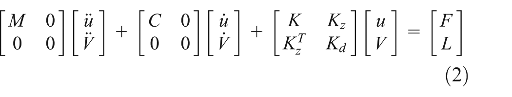
where M is the structural mass matrix and C is the damping matrix used in harmonic and transient analyses. K represents the structure stiffness, Kd is the dielectric conductivity, and Kz is the piezoelectric coupling matrix. F is the structural load vector and L is the electrical load vector.
For the FEM of an EAPap energy harvester, the commercial FE analysis (FEA) package ANSYS was used. SOLID45 element is used for aluminum and SOLID5 for the piezoelectric EAPap patch. The SOLID45 element has eight nodes and three translational degrees of freedom (DOFs), while the SOLID5 element contains three translational DOFs and one electric potential DOF. The EAPap was modeled by a SOLID5 element that can be used to model the thermal, electric, piezoelectric, and structural fields, with coupling effects. The geometric and material properties used in FEA of the energy harvester are given in Tables 1 and 2, respectively.
Geometric parameters for the EAPap energy harvester.

Material properties of the EAPap energy harvester.

EAPap is a complex anisotropic material, and its mechanical and piezoelectric properties are very sensitive to temperature and relative humidity. Using the properties described in Table 2, the piezoelectric constant matrix, relative permittivity matrix, and elastic compliance matrix were developed. Harmonic and transient analyses were performed using the commercially available FEA package ANSYS. The DOFs of the cantilever bender were constrained at one end, and a time-dependent input force was applied to vibrate the structure at the first bending resonance frequency. The input force was applied at a distance of 18 mm from the free end. Displacement was measured at the same point where the sinusoidal force was acting, and the electrical potential generated was measured on the top surface of the EAPap. A meshed FEM of the EAPap energy harvester is shown in Figure 1. All the nodes at the interface between the aluminum bender and EAPap were put at zero electric potential. The voltage was measured at the top surface of the EAPap. The results obtained from the FEM were validated with the experimental results. The adhesive thickness was ignored because the adhesive layer between piezoelectric EAPap and substrate aluminum was very thin.

Meshed FEM of the EAPap energy harvester.
Experimental setup and procedure
To validate the accuracy of the presented FEM, it is imperative to experimentally demonstrate the behavior of the EAPap energy scavenger. The EAPap transducer was fabricated by cutting a 40 mm × 40 mm cellulose film. The detailed method to fabricate EAPap is described in the literature.27,36 A fabricated specimen of cellulose-based EAPap is shown in Figure 2(a). The cellulose film was coated with 40 mm × 40 mm aluminum electrodes on both top and bottom surfaces. The thickness of electrodes was 100 nm. Figure 2(b) shows a schematic diagram of the top view of the EH100 energy harvester.
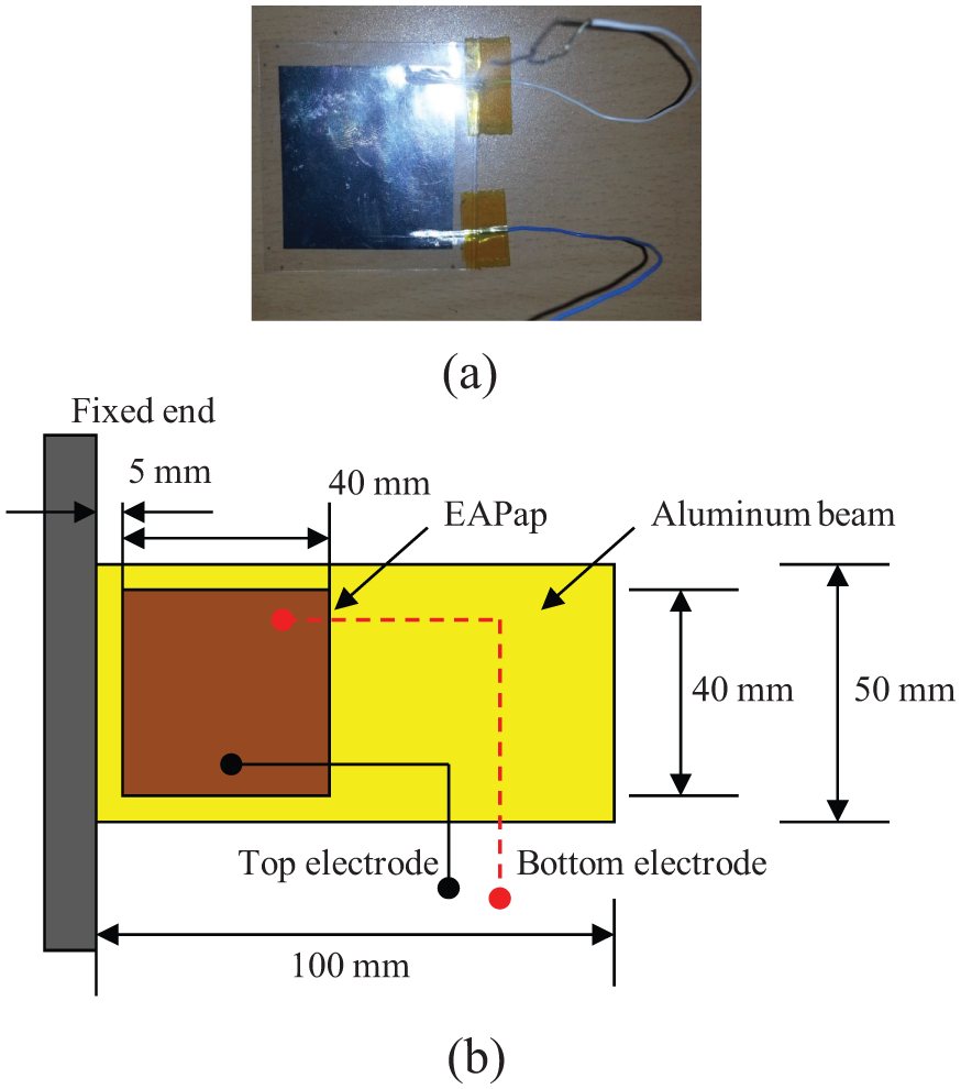
(a) Fabricated EAPap specimen and (b) top view of the EH100 energy harvester.
The fabricated specimens were tested using the conventional energy harvesting setup. The experimental setup for energy scavenging consists of a function generator (Agilent Technologies), power amplifier (Brüel & Kjær, Korea), laser displacement sensor (Keyence), shaker (The modal shop, Inc.), LabShop PULSE analyzer (Brüel & Kjær, Korea), force transducer (Brüel & Kjær, Korea), and a computer. An aluminum 6063-T5 cantilever structure was used as the substrate, and the piezoelectric EAPap fabricated sample was attached at a distance of 5 mm from the clamped end. The material properties of aluminum are described in Table 2.
A schematic diagram of the experimental setup employed to validate the FEA results is depicted in Figure 3. The EAPap transducer was actuated by a shaker, using a sinusoidal input signal produced by a function generator. The signal was amplified with the help of a power amplifier. The input vibration was monitored with a force transducer attached at the top of the shaker. The sensitivity of the force transducer (Model No. 8230-001, Brüel & Kjær, Korea) was 22.6 mV/N. The displacement was measured using a laser displacement sensor, at a distance of 18 mm from the free end. The EAPap-bonded aluminum cantilever bender was excited using the described experimental setup, and the generated output signal was analyzed by personal computer.

A schematic diagram of the experimental apparatus.
Results and discussion
The consistency in the values of the composite beam geometry, location of EAPap, and applied load on the cantilever substrate allows a fair comparison of the results from the FEA and experiments. In order to find the natural frequencies of the EAPap energy harvesters, a harmonic analysis was performed on the developed FEM. To compare the FEM results, an impact test was performed on the EAPap energy harvester, and the frequency response functions (FRFs) were obtained. In case of the experimental results, transfer function between voltage output and input force was obtained over a frequency range of 10–800 Hz by hitting the cantilever bender with an impact hammer. The voltage output was taken as the numerator in the transfer function and impact force became the denominator. The magnitude is presented as Volts/Newton which is converted to decibels for better resolution of the FRFs. A conventional relationship was used to convert the FRF from Volts/Newton to decibels, dB = 20 × log (magnitude). FEM FRF of output voltage to input force was measured by harmonic analysis over a range of frequency 10–800 Hz and compared with the experimental results. The output voltage of piezoelectric EAPap was measured from the output data of SOLID5 in response to the input excitation. A comparison of experimental and FEM FRFs of output voltage to input force for EH80 energy harvester is shown in Figure 4.

Comparison of FE model and experimental FRFs of EH80.
From these results, it can be observed that the FEM and experimental results predict the first natural frequency of the bender with good accuracy. However, a notable difference was observed at higher natural frequencies between the FEA results and the experimental results. The first bending natural frequency of EH80 was 120 Hz. In frequency response analysis, the twisting mode of the bender was also prominent.
A similar experimental technique as described above was used to establish a voltage to force FRF for EAPap energy harvester EH100. Harmonic analysis was carried out on the developed FEM to get the FRF over a frequency range 10–600 Hz. In response to the input force, output voltage was measured from SOLID5 element of the FEM. Fundamental natural frequency measured using the FEM harmonic analysis shows good agreement with the experimental results, but there is prominent difference at the higher bending and twisting mode natural frequencies. A comparison of FEM FRFs measurements and experimental voltage to force FRFs of EH100 is plotted as depicted in Figure 5.

Comparison of FE model and experimental FRFs of EH100.
The results obtained from the harmonic analysis were used to set up the time-dependent load in transient analysis. FRFs reveal that the first bending natural frequency is 120 Hz for EH80 and 80 Hz for EH100. The dynamic load at the first resonance frequency applied on the FEM shows the strong dependency of the direct piezoelectric effect on the frequency. The dynamic load was measured with the help of the energy harvesting experimental setup. The sinusoidal signal was generated by function generator and was used to vibrate the EAPap-deposited aluminum cantilever. A force transducer was employed at the top of the shaker to measure the dynamic force. The sensitivity of the force transducer is 22.6 mV/N. The input force was recorded by using a pulse analyzer for both the EAPap energy harvesters, EH80 and EH100. A plot of experimentally measured force used to excite the EAPap cantilever is presented in Figure 6.

Input force measured by the force transducer: (a) EH 80 and (b) EH100.
In order to validate the FEM, displacement and voltage output were measured experimentally for both the EH80 and EH100 energy harvesting benders, when excited by a sinusoidal force at a distance of 18 mm from the free end. The FEM displacement for the EH80 was 2.7 μm. Using the energy harvesting setup, the EH80 was excited, and both displacement and voltage output were measured. The displacement measured by the laser displacement sensor positioned at 18 mm from the free end was 2.5 μm. FEM and the experimentally measured displacement for EH80 is shown in Figure 7. Transient analysis was performed on the FEM to find the voltage generated on the electrode surfaces of the EAPap. The voltage measured from the FEM for EH80 was 3.7 mV. By applying a sinusoidal force at the first resonance frequency of EH80, the generated voltage on the EAPap was measured, using a pulse analyzer and personal computer. The peak voltage output measured using the energy harvesting setup on the EAPap was 3.6 mV. Figure 8 depicts the relationships between the FEA and the experimental results obtained for voltage output. It was observed that the FEM shows good agreement with the experimental results, when the EH80 bender was excited by a sinusoidal force at the fundamental mode of vibration.
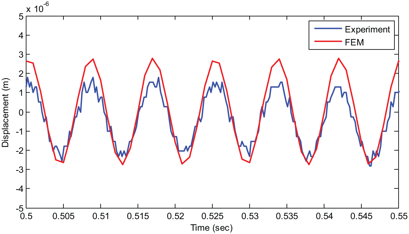
Displacement measured at 18 mm from the free end for EH80.

Voltage output produced by EH80 when excited by a sinusoidal force at 18 mm from the free end.
The FEM results were also compared for the EH100 EAPap energy harvesting bender. From the FEM, the displacement was measured at a distance of 82 mm from the clamped end. A laser displacement sensor was used to measure the displacement experimentally for EH100. The displacement measured from the FEM and experiment was 8 and 8.2 μm, respectively. The results obtained for the displacement from FEM and experiment are compared in Figure 9. Only the steady state response was plotted, although the analysis performed on the EH100 was transient analysis. It can be seen from Figure 8 that the displacement output obtained by FEM and experiment agrees reasonably well. The open circuit voltage output for EH100 was measured on the top electrode. The bottom electrode was grounded. The open circuit voltage measured from the FEM for EH100 was 7 mV, when EH100 was excited at its first resonance frequency, 80 Hz. The sinusoidal force was acting at a distance of 82 mm from the clamped end. The voltage output steady state response of EH100 is plotted in Figure 10. It was observed that the voltage output measured by the experimental setup correlates with FEM reasonably well. The value of the output voltage measured experimentally was 6 mV.
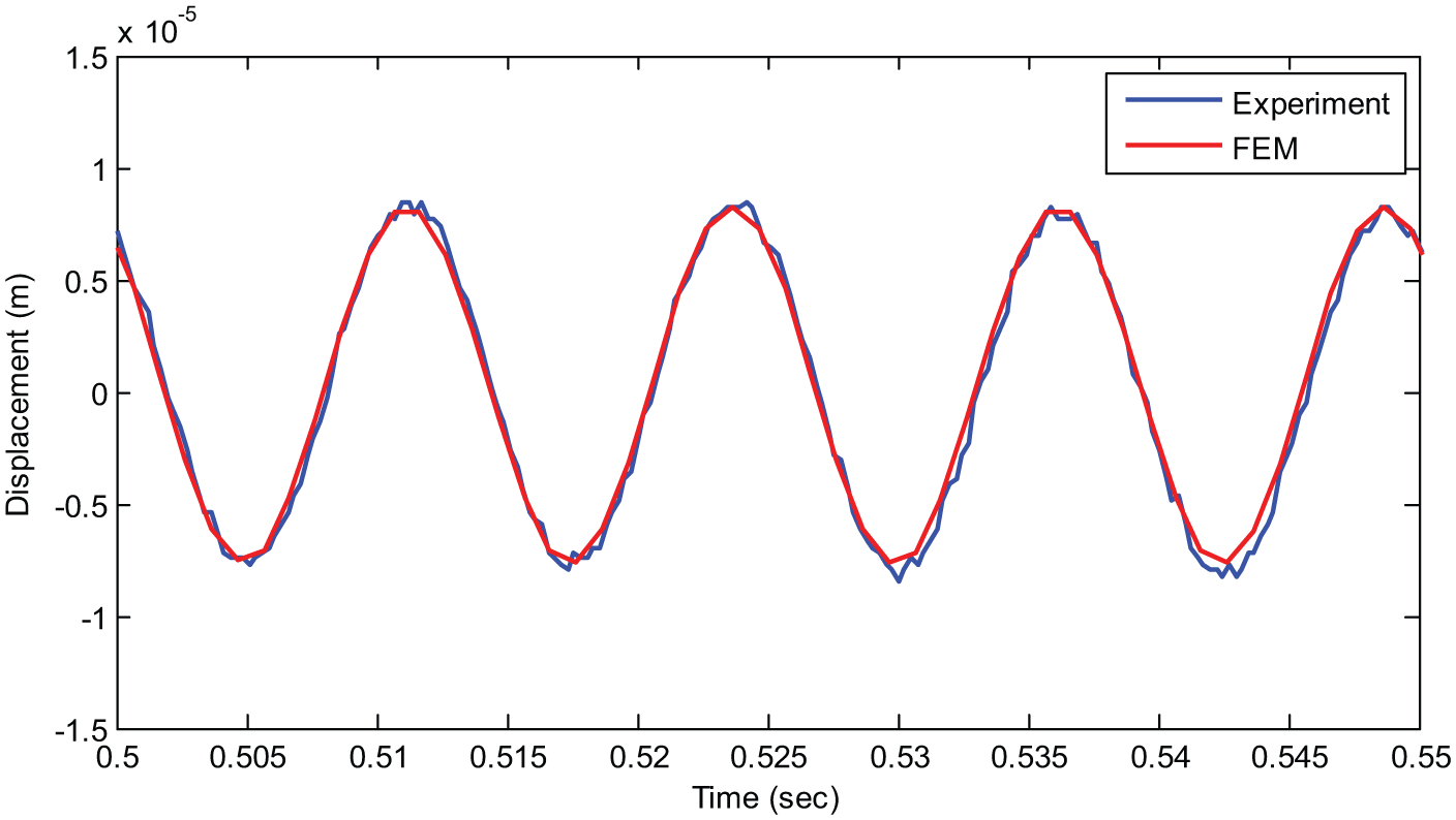
Displacement measured at 18 mm from the free end for EH100.

Voltage output produced by EH100 when excited by a sinusoidal force at 18 mm from the free end.
Conclusion
This article proposed an EAPap energy harvester subjected to sinusoidal excitation near the tip of a cantilever aluminum substrate. An FE coupled-field analysis was performed to simulate the mechanical and electrical behaviors of the energy harvester. Fabricated specimens were also tested experimentally to validate the FEM. The harvester was excited at its first resonance frequency by a sinusoidal force, and the piezoelectric effect of the EAPap generates a voltage on the electrodes. The cantilever 80 mm × 50 mm FEM bonded with a 40 mm × 40 mm EAPap patch generated a voltage output of 3.7 mV, which shows good agreement with the experimental value of 3.6 mV. The FEM was also validated by a 100 mm × 50 mm cantilever bonded with a 40 mm × 40 mm EAPap patch. The FEM peak voltage was 7 mV, which correlates reasonably well with the experimental results of 6 mV. The displacement output for EH100 from the FE and experimental results was 8 and 8.2 μm, respectively. It is concluded that the cellulose EAPap piezoelectric effect can be used in energy harvesting applications. Although the output voltage from the EAPap energy harvester is relatively low, as compared to other piezoelectric materials, it has many advantages, in terms of flexibility and being naturally available and eco-friendly.
Future studies are required to improve the energy harvesting characteristic of cellulose-based EAPap; in particular, the dielectric constants and electromechanical coupling need to be tailored. Improved piezoelectric and mechanical properties will lead to the generation of acceptable voltage and corresponding output power.
Footnotes
Declaration of conflicting interests
The authors declare that there is no conflict of interests regarding the publication of this article.
Funding
This work was supported by the Technology Innovation Program (10048305, Launching Plug-in Digital Analysis Framework for Modular system Design) funded by the Ministry of Trade, Industry & Energy (MI, Korea).