
Abstract
Complex electromechanical system is usually composed of multiple components from different domains, including mechanical, electronic, hydraulic, control, and so on. Modeling and simulation for electromechanical system on a unified platform is one of the research hotspots in system engineering at present. It is also the development trend of the design for complex electromechanical system. The unified modeling techniques and tools based on Modelica language provide a satisfactory solution. To meet with the requirements of collaborative modeling, simulation, and parallel computing for complex electromechanical systems based on Modelica, a general web-based modeling and simulation prototype environment, namely, WebMWorks, is designed and implemented. Based on the rich Internet application technologies, an interactive graphic user interface for modeling and post-processing on web browser was implemented; with the collaborative design module, the environment supports top-down, concurrent modeling and team cooperation; additionally, service-oriented architecture–based architecture was applied to supply compiling and solving services which run on cloud-like servers, so the environment can manage and dispatch large-scale simulation tasks in parallel on multiple computing servers simultaneously. An engineering application about pure electric vehicle is tested on WebMWorks. The results of simulation and parametric experiment demonstrate that the tested web-based environment can effectively shorten the design cycle of the complex electromechanical system.
Keywords
Introduction
Complex electromechanical systems are always composed of many parts (e.g. mechanical components, electronic components, hydraulic components, etc.), so the modeling and simulation oriented for multiple domains are becoming more and more important. However, because of the limit of single domain simulation tool, it is a formidable task to treat these multiple domains systems with a single tool. Besides, for the feature of multiple domains, specialists from various specialties are needed to collaboratively design the complex electromechanical systems. Then it raises the question, how to overcome the problems of collaborative design, concurrent design and team cooperation? Even if the final simulation models of complex electromechanical systems have been constructed, how to finish the large-scale simulation tasks in a quick and simple way, especially for the computerized design of experiments? Fortunately, a standardized language, Modelica, can solve part of these problems.
The uniform modeling and simulation technology based on Modelica has been improved during last decades. Modelica is an object-oriented and equation-based language, 1 and has been widely applied in many areas because it is easy and convenient to express complex models, multi-domain electromechanical systems. 2 Up to now, there exist many tools for standalone commercial modeling and simulation based on Modelica: Dymola, 3 SimulationX, 4 AMESim, 5 MapleSim, 6 MathModelica, 7 MWorks, 8 etc. And there are also some free Modelica-based tools that are currently available like OpenModelica, 9 JModelica, 10 and Modelicac. 11 However, there exist several shortcomings: first, the standalone platform cannot support collaborative and concurrent modeling, which becomes more and more crucial for modeling of multi-domain electromechanical system. For the feature of complexity and multidiscipline, the system-level modeling of multi-domain electromechanical systems based on Modelica is difficult to be accomplished by an individual or an individual enterprise. So it is necessary to study the collaborative modeling based on Modelica. Second, modeling components and simulation components of standalone platforms are bundled compactly so that the simulation solving is dependent on the same modeling computer. If the user wants to run a complex simulation or multiple simulation tasks at the same time, the process must be time-consuming because simulations are run in the same local machine. Finally, standalone platforms do not support parallel computing so that they are inefficient to execute some centralized computing tasks such as parametric experiments.12,13
To overcome the shortcomings of standalone tools, we studied and implemented a general web-based modeling and simulation environment for multi-domain electromechanical systems. Web-based simulation (WBS) is the integration of web and simulation technology. 14 Compared to traditional standalone simulation tools, WBS environment has many advantages such as wide usability, cross-platform capability, maintainability, and upgradeability. Moreover, it can conveniently realize sharing of model library, collaborative modeling, separated services, and parallel computing. The area of WBS has been grown since the mid-1990s. 15 As for collaborative modeling, communication and interaction is one of the essential factors to achieve a successful simulation project. 16 It is feasible to develop environment with coherent web-based support for collaborative model development,17,18 in which people can communicate with each other from different places to develop the same simulation model over the web. This approach may result in a reduction in model development cost and time especially for a complex multi-domain electromechanical system.
WBS systems can usually be split into two categories: 14 local modeling, local visualization, and simulation; local modeling and visualization, remote simulation. The former means that the modeling, simulation engine, and visualization components are installed seamlessly by the client to the user’s local computer. Thus, the graphical interface and the simulation engine coexist in the same environment, which make sure that the server could act as a central distribution point and a database to/for the simulation. 19 In the latter mode, simulation engines are located and executed remotely on the server-side.20,21 These engines are accessed through modeling portals on browser sides. This approach can be considered (as) a job request on a batch processing system. Parameters are submitted to the simulation engine through the web server, and results are returned to the user once the simulation has finished running. Cloud simulation 22 is the frontier and tends of WBS which comes from grid simulation. 23 It can be defined as “a new, generalized, and extensible simulation framework that enables seamless modeling, simulation, and experimentation of emerging cloud-computing infrastructures and application services.” 22
Related research works of WBS are virtual experiment and programming languages teaching. In Duarte, 24 a web simulation environment UN-Virtual Lab was presented, on which the virtual experiment can be defined by the administrator, and the users can modify the experiment parameters to view the results in browser. In Eva-lena Lengquist et al., 25 a web version of the DrModelica was implemented. In Torabzadeh-Tari et al., 26 a web-based teaching environment called OMWeb was presented. Students can send their exercises to compile and calculate on the server that contains many OpenModelica Compiler (OMC) wrappers, and teachers can view the results. In Shi et al., 27 a web-based visual modeling environment was developed for electrical engineering experiment. And computational methods applied to Modelica simulation models in a web-based framework was also studied. 13 Users can complete the experiment through connecting the custom experimental components, and the results of the experiment can be obtained after the simulation. However, all the studies presented were based on the specific purpose and lacked some features that are actually needed in industry and research, such as a general web-based visual graphical editor. A web platform, called Proteus, 28 has been developed by a team in Nanyang Technological University. Proteus was designed for education and academic research, where students, educators, and academic researchers can easily create and share their computer models of electromechanical systems based on Modelica. It came with a web-based, graphical modeling, and simulation tool called Proteus GWT that was implemented by Google Web Toolkit. With the development of Modelica technology and wide reuse of models within the Modelica community, Modelica Standard Library (MSL) or users’ model library will become huge in the future. How to deal with this situation? Johansson et al. 29 tried to address this problem by providing the Modelica community with a Modelica DB database for storing models and services for querying this database to perform a wide range of model engineering tasks in a scalable fashion.
Although some platforms were designed just for teaching or experimenting, there still exist three problems to solve: (1) How to provide a timing graphical modeling interface for convenient modeling just like the standalone platform? (2) How to support collaborative modeling for complex, multi-level electromechanical system by several designers in various specialties? (3) How to finish large-scale of simulation tasks at the server-end quickly? To solve these problems, a general web-based modeling and simulation prototype environment is designed and implemented.
The remainder of this article is organized as follows. In Section “Research background on the WebMWorks,” the web-based environment WebMWorks is introduced. In Section “Key technologies for electromechanical system design,” several key technologies for electromechanical system design are described. In Section “Engineering application,” an engineering application about pure electric vehicle is tested based on WebMWorks. Finally, the conclusions of this work are given in Section “Conclusion remarks.”
Research background on the WebMWorks
Deployed on cloud-computing platform, the WebMWorks (http://www.modelicabase.com/) provides an online visual modeling, simulation, and knowledge sharing environment. Through the Internet, users can get the services to design the complex electromechanical systems at a low cost whenever from wherever.
Architecture and deployment
To build a reusable and loosely coupled architecture with independent interfaces, WebMWorks adopts the idea of service-oriented architecture (SOA) which is implemented by using Windows Communication Foundation (WCF) technology. WCF is a unified programming model provided by Microsoft for building service-oriented applications. With WCF, the core functions of the system is wrapped as a service and called by the internal or external program. The environment based on a layered architecture is shown in Figure 1.
Presentation Layer.
The Presentation Layer at browser is a web portal for modeling and post-processing. The Presentation layer contains a SilverLight 30 plug-in which is a RIA technology released by Microsoft, with the capabilities of cross-browser and cross-platform. It can be used to provide delicate graphical interface for frequent interactions.
Service Layer.
This layer consists of five independent servers: Web Server, Library Server, Modeling Server, Compilation Distributing Server, and Simulation Distributing Server. Here, the WCF technology is adopted to package the functions of the program on the server, and the Presentation Layer can get the variety of services from the Service Layer.
The Web Server is used to host the client portal, containing the web pages and SilverLight plug-in package. It also handles various requests from the client and provides the services of user management and permission management through accessing the database at the Data Storage Layer.
The Library Server is responsible for model management and library access. It receives requests from the client to get information of the library, to add/update/delete models in the library, or to change the structure of the library through accessing the File Storage and Database at the Data Storage Layer.
The Modeling Server receives requests from the browser while modeling, including parameters modifying and graph-text transforming request. It provides the corresponding services through accessing the compilation component in the Compilation Distributing Server at the same layer.
The Compilation Distributing Server receives the compiling requests from the client at the Presentation Layer or from the Modeling Server at the same layer. It was implemented via a compilation queue, which was realized by using Microsoft Message Queuing. When a compilation request is received, the Compilation Distributing Server will put it into the compilation queue. Then, the server makes a balanced distribution of the requests to the nodes of Compiling Cluster at the Computation Layer.
The Simulation Distributing Server receives simulation requests from the client. It provides the solving services for the Presentation Layer. Similarly, a simulation queue is designed at this server. When a simulation request is received, this server will put it into the simulation queue. And the server also makes a balanced distribution of the requests to the nodes of Solving Cluster at the Computation Layer.
Computation Layer.
The layer consists of two computing clusters: Compiling Cluster and Solving Cluster. In each cluster, there are several nodes that are responsible for compilation tasks and simulation tasks, respectively. When the Compilation Distributing Server and the Simulation Distributing Server receive the requests from outside, tasks in the compilation queue and the simulation queue will be distributed to the Compiling Cluster and Solving Cluster, respectively, where the tasks will be executed on the corresponding nodes in parallel.
Data storage layer.
This layer consists of a Database Server and a File Storage Server. Database Server manages the information of the users and the metadata of Modelica models. The metadata contains the relationship among models and the properties of the Modelica models, such as type, name, path, description, and owner. File storage server is used to store mo files of the models according to the storage rules of Modelica models. It also stores SVG files (Scalable Vector Graphics file, the graphical files for Icon view), result files of the compilation and simulation, and some other inter mediate files.

System architecture of the WebMWorks.
From the architecture mentioned above, we can give the system deployment or topological structure as Figure 2 shows. As shown in Figure 2, both Compiling Cluster and Solving Cluster are a set of cloud-like servers. The node number in the cluster can be deployed in line with the actual requirements such as the number of the browsers. The nodes of the cluster can be installed in one computer or different computers. They are distributed by the distributing server to do compilation or simulation tasks and return the results to the distributing server. Then the distributing server returns the results to the caller.

System deployment of the WebMWorks.
System workflow
The WebMWorks provides variety of services for the user remotely through network. Using these services, the user can log into the system, create and modify an electromechanical system model, compile and simulate the model, and fetch and visualize the simulation results. The system workflow consists of the following processes in order:
System initialization.
After all, the servers are started up, the database server loads the system database at first, then the Compiler Nodes in the Compiling Cluster load MSL from the file storage to memory for compiling services.
User environment initialization.
After successful login, the user will be assigned the appropriate permissions. At the same time, the Compiler Nodes in the Compiling Cluster load individual library belonging to the user from the file storage to memory. Then, the browser interface loads the libraries (MSL, personal library, and public library) through calling the services provided by the Library Server. The user should select a Modelica version when logging.
Modeling.
In the modeling page, the user can create an electromechanical system model in the interactive environment, as in the traditional Modelica IDE, such as Dymola, MWorks, or OMEdit. After the user creates a new model in the memory at client-end, it is copied to the Compiler Nodes when executing the compilation. And it will be stored into the database and file storage when the user saves the model.
Not only the modeling task can be done in the graphical mode, but also it can be done with text mode. With the graph-text transformation service from the Compilation Distributing Server, one can also switch among different views to modify the model. In fact, the information required during the modeling, such as the icon/diagram/text/references, parameters, and properties of the components, can be all achieved by calling the services that are provided by the Compilation Distributing Server.
Compiling the model.
Modeling process needs compilation services indirectly. Besides, the user can do the checking model command directly. The compilation process can be divided into the following three steps.
First, the client submits the diagram of the current model in XML format to the Compilation Distributing Server and calls the graph-text transformation service provided by some compiler node. The diagram will be resolved to mo text in the node server, and the mo text will be saved/updated to the database and file storage server. Second, the client calls the compilation services to send the compilation request into the compilation queue. Finally, the Compiler Processor gets the compilation data from the queue, compiles the mo file of the model, and generates/updates document object model (DOM) and equations solving sequence (ESS), then returns the compilation results to the caller at last.
Simulating the model.
The request of the simulation from the client will be put into the simulation queue in the Simulation Distributing Server. Then the SolveProcessor in one Solver Node gets the simulation data from the queue and calls the MWSolver to solve the ESS, to generate and to return the result of the simulation.
Post-processing.
In the post-processing page, the user can monitor the process of simulation through the services provided by the system. When the simulation is completed, the resulting data can be packed into XML and sent to the client and displayed on the page.
Key technologies for electromechanical system design
To shorten the design cycle of the complex electromechanical system and save design costs, the web-based environment WebMWorks adopts the methods of collaborative modeling and parallel computing. A brief discussion of the key technologies is presented in the following sections.
Collaborative modeling
WebMWorks provides a good support for collaborative modeling which is important to the complex electromechanical system. Because an electromechanical system may consist of various components involving multiple domains, a group of members from various specialties is in need to model the system. Collaborative modeling means that there is a general manager who is responsible for the top layer design of the electromechanical system, and there are several designers who are responsible for design of the components in the second layer or sub-managers who are responsible for design of the sub-systems; in the same manner, there are some designers of next-sub-managers under the sub-managers who are responsible for design of the components in the third layer. Usually, the designing (or modeling) process belongs to top-down designing. The designers under the same (sub) manager can do their work concurrently and collaboratively.
Take a typical multi-domain electromechanical system, for example, as shown in Figure 3(a), a group of designers are designing a robot, which has a mechanics component, six axis controller components (just with different parameters), and a pathPlanning component. The diagram of the axis controller is shown in Figure 3(b).

Collaborative modeling for a complex electromechanical system (a) top layer of the robot and (b) the diagram of the axis controller.
As shown in Figure 3(c), the designer A0 is the chief designer of the robot, who is responsible for constructing the skeleton of the system and defining and manipulating the data bus. The designers A1, A2, and A3 are design managers appointed by A0, and they are responsible for designing the “pathPlanning” component model, the “axis controller” component model, and the “mechanics” component model, respectively. On the third layer, the A11 is appointed by A1 to design the “pathToAxis” component model in the “pathPlanning” component model; A21 and A22 is appointed by A2 to design the “controller” and the “motor” component model, respectively.
The collaborative modeling includes two processes: top-down designing and bottom-up refining. The design project is launched by a chief designer, who creates some new “blank” components according to the system architecture at first. Meanwhile, these blank components are appointed to some specific users. After a blank component is created, the following two events have happened: a new model has been created at the compiler node and can be seen at the browser and the user of the new created model is set according to the appointment of the chief designer. After the new blank components were created, the chief designer begins to define the data bus and create connections among these components. Although the bus is also blank at the beginning, it will be refined gradually with the designing progress.
Recursively, the user (designer) of a new blank component model can also create some new blank components and appoint them to other users, and build connections through data bus. This top-down designing process can be illustrated in Figure 4(a).

Two processes of collaborative modeling (a) top-down designing and (b) bottom-up refining.
In the WebMWorks, only the owner of a model can edit the model, but other users can open and show it. After the top-down designing process is finished, the appointed users begin to design their component models. The managers will then update the data bus and monitor the modeling progress: the icons of the components become considerate instead of the original blank rectangle. A component model becomes fully intact only after its child-components models and recursive child-components models have been completed. That means that only after all the components models have been completed, the refining process of the top-level model is finished. This process is shown in Figure 4(b).
Parallel computing
Compilation and simulation for an electromechanical system based on Modelica are invariably time-consuming. Under the WebMWorks, users can submit their tasks to the WebMWorks, and they will be handled in parallel. The compilation tasks are submitted to the Compilation Distributing Server, where the tasks are distributed to Compiler Nodes in balance; while the simulation tasks are submitted to the Simulation Distributing Server, where they are distributed to the Solver Nodes in balance in the same way.
Computerized design of experiment is the common application of parallel computing. In the WebMWorks, we can do single parametric experiments for an electromechanical model. That means, we can select a parameter and a response variable from the model, assign different values for the parameter, and then simulate the model for multiple times to analyze the relationship between the response variable and the parameter.
In the WebMWorks, a simple strategy for load balance on the distributing server (Compilation Distribution Server and Simulation Distribution Server) is realized. The server fetches one task from the task queue and distributes it to the executing node according to the number of the running tasks on the node. That means, the node who has the least running tasks will receive the new task. If some of the nodes have the same least running tasks, the current task will be distributed to one of them randomly.
Engineering application
Pure electric vehicle
“Multi-domain modeling and simulation for pure electric vehicle (PEV)” is a part of the government major project which is sponsored by Dongguan, China. This task aims at building an electromechanical model for PEV and doing some experiments to analyze the performances of the vehicle. Because the PEV is a typical multi-domain electromechanical system involving mechanical system, electronic system and control system, and so on, it needs several professionals to design the model. In addition, the PEV is a so complex system that it should take long time to simulate it, let alone the parametric experiments. Consequently, WebMWorks will be chosen to fulfill this task, and a scenario of working with the environment will be introduced.
The appearance of real PEV is demonstrated in Figure 5. It has a battery, a motor, a driver, a controller, a chassis, and other components. The PEV is built based on the experiments of the real PEV. Up to now, we have finished modeling for the PEV and have done some performance simulation including propulsion, economy, manipulation, and ride-comfort. The collaborative modeling process and some results of simulation and parametric experiment will be introduced in the following section.

Pure electric vehicle: the appearance of PEV (left) and the structure of PEV (right).
Collaborative modeling
A group of designers (registered users of the system) participated in this modeling task. Among them, A0 is the chief designer and is responsible for the top-level design. A0 created an electromechanical model PEV.mo and added some new blank components, including driver, display, controller, battery, motor, and chassis. Then A1, A2, A3, A4, A5, and A6 were appointed to design the corresponding component model, respectively, shown in Figure 6(a). For the chassis is a complex component model, A6 appointed A61, A62, A63, and A64 to design sub-component models: drive line, brake, vehicle (body and tires), and steering, as demonstrated in Figure 6(b). Specifically, the designers worked at the same time in several places to create the components (or sub-component models) of PEV, and this way saves a whole lot of time for all developers. In MWorks (http://www.china-modelica.com), the time of loading the MSL and users’ libraries takes about 5 s, and it takes only 6 s to load these libraries on the WebMWorks. The user can create, modify, and delete models when designing the PEV model and can switch between the different views to modify the model.

Collaborative modeling for PEV (a) top-level model architecture of the PEV and (b) top-level final model of PEV.
Component models description
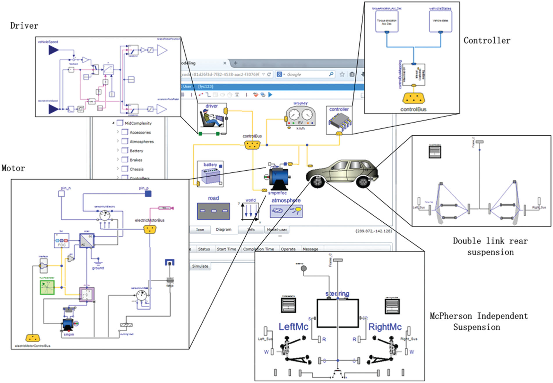
The final PEV model and the components of vehicle are shown in Figure 7. All of these components have standardized bus interfaces which can be used to connect with other components seamlessly and make these components more reusable and interchangeable. The modeling principle of main components of vehicle will be described in the following sections.
Motel component.
To facilitate analysis of steady-state and dynamic performance of permanent magnet synchronous (PM) motor, the d–q coordinate mathematical model is used. And the voltage equations of PM motor in the steady-state are expressed as

and the flux-linkage equations are express as

where ud and uq are d- and q-axis stator voltages; id and iq are d- and q-axis stator currents; Rd, Rq, Ld, and Lq are d- and q-axis stator resistance and inductance, respectively;
The torque T of PM in the d–q coordinate is expressed as

where pn is pole pairs.
The kinematics equation of PM is expressed as

where
Battery component.
The charging and discharging processes of battery are affected by many factors and are complicated and non-linear processes. So the effect of internal heating and chemical for battery state of charge state (SOC) and the voltage and current should be considered when designing the battery model. In a variety of modeling methods, the equivalent circuit modeling method for battery modeling can effectively simulate the properties and dynamic character of battery.
The PEGV equivalent circuit model, as shown in Figure 8, is proposed by the US Department of Energy. Uoc, Ro, Rp, Cp, and Cb are ideal voltage source, ohmic resistance, polarization resistance, polarization capacitance, and capacitance of battery, respectively.
Besides, the above five parameters are changed with different SOC, and the change process of SOC is needed to be considered when designing the battery model
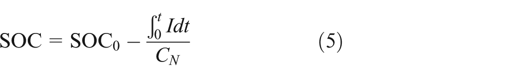
where CN is the rated capacity of battery.
Driver component.
The driver component is a proportional integral derivative (PID) controller and controls the speed of the vehicle. As the PID is a liner controller and e(t) is error between output y(t) and given value r(t), the control variable u(t) is linear combination of proportional, integral and differential of e(t)

where
Chassis component.
The suspension system of chassis component is composed of McPherson front independent suspension and double link rear suspension. The McPherson independent suspension is shown in Figure 9. B0, B1, B2, B3, B4, and B5 are car body, lower control arm, steering knuckle, wheel, shock absorber, and tie-rod, respectively. h1 is revolute joint, and h2, h4, and h6 are sphere joints.
The final pure electric vehicle model.

PNGV equivalent circuit model.

McPherson independent suspension.
The front suspension is constructed according to the basic structure of McPherson independent suspension, just like the rear suspension. Both of these two suspensions use the three-dimensional (3D) data capturing from PEV model to determine the position relationship among various parts in suspension.
Simulation and results
To test the performances of the PEV, different drive-cycles from the Driver component can be chosen to simulate the PEV. In our research, the driver follows the Environmental Protection Agency (EPA) Urban Dynamometer Driving Schedule (UDDS) to drive the vehicle, as shown in Figure 10. The simulation results, comparison of desired speed and real speed, SOC change curve, and distance curve, are demonstrated in Figure 11.

The UDDS drive-cycle.
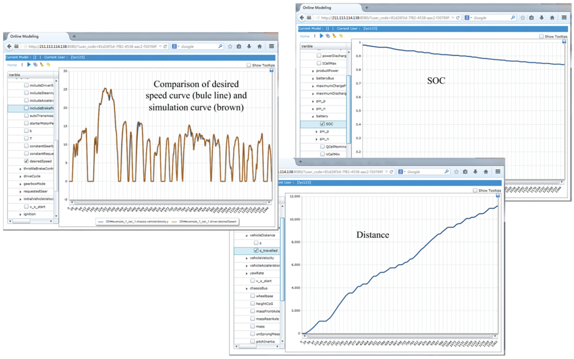
Simulation results of the PEV with given drive-cycle.
As can be seen from the Figure 11, the simulation curve of vehicle speed is almost the same as desired speed. The simulation curve of vehicle speed reaches the maximum longitude speed 91.8 Km/h (25.5 m/s) or so at the time of 240.9 s. And the SOC curve of PEV drops along with the vehicle moving, and the travel distance increases over time. It is noted that all the simulation curves obtained from WebMWorks are the same as those from MWorks.
Parametric experiments
The parametric experiments like parameter sweeping were also considered in the design process of PEV. It can help people to analyze the relationship among factors. In WebMWorks, the “Sweep Parameter” module can be implemented, which can do the simulations of the parameter experiments on the parallel Solving Cluster.
The setup of “Sweep Parameter” module is demonstrated in Figure 12. As seen from the Figure 12, the example_4-2 (the test model name) is selected as the main analyzing model, and the ratio of the “driveLine” component is selected as the sweeping parameter, the maximum travel distance as the response variable. The value of sweeping parameter indicates the number of simulation for model. For example, the EquiDistantGird (3.1, 4.5, 5) shows the range of variable ratio is 3.1 to 4.5, and the range is subdivided into five times, which means the PEV model needs to be simulated for five times. In our tests, we set the value of n to 14. In the parallel computation, the Solver Nodes are added as needed. To test the parallel computing ability of WebMWorks, the numbers of Solver Nodes are 1–6.

“Sweep parameter” in WebMWorks.
The speedup ratio aindex and parallel efficiency η of parallel computation are calculated as follows
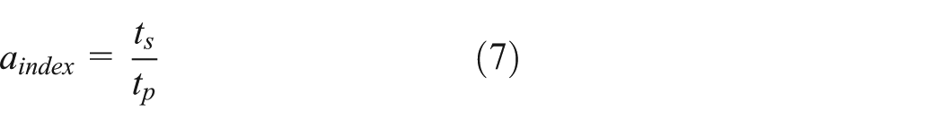
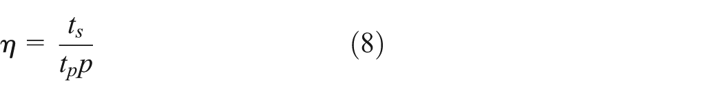
where p is the number of the Solver Nodes, ts is the simulation time for all the parametric experiments using a single Solver Node, and tp is the simulation time using p Solver Nodes.
A total of six tests were performed on the system, and one of the experiment results with six Solver Nodes were demonstrated in Figure 13. As observed from Figure 13, the travel distance changes with different ratios. The correlations of Solver Nodes with ts, aindex, and η are shown in Figure 14. As more Solver Nodes were added to the system, the simulation time and the parallel efficiency decreased gradually, and the speedup ratio increased. However, as influenced by the network condition, the computer performance of Solver Nodes, the correlations of Solver Nodes with ts, aindex, and η had fluctuating results.

Results of parametric experiments.
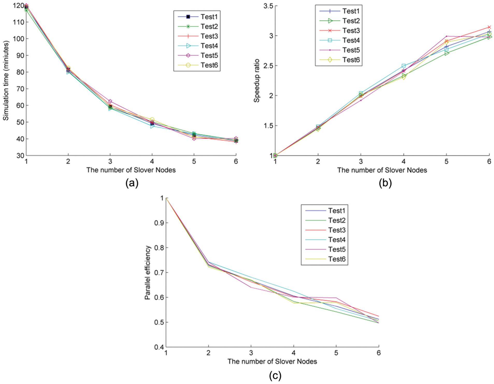
The correlations of Solver Nodes with simulation time, speedup ratio, and parallel efficiency. (a) The relationship between Solver Nodes and simulation time, (b) the relationship between Solver Nodes and speedup ratio, and (c) the relationship between Solver Nodes and parallel efficiency.
Furthermore, WebMWorks takes about 37 min to finish all these simulations with six Solver Nodes. Compared with WebMWorks, however, MWorks takes about 114 min to run parametric experiments, almost four times longer than WebMWorks.
This application fully demonstrated the superiority in parallel computing for the platform. The designers satisfied with the WebMWorks and are impressed by the higher efficiency of development compared with MWorks they used.
Concluding remarks
As the electromechanical systems become increasingly complicated, collaborative modeling and parallel computing are needed in the design cycle. To meet with these capabilities, a general web-based modeling and simulation prototype environment, namely, WebMWorks, is designed and implemented. The architecture, implementation, and key technologies of the WebMWorks were described, and the advantages of WebMWorks can be summarized as the following three aspects:
Web-based. WebMWorks is a web-based modeling and simulation environment, and can be easily accessed at any browser. And users can model, simulate, or show the simulation results for the same model on different website. Especially for a complex electromechanical system model, simulation task can be submitted to the powerful Solver Nodes.
Collaborative modeling. WebMWorks provides a function to create a new blank component model and allow the user to appoint a designer to design the component model. This can support collaborative modeling for a complex electromechanical system as the engineering application illustrated.
Parallel computing. The compilation and simulation tasks submitted from different users can be distributed in WebMWorks. And especially multiple simulations arising from parametric experiments can be distributed efficiently on the Solving Cluster.
As the platform is a prototype system, it is currently undergoing a series of tests, and user can visit the platform on the Internet. Besides, the platform system will be improved gradually in the following areas in the future:
Enforce the capability of data transport, especially compression and decompression of the transporting data;
Improve safety of the model storage;
Add the function of 3D visualization in post-processing.
Footnotes
Acknowledgements
The authors have declared that no competing interests exist, and the authors would like to express our acknowledgement to Professor Zuomin Dong from University of Victoria, Canada, and Associate Professor Xiong Hui-Yuan from Sun Yat-sen University, China, who gave us many help, some advices and good comments for this work.
Declaration of conflicting interests
The authors declare that there is no conflict of interest.
Funding
This work was supported by National 863 project (no. 2013AA041301) and the National Natural Science Foundation of China (nos. 51175198, 51275182, and 51375186).