
Abstract
In this article, 20 kW ocean thermal energy conversion with a vapor–vapor ejector is newly proposed. As a vapor–vapor ejector is installed in the system, the pressure difference between the turbine inlet and outlet increases. Therefore, the amount of the working fluid required for the total turbine work of 20 kW is less than when no vapor–vapor ejector is installed. Therefore, installing a vapor–vapor ejector in the system decreases the evaporation capacity and the pump work. The performance analysis considered the outlet pressure of the high-stage turbine, the mass flow ratio of the working fluid at the outlet of a separator just after the high-stage turbine, and the nozzle diameters of the vapor–vapor ejector. As the outlet pressure of high-stage turbine becomes lower, the turbine gross power of high-stage turbine and system efficiency increase although lower outlet pressure of high-stage turbine results in lower ejector performance. Similarly, in terms of mass flow ratio, the highest system efficiency was shown at mass flow ratio of 0.4 at the outlet of a separator just after the high-stage turbine. On the other hand, the performance of the ejector at mass flow ratio of 0.5 at the outlet of a separator was largest. When the nozzle diameters of the vapor–vapor ejector are properly designed, the vapor–vapor ejector shows the highest performance. After the optimization of the operation parameters, system efficiency of the proposed ocean thermal energy conversion power cycle was 2.47%, relatively 15% higher than that of the basic ocean thermal energy conversion power cycle (2.2%).
Introduction
With the steady rise in the usage of fossil energy, ocean thermal energy conversion (OTEC), a renewable-energy system, is increasingly being regarded as the solution to global warming and environmental pollution. The OTEC power cycle is a system that produces electricity from the generator of a turbine with a temperature difference of 21 °C–24 °C between the surface seawater (the upper temperature level) and the deep seawater (the lower temperature level). Since the temperature and pressure difference between high level and low level is too small, the system efficiency of the OTEC power cycle is relatively lower (about 2%) than those of other kinds of renewable-energy systems such as waterpower generation (about 80%−90%) and solar heat generation (about 10%−15%). Thus, various researches with the aim of improving its system efficiency are underway worldwide. The previous researches for improving the system efficiency of the OTEC power cycle are discussed below.
Soto and Vergara 1 researched on the work conditions and system size depending on the efficiency of the system adopting waste heat from power plants and reported that the turbine gross power of the system increases by 1.3% when the system utilizes the waste heat from power plants. Yamada et al. 2 reported that the system efficiency of the OTEC power cycle can be increased 1.5-fold if the temperature of the surface seawater flowing into an evaporator with a solar collector will be increased or by providing more superheat to a working fluid that evaporates in an evaporator. Yoon et al.3–5 suggested a high-efficiency OTEC power system using a regenerator and a cooler and conducted a performance analysis to confirm the system’s high efficiency. By placing a regenerator at the evaporator inlet, the evaporation capacity was decreased, increasing the system efficiency. A performance analysis of subcritical OTEC power cycle with various working fluids was conducted. Additionally, an ejector was placed at the condenser inlet, and an initial research about the optimization process was done by adjusting the mass flow ratio of a working fluid at the outlet of a separator just after the high-stage turbine and the diameters of the ejector.
Zhang et al. 6 explained different Kalina systems and their different applications. Kalina cycle has been diversified by applying different components or using different heat sources. Low- or high-temperature geothermal energy, heat from industrial wastewater, coal, and other solid fuels are those of good examples. Additionally, to confirm the efficiency of this cycle, energy analysis was conducted, the revised cycle was compared with the basic Kalina cycle, and the cycle was explained.
Li et al.7,8 set an ejector at the condenser inlet of the Kalina cycle and researched on the effect of the ejector on the system efficiency. Turbine gross power increased compared with the basic OTEC power cycle. The change in the turbine gross power based on the placement of an ejector between the turbine outlet and the condenser inlet of the supercritical organic Rankine cycle (ORC) was reviewed. The turbine gross power was highest at the supercritical ORC with an ejector.
Huang and Chang 9 came up with an ORC system with an ejector and provided basic data for the performance of the ejector and for the interrelation between the nozzle area ratio of the ejector and the mass flow ratio flowing into the ejector.
In the previous studies mentioned above, an ejector was applied to improve the system efficiency of the OTEC power cycle. In this study, to improve the system efficiency of the OTEC power cycle, a vapor–vapor ejector was installed at the condenser inlet of the system. In addition, performance analysis was conducted for the optimization of this power system, and the factors in the optimization are as follows. First, the outlet pressure of the high-stage turbine was adjusted, and then the mass flow ratio at separator 1 (states 4 and 6) and the diameters of the vapor–vapor ejector nozzle were controlled to determine the optimal performance conditions and output.
OTEC power cycle and theoretical concept of the vapor–vapor ejector
Basic OTEC cycle
Figure 1 shows schematics of the basic OTEC cycle. Basic OTEC cycle has four main components, consisting of an evaporator, a turbine, a condenser, and a refrigerant pump. The liquid refrigerant in the evaporator is heated and vaporized by surface seawater at 26 °C. This vapor refrigerant flows into the turbine where its enthalpy is converted into power, and then vapor refrigerant in the condenser is cooled and condensed by releasing heat to deep seawater at 5 °C. The pump is used to circulate and pressurize the refrigerant in the OTEC power cycle continuously. The high-pressure liquid refrigerant flows into the evaporator to complete the cycle. So, as long as temperature difference between the surface and deep seawater is large enough, the cycle will continue to operate and generate power.

Schematics of the basic OTEC.
Proposed OTEC cycle applying a vapor–vapor ejector
Figure 2 shows the schematic of the high-efficiency OTEC power cycle with a vapor–vapor ejector.

Schematics of the OTEC power cycle using a vapor–vapor ejector.
As regards the flow of the working fluid of the OTEC power cycle with a vapor–vapor ejector, first, the working fluid that passed the evaporator flows into the high-stage turbine with the states of high temperature and high pressure, and then expands into the liquid–vapor state. To separate the expanded liquid and vapor, separator 1 was installed at the outlet of the high-stage turbine. The liquid separated from separator 1 flows into pump 1 and is then pressurized up to the evaporation pressure. The vapor is then divided into two: that which flows into the low-stage turbine and that which goes to the motive part of the vapor–vapor ejector. The high-temperature vapor that passed through the low-stage turbine flows into separator 2 after becoming low-temperature liquid–vapor. At this point, the liquid from the separator is pressurized up to the evaporation pressure as it flows into pump 2; meanwhile, the vapor flows into the suction part of the vapor–vapor ejector. The vapor from a suction nozzle is compressed, and the one from a motive nozzle is expanded inside the ejector and is then spurted at the discharge part of the ejector. Thereafter, this vapor is condensed at the condenser and then flows into pump 3. Each liquid, which is pressurized by pumps 1–3 up to the evaporation pressure, is mixed at the inlet of the evaporator.
Figure 3 shows the stage points of the OTEC power cycle with a vapor–vapor ejector on a P–h diagram. In Figure 3, condensation pressure is defined as state points 10 and 11; by utilizing a vapor–vapor ejector, the outlet pressure of the low-stage turbine is decompressed up to state point 7, which is lower than the condensation pressure. Thus, the gross power of the low-stage turbine increases with the application of a vapor–vapor ejector when fixed amount of working fluid circulates. When the system is set to produce 20 kW, the required amount of working fluid is reduced by increased pressure difference of turbine inlet and outlet. Therefore, installing a vapor–vapor ejector decreases evaporation capacity, condensation capacity, pump work, and system size.

P–h diagram of the proposed OTEC power cycle using a vapor–vapor ejector.
In short, the OTEC power cycle proposed in this article is summarized as a cycle that increases the turbine gross power by adopting multi-stage turbines, multi-stage pumps, and a vapor–vapor ejector.
Theoretical concept of the vapor–vapor ejector
The internal structure of the vapor–vapor ejector proposed in this article is shown in Figure 4. This ejector mainly consists of a motive part, a suction part, and a discharge part. The working fluid from state 4 in Figure 1 is fed to the motive part and passes through the nozzle. At this point, following Bernoulli’s theorem, the velocity of the motive working fluid increases, and its pressure decreases. Here, the working fluid from state 8 in Figure 2, which is the suction flow, is inhaled by the motive working fluid and then flows inside. The inhaled suction working fluid is mixed with the motive working fluid that passed through the nozzle, as shown in the constant-area section of Figure 4. The mixed working fluid is emitted through the discharge part. Performance analysis of the OTEC power cycle with a vapor–vapor ejector was done using Aspentech HYSYS. 10 The correlation deciding the discharge pressure of the ejector is shown below


Schematic diagram of the vapor–vapor ejector.
According to equation (1), the pressure of the discharge part is determined by the diameters of the nozzles of the discharge part and by the mass flow and velocity of the suction, discharge, and motive parts. Thus, the proper mass flow ratio of the motive flow and suction flow (states 4 and 6), velocity in the ejector, and diameter ratio of motive part, suction part, and discharge part are very important factors deciding the performance of the vapor–vapor ejector.
State equation and simulation method
State equation
A state equation is required to analyze the performance of OTEC power cycle applying a vapor–vapor ejector using HYSYS. Peng–Robinson equation of equation (2) that involves interrelation of components is used to calculate phase balance of compounds. 11
In addition, the formula yielding the system efficiency is shown as equation (6)


Simulation method
The simulation conditions are shown in Table 1. Regarding the working conditions, the inlet and outlet temperatures of each surface seawater and deep seawater are the most important factor in this study, and these are considered not to be changed since these are fixed values by the surroundings. The evaporator inlet pressure of the cycle, which is suitable for the conditions shown in Table 1, is 1536 kPa, and its condenser inlet pressure is 1196 kPa. The outlet pressure of the high-stage turbine was adjusted between these two values. Similarly, the pump power was also decided by evaporator inlet pressure and condenser inlet pressure. After setting the conditions in Table 1, the following variables were changed: outlet pressure of high-stage turbine (state 3) from 1200 to 1500 kPa, mass flow ratio at separator 1 outlet (state 4) from 0.2 to 0.8, and the diameters of the motive nozzle, suction nozzle, and discharge nozzle. The mass flow at the outlet of separator 1 is divided into two parts: the part that flows into the motive part of the vapor–vapor ejector (states 4) and the part that goes to the low-stage turbine (states 6).
Simulation conditions of the basic and proposed OTEC power cycle using the vapor–vapor ejector.

OTEC: ocean thermal energy conversion; LMTD: logarithmic mean temperature difference.
The simulation conditions and the method of basic OTEC cycle are the same as the proposed OTEC cycle, shown in Table 1.
Results and discussion
Outlet pressure of the high-stage turbine
The heat flow transferring from the heat source to working fluid in the evaporator, pump power, system efficiency, and ejector performance was analyzed by adjusting the outlet pressure of the high-stage turbine. Figure 5 presents the system efficiency, pump work, and evaporation capacity depending on the outlet pressure of the high-stage turbine. The system efficiency showed the highest value when the pressure was 1200 kPa. On the other hand, the evaporation capacity and pump work were not changed by the outlet pressure. Thus, the most proper outlet pressure of the high-stage turbine is 1200 kPa.
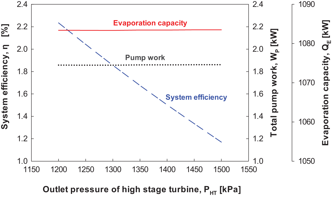
Evaporation capacity, pump work, and system efficiency with respect to the outlet pressure of the high-stage turbine.
Figure 6 shows the effect of the outlet pressure on the internal pressure and performance of the ejector. Pressure recovery defined as equation (10) is used to show the performance of the ejector

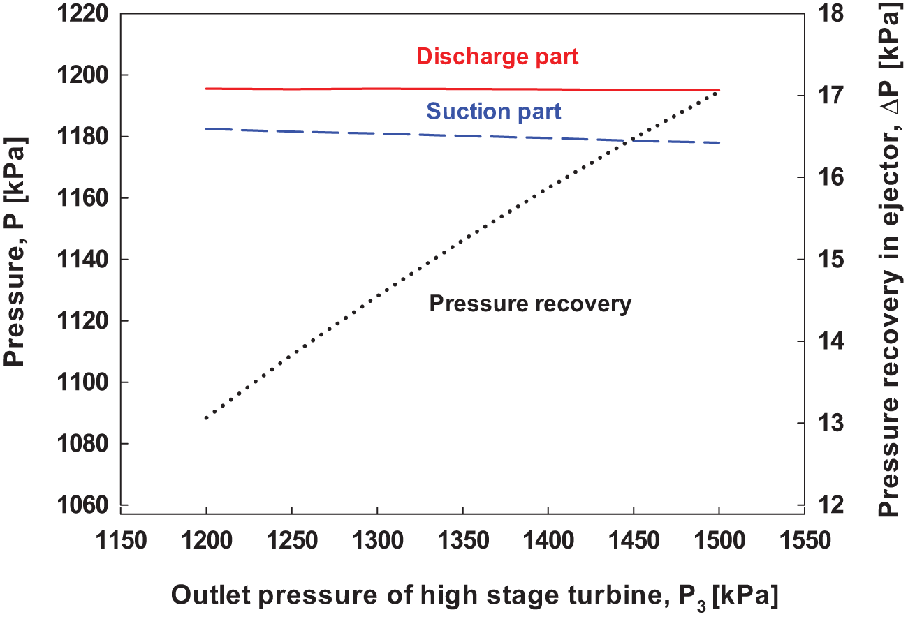
Pressure recovery with respect to the outlet pressure of the high-stage turbine.
ΔP in equation (10) is the result of the subtraction of the suction pressure from the discharge pressure of the ejector. The bigger the pressure difference between them, the bigger the pressure recovery that occurs from the vapor–vapor ejector, which signifies the excellent performance of the ejector. As can be seen in Figure 6, the optimized outlet pressure of the high-stage turbine is 1500 kPa. In other words, when the pressure of the high-stage turbine is 1200 kPa, the performance of the vapor–vapor ejector shows the lowest performance, and at the pressure of 1500 kPa, it presents the highest value.
Thus, from the aforementioned results shown in Figures 5 and 6, the optimized outlet pressure of the high-stage turbine in the aspect of system efficiency, and that in the aspect of the performance of the vapor–vapor ejector, is different. However, system efficiency is the most important result in this study, while the ejector is only a part of the total system although it still takes an important role of improving system efficiency. Even if the performance of the ejector is low, the outlet pressure of high-stage turbine with the highest system efficiency should be selected. Therefore, the optimized high-stage turbine outlet pressure is 1200 kPa.
Mass flow ratio at the outlet of separator 1 (states 4 and 6)
As shown in Figure 1, the working fluid that passed through the low-stage turbine flows into the suction part of the vapor–vapor ejector. As it undergoes expansion in the low-stage turbine, liquid is partly formed. The amount of this liquid, however, is less than about 2%. Therefore, much of the working fluid flows into the suction part of the ejector as vapor.
Figure 7 presents the evaporation capacity, total pump work, and system efficiency depending on the mass flow ratio at the outlet of separator 1 (states 4 and 6), and the system efficiency is highest when the mass flow ratio at state 4 is 0.4.

Evaporation capacity, pump work, and system efficiency with respect to the mass flow ratio of state 4 at the outlet of separator 1.
Figure 8 shows the results of the performance analysis of the ejector depending on the mass flow ratio. From equation (10), when the mass flow ratio of state 4 was 0.5, pressure recovery was the highest and performance of the ejector was the best. In short, the system efficiency was the highest when the mass flow ratio of state 4 (i.e. the inlet of the low-stage turbine) is 0.4. Additionally, in terms of the performance of the ejector, the pressure recovery was highest when the ratio was 0.5. There was a difference between the optimized ratio for the highest efficiency and that for the performance of the ejector. Similar to the case described in section “Outlet pressure of the high-stage turbine,” system efficiency is the most important result in the cycle. Although the performance of the ejector is low, the mass flow ratio with the highest efficiency should be selected for the optimization.

Pressure drop with respect to the mass flow ratio of state 4 at the outlet of separator 1.
Diameters of the vapor–vapor ejector nozzle
The effect of diameters of the vapor–vapor ejector nozzles on the performance of the cycle was analyzed. Table 2 shows the diameters of the nozzles of the vapor–vapor ejector. Five diameter size cases are proposed with respect to the mass flow ratio at the outlet of separator 1, and all the diameters of the vapor–vapor ejector are reduced by 10 mm from cases 1 to 5.
Proposed diameters of the ejector.

Figure 9 shows the evaporation capacity, pump work, and system efficiency depending on the diameters of the vapor–vapor ejector. As the diameters of the nozzles were decreased from cases 1 to 5, the system efficiency drastically increased, and the pump power and evaporation capacity decreased. As all the diameters of the ejector are reduced, the performance of the ejector is improved. Therefore, the required amount of the working fluid to produce set turbine gross power is decreased. As a result of it, evaporation capacity and pump work are decreased, and it causes an increase in the system efficiency together with the improved performance of the ejector.
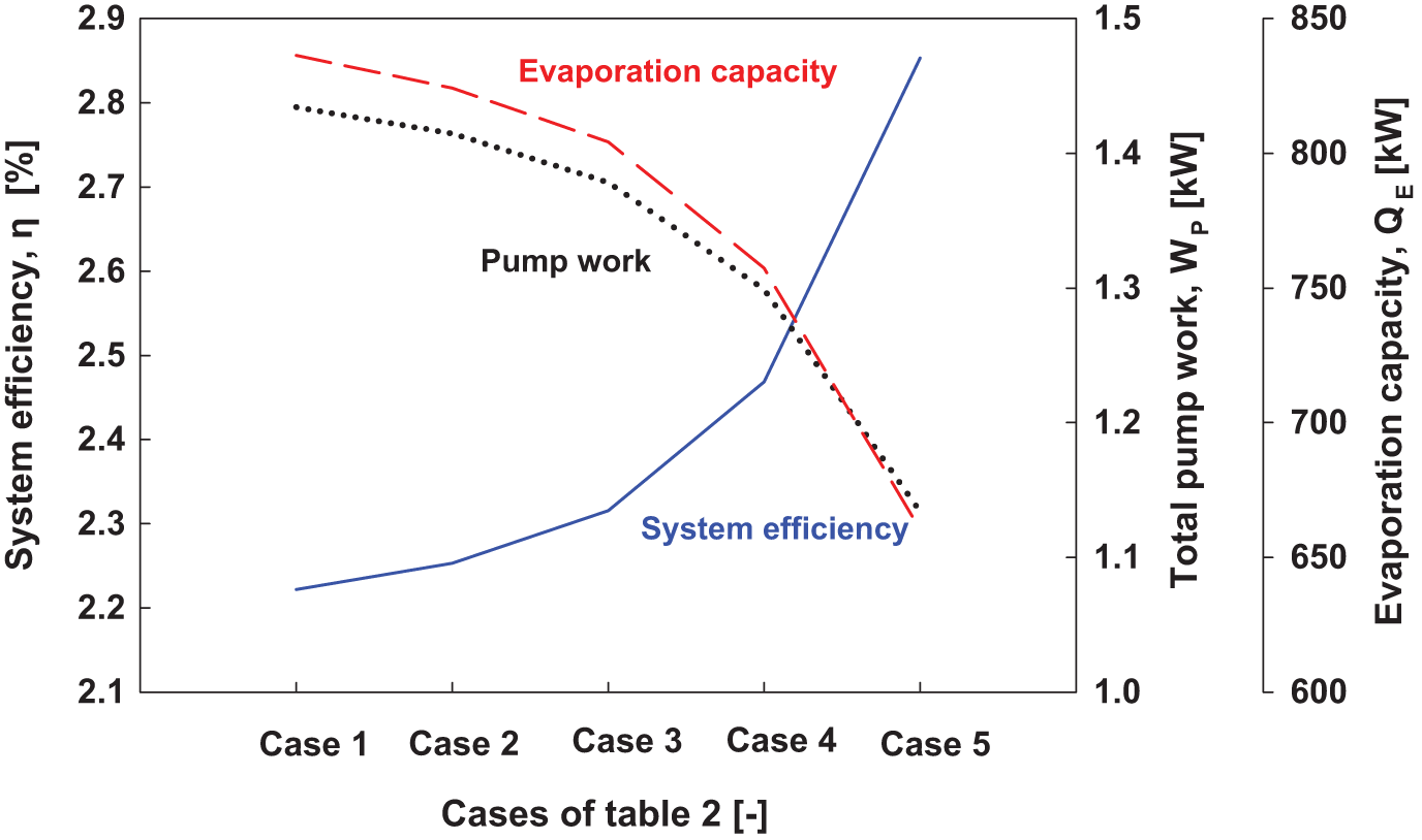
Evaporation capacity, pump work, and system efficiency with respect to the nozzle diameters of the ejector.
Figure 10 shows the performance of the vapor–vapor ejector. The pressure recovery increased from cases 1 to 5 of the designed nozzle diameters. In this cycle, discharge pressure is fixed to condensation pressure, decided by the temperature of deep seawater. Following equation (1), Ps decreases as Vs and Vm decrease. Here, the velocity of the flow is the subordinated factor of diameter of the nozzle. Therefore, the results show that suction pressure decreases as the nozzle diameter decreases.

Pressure recovery of the ejector with respect to the nozzle diameters of the ejector.
Figure 11 shows the flow velocity of the motive, suction, and discharge part depending on the diameters of the nozzle of each part. The desirable velocity range of the mass flow, which goes into the vapor–vapor ejector, was set at 30–60 m/s considering the shockwave that might occur due to the supersonic vapor. The results with respect to the diameters of the nozzles, according to Table 2, are as follows.

Optimized nozzle diameters of the ejector with respect to the permissible flow velocity.
In case 4, when the nozzle diameters of the motive, suction, and discharge part were 35, 45, and 40 mm, respectively, the flow velocity at these three parts was within the suitable range of 30–60 m/s.
In conclusion, the system efficiency increases and the performance of the ejector is improved by reducing the diameters of each nozzle. The optimized diameters of the nozzle, however, in the aspects of system efficiency and suitable flow velocity are 35, 45, and 40 mm for motive part, suction part, and discharge part, respectively.
Optimization result of proposed OTEC cycle with a vapor–vapor ejector
From the process described in sections “Outlet pressure of the high-stage turbine,”“Mass flow ratio at the outlet of separator 1 (states 4 and 6),” and “Diameters of the vapor–vapor ejector nozzle,” the optimized working conditions were decided as shown in Table 3. The system efficiency of the OTEC power cycle with a vapor–vapor ejector can be improved compared to the basic OTEC power cycle by optimizing the outlet pressure of high-stage turbine, the diameters of the vapor–vapor ejector nozzles, and the mass flow ratio at the outlet of separator 1 (states 4 and 6). Especially, varying the diameters of the nozzles causes the largest enhancement of the system efficiency compared to controlling the other factors proposed by this study.
Optimized conditions of the proposed OTEC power cycle using the vapor–vapor ejector.

Conclusion
This study evaluated an idea of dividing mass flow at a separator outlet and adding a vapor–vapor ejector at the condenser inlet to improve system efficiency of an OTEC power cycle. The process flow of the proposed system was analyzed to optimize system efficiency. The optimized condition is shown in Table 3. The system efficiency of the proposed system was determined to be 2.47%, which is relatively 15% higher than that of the basic OTEC power cycle (2.2%).
By using the vapor–vapor ejector, it can be seen that the low-stage turbine gross power will be decreased because the amount of the working fluid flowing into the low-stage turbine is reduced. Considering the performance of the vapor–vapor ejector, however, the ejector drops the pressure at the outlet of the low-stage turbine to a point lower than the condensation pressure. This results in an increase in the gross power of the low-stage turbine and the system efficiency.
Footnotes
Appendix 1
Academic Editor: Haitao Yu
Declaration of conflicting interests
The authors declare that there is no conflict of interest.
Funding
This work was financially supported by the R&D project of ‘Development of Desalination Plant using Ocean Thermal Energy’ supported by the Korea Research Institute of Ships & Ocean Engineering.