
Abstract
This work uses numerical methods to investigate the hydrodynamic forces that act on a turbine ring gate during emergency shutdown. Accurately predicting the hydrodynamic forces on such gates is important because the forces constitute a design criterion of ring gates, especially in the case of the downward-pulling hydrodynamic force, which directly affects the opening or closing of the gate. In this article, we use Fluent, which is a computational fluid dynamics code, to simulate the flow patterns around the ring gate and to calculate the hydrodynamic forces on the gate. We numerically simulate the three-dimensional unsteady turbulence over the entire flow passage of the turbine. The numerical results show that the hydrodynamic forces are induced mainly by flow acceleration under the bottom surface of the ring gate. When the ring gate is at 90% closing position, the downward-pulling hydrodynamic force is maximal; near the completely closed position, the hydrodynamic force is more sensitive to the position of the ring gate. This investigation of the hydrodynamic forces that act on the ring gates provides the theoretical basis for determining the operational capacity and the optimal design of ring gates.
Introduction
A turbine ring gate is a new type of inlet gate that works as a combined emergency and guard gate for closing and opening and whose structure differs from that of conventional inlet gates (butterfly and ball gates). 1 The turbine ring gate is installed directly between the guide vanes and stay vanes in a Francis turbine flow channel and serves to prevent water from flowing from the spiral casing into the guide vanes. 2 By means of vertical movement of the gate body, turbine ring gates promptly cut off water and are, therefore, extensively applied in high-head hydropower plant.1–3 However, in the emergency shutdown process, the partial closing of the ring gate causes hydrodynamic forces on the gate body due to velocity variations with the gate closing and the unstable flow past the gate lip. 4 Designing and manufacturing ring gates with optimum performance requires that these hydrodynamic forces be known. These forces include the water-column force that acts on the top surface of the gate, the downward suction force or upholding force that acts on the bottom surface of the gate, and the hydrodynamic friction forces that act on the internal and external surfaces of the ring gate. All these forces are important to consider for determining the capacity of the ring gate when open and when closed. If these forces are not properly considered, the ring gate may not open or close. In addition, these variable hydrodynamic forces induce highly complex three-dimensional (3D) unstable flow around the ring gate, which may result in vibrations in the gate and thereby influence the operational reliability and safety of the gate. Therefore, accurately predicting the hydrodynamic forces on the ring gate is important and worthy of further study.
Much research has focused on the hydrodynamic forces that act on the vertical leaf gates used in high-head hydropower plants for discharge control and emergency closure in conduits.5–7 This research mainly focuses on predicting the hydrodynamic “downpull” forces. In fact, if a vertical leaf gate is warped in the circumferential direction, a ring gate is obtained. Thus, to investigate the ring gate, we may also refer to the results of research into the hydrodynamic forces on the vertical leaf gate. In the present work, we use three methods to study the hydrodynamic force acting on the ring gate during an emergency shutdown: experiments with physical models, numerical simulation, and real machine test. The hydrodynamic downpull force can, in general, be indirectly obtained by monitoring the axial operation force of ring gate. By experimenting with physical models, Li et al. 8 found that the axial force gradually increases as the ring gate closes and reaches a maximum when the ring gate is at 90% closing position, after which it rapidly decreases. Zhao et al. 9 also experimented with models to study the hydrodynamic force that acts on the ring gate. Their results for the axial force are consistent with those of Li et al. 8 Real machine test was conducted to determine the hydrodynamic forces under conditions of hydrodynamic closing at Man Wan and Xiao Wan Hydropower Plant in China.10,11 The results of these experiments reveal that under various conditions, the axial force increases for the gate up to 80% closed. At 80% closed, the axial force reaches its maximum value. Although relatively reliable data are acquired by experimenting with real machine, the limited amount of such data that can be obtained is insufficient to completely reflect the hydrodynamics during emergency shutdowns. Through numerical simulations, Veremeenko and Kostomoy 4 considered two-dimensional (2D) unsteady turbulence in their analysis and calculation of the hydrodynamic forces that act on the turbine ring gate.
In recent years, computational fluid dynamics (CFD) methods have evolved from pure research to a sophisticated tool with which to analyze the hydrodynamics characteristics of ring gates. Guo et al. 12 used CFD simulations to study the pressure fluctuation in turbines during emergency shutdown. By considering the entire turbine in a CFD simulation, Xiao et al. 13 generated the flow pattern of pressure and velocity in the turbine. However, no numerical investigations of the hydrodynamic forces, and especially of the hydrodynamic downpull forces on the ring gate, have yet been reported. In fact, analyzing the flow field and calculating the hydrodynamic forces have greater significance because they provide a theoretical basis for designing the ring gate to avoid cavitation and vibration during emergency shutdowns. Thus, developing an accurate and reliable method to calculate the hydrodynamic forces is a priority in this field.
To address this need, we develop in the present work a CFD method to calculate the hydrodynamic forces that act on the ring gate. In this article, we use the Reynolds-averaged Navier–Stokes equations and the renormalization group (RNG) k–ε turbulence model to simulate the 3D unsteady turbulence around the ring gate. First, we analyze the details of the 3D unsteady flow, such as the pressure and velocity distribution around the ring gate. Next, based on this analysis, we calculate the hydrodynamic forces on the ring gate. Finally, the results of the numerical model are compared with data from experiments with the real machine, which indicates that the CFD model developed herein is an appropriate method with which to study the hydrodynamic forces in such a system. The numerical results of such investigations should lead to further optimizations of the ring gate design.
Mathematical model and numerical simulation
Simulation
In this article, we numerically simulate hydrodynamic force that acts on the turbine ring gate at the Nansha Hydropower Plant in the Yunnan Province of China. Figure 1 shows a schematic of the structure of the entire flow passage for this turbine. Figure 2(b) shows a photograph of the ring gate, which mainly consists of ring gate body and operating mechanism. The ring gate body, which is one of the components of the ring gate and determinant for the flow, is a short, thin, large-diameter cylinder. 3 The outer diameter of the ring gate is 5860 mm, the internal diameter is 5750 mm, and the height is 1350 mm. To simulate an emergency shutdown, we use as initial conditions the calculated steady flow when the turbine runaway speed is up to 170 r/min, which leads to unstable conditions. At the Nansha Hydropower Plant, an emergency shutdown lasts about 60 s, so the time step for the numerical simulation is 0.1 s, with each step corresponding to a discrete displacement of ring gate.
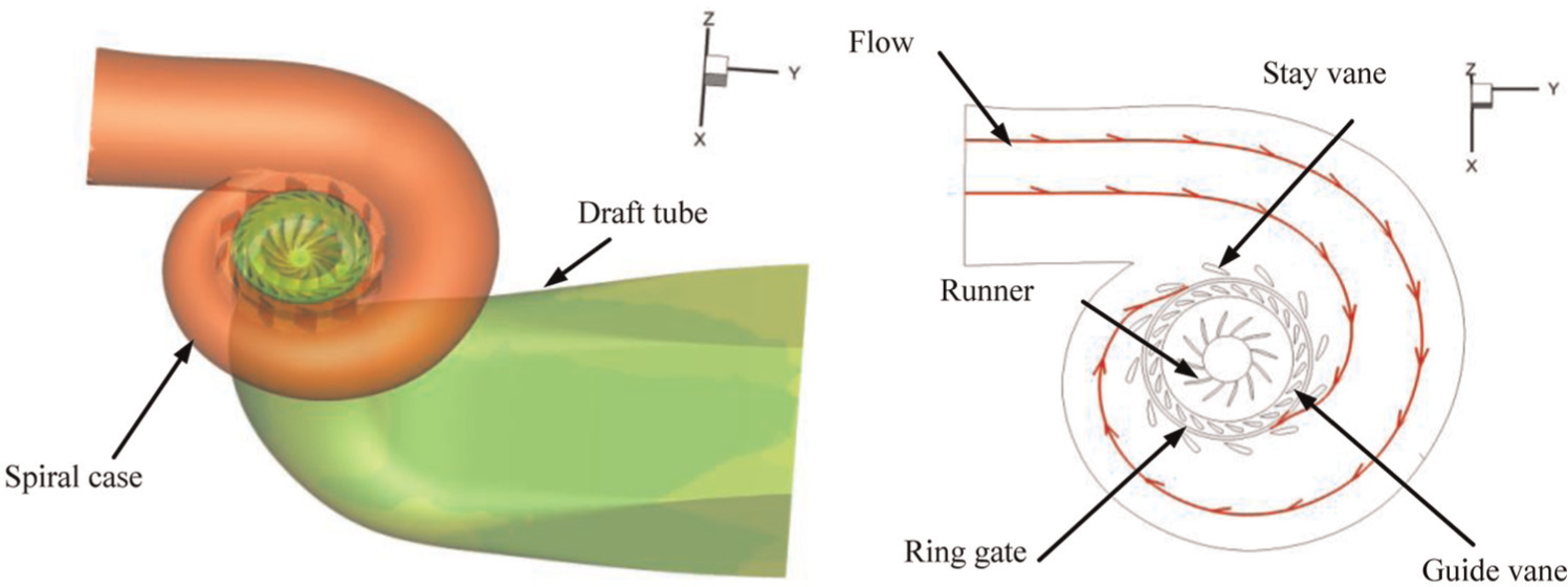
Schematic illustration of the model components used to model the entire flow through the turbine.

(a) Sketch of hydrodynamic forces acting on the ring gate and (b) photograph of experimental apparatus.
During an emergency shutdown, the hydrodynamic force acts on the ring gate mainly on the top surface, the bottom surface, and the inner and outer surfaces. The shape of the bottom surface of the ring gate is crucial because it determines the flow regime between the gate bottom and the gate seat. Thus, in this work, we use a bottom surface with a front angle α = 6°, which is widely used in such engineering applications.
The resultant axial hydrodynamic force Fd acting on the ring gate is called the hydrodynamic downpull force. If the direction of the hydrodynamic downpull force is positive, the downpull force will pull the ring gate down. If it is negative, it obstructs the closing of the ring gate. The hydrodynamic force acting on the top surface, the bottom surface, and the internal and external surfaces of the ring gate are Ft, Fb, Fi, and Fe, respectively. These are shown in Figure 2(a).
Control equations
During emergency closing, the 3D fluid flow around the ring gate is unstable, incompressible, and turbulent. By considering the effects of separation flow and vortex flow, the RNG k–ε turbulence model can accurately predict the flow near the wall area, 12 which is why we use this method in this work. The control equations for the flow are the following:12–16
Continuity equation

Momentum equation

RNG k–ε double equation


In these equations, xi and ui (i = 1, 2, 3) represent the Cartesian coordinate components and the velocity components, respectively; p, v, and fi represent the pressure, the kinematic viscosity coefficient, and the mass force, respectively; υt = cuk2/ε is the turbulent viscosity coefficient; cu = 0.09; σk = 1.0; σε = 1.33; C1ε = 1.44; and C2ε = 1.42. 13 The Reynolds stress-closure problem is solved by restructuring the group k–ε (RNG k–ε) two-equation model.
Numerical simulation
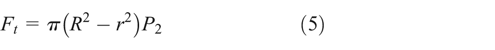
The target of the simulation is the flow around the ring gate. However, to fully consider the interaction between the ring gate and the adjacent flow components and to provide more accurate boundary conditions, we use the entire hydraulic passage of the model turbine as the computational fluid domain. 12 This domain is divided into six zones: inlet spiral case, ring gate, stay vanes, guide vanes, runner, and draft tube. Figure 1 shows a 3D geometric model of the entire flow passage through the model turbine. The inlet, outlet, and walls of the full flow passage in turbine runner are used as the boundary conditions. 13 Based on the actual working conditions of the ring gate, the inlet velocity is V = 5.13 m/s and the head is H = 50 m. The outlet is directly connected to outside rivers, and the pressure at the outlet is the standard atmospheric pressure.
In this work, to consider the specific circumstances of the present problem, the entire flow passage is divided into blocks of grids in six regions of the turbine. Excluding the relatively fine structured grid that is used near the areas where the gate moves, the rest of the computational regions consist of unstructured grids. Based on an analysis of grid independence, we use 1.89 million grid elements. The mesh scheme of the entire turbine flow passage is shown in Figure 3.

CFD mesh scheme of entire turbine flow passage.
For this work, we use Fluent, which is a commercial CFD code, to simulate the flow field in the turbine model. The finite-volume method is used to discretize the governing equations (continuity equation and momentum equation) within the computational region. The second-order upwind scheme is used as the convective term and the second-order central difference scheme provides the diffusion and pressure terms for the motion equations. We use the pressure-coupled SIMPLE algorithm (a semi-implicit algorithm) to solve the iterative flow-field equation. This algorithm is used to solve the Navier–Stokes equation for problems involving coupled velocity and pressure in incompressible fluids.
Calculation of hydrodynamic downpull force
We now explain how we calculate the hydrodynamic force Ft; two ring seals are fitted: one at the inside and one at the outside of the ring gate. The viscous flow and leaks in the ring gate seal are not taken into account. The pressure P2 acting on the top surface of the ring gate is the average of P1 and P3, which in turn represent the mean pressure upstream and downstream, respectively, of the ring gate seal. Therefore, Ft may be calculated as follows
In equations (5)–(7), R and r represent the radii of the outer and inner ring gate seal, respectively; P1i and P3i represent the pressures at the ring gate seal inlet P1 and outlet P3, respectively (see Figure 4); and n represents the node number of P1 or P3.

Pressure-monitoring points located at seal inlet and outlet of ring gate.
To investigate the pressure variations along the ring gate seal inlet and outlet during emergency shutdown, we defined four pressure-monitoring points PI1–PI4 and PE1–PE4 distributed evenly at the same radial position inside and outside the ring gate, respectively. All pressure-monitoring points are shown in Figure 4, where φ represents the angle of the spiral case.
The shape of the bottom surface of the ring gate determines the flow regime in this area and has a critical influence on the hydrodynamic force under the ring gate. To study the hydrodynamic vertical force acting on the bottom of the ring gate, we must first analyze the pressure distribution. As shown in Figure 2(a), the gate bottom is equally divided into three observation zones (A, B, and C) from inlet to outlet. Four points are spaced equally on its periphery. For example, point PA1 is at the periphery of the ring gate and its angle is φ = 0°.
To design the ring gate, the hydrodynamic vertical force is decomposed into four forces acting on the top, bottom, and internal and external surfaces of the ring gate. The algebraic sum of the vertical components of these forces is called hydrodynamic downpull force and is calculated as follows

Results and discussions
Verification of numerical computation validity
To test that the numerical solutions are independent of grid number, three different grid numbers are used in the numerical computation: 1.2, 1.89, and 3.2 million (see Table 1). By comparing the result calculated for the three different grid numbers for the force acting on the gate bottom when the ring gate is at 69.20% closing position, we find less than 2% difference between the grids with 1.89 and 3.2 million elements. Therefore, considering computation time and accuracy, we use herein the grid with 1.89 million elements.
Results and deviation of different grid numbers.

In order to verify the validity of the numerical computation results, the real machine test of hydrodynamic closing of ring gate was conducted at the Nansha Hydropower Plant. Since the downpull force and the operating force of the ring gate are of an approximately equal value but opposite directions, the hydrodynamic downpull force can be obtained by testing the operating force of the ring gate.10,11Figure 5 shows the comparison of downpull force with real machine test results. From Figure 5, it can be seen that the downpull force predicted by numerical method is in substantial agreement with the real machine test results. Thus, the computed results of the hydrodynamic downpull force are reliable. But there is a deviation between them because some influence factors are ignored, including the friction between piston and inner surface and the loss of inlet and outlet operation forces.

Downpull force compared of with real machine test results.
Analysis of flow field
To study how closing the ring gate affects unstable flow around it, we show in Figure 6, 2D velocity field with the ring gate 10%, 40%, 85%, and 99% closed. Figure 6 shows that when the ring gate starts to close, relatively stable flow lines exist inside the ring gate. With the ring gate approximately 40% closed, a recirculation zone arises inside the ring gate as the stream flow detaches downstream of the bottom of the ring gate. As the ring gate closes further, the recirculation zone becomes more pronounced, in accordance with the position of the ring gate. The variation of the recirculation zone affects the velocity field and the pressure distribution around the ring gate, in particular due to the formation of a local low-pressure area inside the ring gate, as shown in Figure 7(a).

Velocity and 2D streamline distributions for ring gate cross section at φ = 90° (labels “E” and “I” indicate the external and internal surfaces of the ring gate, respectively).
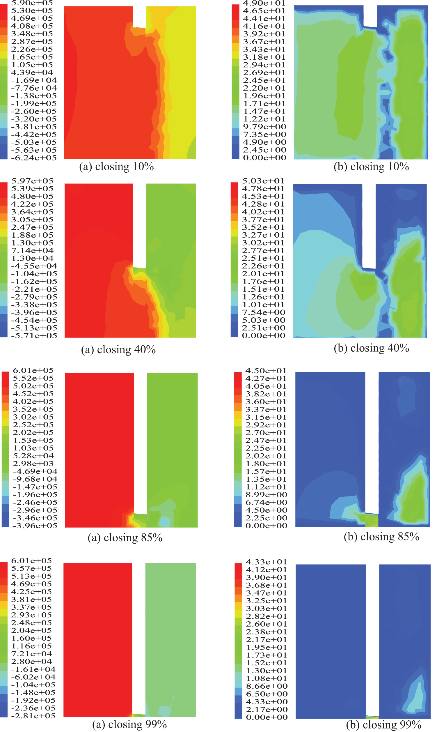
(a) Pressure (Pa) and (b) velocity (m/s) distributions at cross section φ = 90° of the ring gate for various stages of ring gate closure.
Figure 7 shows the distribution of pressure and velocity around the ring gate. Figure 7(b) shows that, upon closing the ring gate, the fluid velocity under the bottom of the ring gate gradually increases. For example, for the ring gate 10% and 40% closed, the velocity reaches 16.2 and 21.0 m/s, respectively. When the ring gate is approximately 85% closed, a high-velocity jet flow appears under the bottom of the ring gate and the velocity reaches 28.1 m/s. Thus, the position of the ring gate strongly influences the velocity field, which means that the position of the ring gate head modifies the velocity field around the ring gate.
Figure 7(a) shows that a low-pressure zone is induced by flow acceleration under the ring gate. Along the direction of flow of the fluid, the pressure around the ring gate gradually decreases, with negative pressures even occurring inside the ring gate. For example, when the ring gate is at 10% and 40% closing position, the pressure reaches −1.96 MPa at some positions inside the ring gate. These results occur mainly when the ring gate is partially closed and lead a quickly diminishing circulation area, an increasing fluid velocity, and a rapidly decreasing pressure. When the ring gate is nearly completely closed, this phenomenon becomes more apparent. Thus, flow acceleration under the ring gate is the main factor causing the low-pressure zone inside the ring gate and under the bottom of the ring gate. In addition, the resulting fluctuations in pressure cause not only the hydrodynamic force to fluctuate but also the flow-induced vibrations on the ring gate.
Analysis of vertical hydrodynamic force
Table 2 presents the hydrodynamic friction force that acts on the internal and external surfaces of the ring gate. The results in Table 2 show that the hydrodynamic friction force acting on both internal surface and external surface reaches a maximum when the ring gate is nearly completely closed. The force Fe on the external surface reaches 804 N, and the force Fi on the internal surface reaches 415 N. The direction of the hydrodynamic friction force is consistent with that of the flow because water is a viscous fluid; therefore, when the water flows through the external cylinder of the ring gate, it generates a frictional force in the flow direction and acts on the external cylindrical surface of the ring gate. Thus, due to its small impact on the ring gate, the frictional force is essentially negligible in the z direction.
Hydrodynamic friction force.
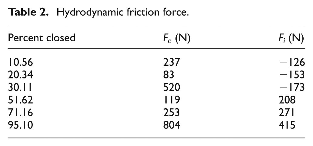
Figure 8(a) shows the pressure at the four monitoring points (PE1–PE4) as a function of gate-closure percent. The curves for the different points are nearly the same. At the moment the gate closes, the pressure at each point reaches a peak value. For example, the pressure at PE1 starts at 0.54 MPa and then gradually decreases. At 5% closed, the pressure of the four points reaches a minimum (e.g. the pressure of PE1 is 0.49 MPa at 5% closed). From 5% to 40% closed, the pressure at PE1 is the largest, followed in order by PE2, PE3, and PE4. This is because, when the ring gate starts to close, the inflow condition in the circumferential direction is not identical. From 40% to 100% closed, the pressure increases monotonically, and the difference between the four points becomes smaller.

Pressure at points (a) PE1–PE4 and (b) PI1–PI4 as a function of gate closing.
However, the pressure at the four monitoring points PI1–PI4, which are at the ring gate seal outlet, gradually decreases over the entire closing process (see Figure 8(b)). The main reason for this is, as mentioned in the analysis above of the flow field inside the ring gate, the low-pressure areas extend to the ring gate seal outlet because of the high-velocity jet flow under the bottom of the ring gate. Based on the analysis above, the pressures in the circumferential direction at PE1–PE4 along the seal inlet and at PI1–PI4 along the seal outlet differ only by a very small amount. Thus, the pressure P2 at the top surface can be taken as the mean of the pressures P1 and P3. The pressure P2 can be approximated as follows

Figure 9 shows the pressure distribution at the bottom surface of the ring gate during the closing process. The pressures at the 12 monitoring points vary in the same way as the pressure on the internal and external surfaces. When the ring gate begins to close, the pressures at the 12 monitoring points increase very rapidly to a peak value of 0.55 MPa. The main reason for this is that the gate body enters the main area of high-velocity stream and causes the “water hammer” phenomenon. As the ring gate continues to close, the upstream flow begins to gradually separate from the bottom of the ring gate. When the ring gate is 65% closed, the pressure at the monitoring points reaches a minimum; this occurs mainly because flow separation is more obvious at the bottom surface of the ring gate, which disturbs the flow and thereby consumes a lot of energy, so that the positive pressure of the bottom surface drops to a minimum. However, as the ring gate continues to close, the pressure begins to increase again. When the ring gate is almost completely closed, the pressure approaches the upstream-head hydrostatic pressure.

Pressure variation curves at points (a) A1–A4, (b) B1–B4, and (c) C1–C4 during the gate-closing process.
From Figure 9, we also see that the pressure variation at the 12 monitoring points in the circumferential direction of the ring gate is not uniform, which may lead to an overturning of the ring gate. The main reason behind this is the different inlet conditions in the circumferential direction. For example, the inlet conditions differ for the stay vane and the guide vane and for the inside and outside of the ring gate. In addition, the upward transmission of the draft tube vortex vibration causes unstable flow in the ring gate area.
However, during the entire closing process, almost no negative pressure acts on the bottom surface of the ring gate, which is mainly because the bottom lip is reasonable and basically forms a streamline profile, so that the pressure distribution at the bottom surface of the ring gate upholds due to the well-flow regime. In general, the upholding force is harmful to the closing of the ring gate, whereas beneficial to the opening of the ring gate.
Figure 10 shows the hydrodynamic vertical forces on the ring gate as a function of gate-closing percent. For ring gate closure from 0% to ∼90%, the hydrodynamic vertical force Fb that acts on the bottom surface of the ring gate decreases gradually, which is attributed mainly to the variation in the direction of fluid flow. However, after the ring gate is 90% closed, the hydrodynamic vertical force Fb rises sharply. By comparing the variation in the vertical hydrodynamic forces before and after 90% closure, we see that the variation of the former is gentle and that of the latter is relatively sharp. Before 90% closure, a small variation in the position of the ring gate causes only a slight variation in the hydrodynamic force on the bottom of the ring gate. However, as the ring gate approaches almost-complete closure, a slight variation in ring gate position or a slight lateral displacement of the ring gate between the guides modifies the field of flow passing the ring gate, resulting in a large variation in pressure on the bottom surface of the ring gate. In other words, the hydrodynamic force on the bottom surface of the ring gate is more sensitive to the position of the ring gate when the latter is nearly closed. These unbalanced pressures around the periphery of the ring gate cause it to move in the direction of lowest pressure.
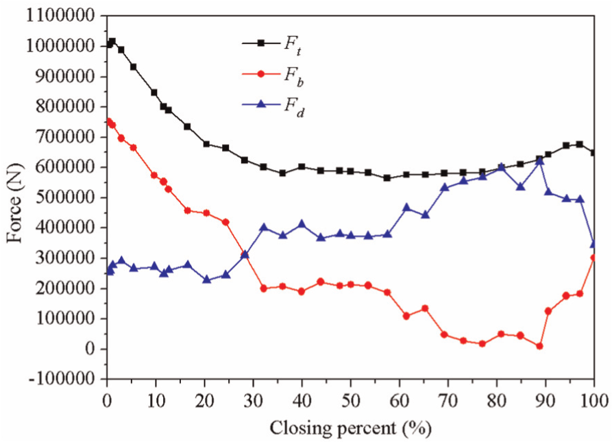
Vertical hydrodynamic force as a function of gate-closing percent.
Figure 10 also shows that from 0% to 90% closure, the hydrodynamic downpull force Fd increases. Near 90% closure of the ring gate, this force reaches a maximum value of 600 kN. This occurs mainly because the pressure on the bottom of the ring gate drops its minimum value at 90% closure. From 90% to 100% closure, the hydrodynamic downpull force drops dramatically. However, during the entire closing process, the direction of hydrodynamic downpull force Fd is downward. Thus, at all times during the closing of the ring gate, the hydrodynamic downpull force always acts to close the ring gate. These computational results for the hydrodynamic downpull force are consistent with the measurements of axial operation force in Li et al. 8
Conclusion
We numerically simulated the 3D turbulent flow in a Francis turbine. The simulation is based on the incompressible continuity equation and the Reynolds-averaged Navier–Stokes equations, together with RNG k–ε double-equation turbulence model. The flow field around the ring gate is analyzed during emergency shutdown. Based on these analyses, we calculate the hydrodynamic forces acting on the ring gate. The following main conclusions are drawn from this study:
The pressure and velocity distribution under the gate bottom are affected by the position of the ring gate as it closes. This effect is more obvious at small openings (i.e. ring gate is almost closed) than at large openings. A high-velocity jet flow forms under the bottom of the ring gate. This flow is unstable and leads to fluctuations in the hydrodynamic force on the ring gate.
During the entire closing process, the pressure distribution on the bottom surface of the ring gate is upholding. The pressure varies similarly at all observation points. The minimum value of the resultant vertical force occurs when the ring gate is at 90% closing position.
The hydrodynamic force on the top surface of the ring gate remains almost constant, so the hydrodynamic downpull force reaches a maximum value when the ring gate is at 90% closing position. Throughout the entire closing process, the hydrodynamic force always acts to close the ring gate. This is favorable for closing the ring gate and is not favorable for opening the ring gate.
Footnotes
Academic Editor: Jiin Y Jang
Declaration of conflicting interests
The authors declare no conflicts of interest regarding the publication of this article.
Funding
This work was sponsored by the Key Technologies R&D Program of Tianjin under Grant No. 09ZCKFGX03400 and by the Youth Scholar Foundation (B type) of Tianjin University under Grant No. TJU-YFF-08B24.