
Abstract
This article presents a magnetic actuator for use in a separable electric connector based on conical airgap. The magnetic flux lines in conical airgap are almost vertical to the edge face of the yoke and armature, showing that the actual flux length in conical airgap is smaller than the axial stroke, which reduces magnetic reluctance over large stroke. Parameter improvement is analyzed based on modeling, and optimal results of the magnetic actuator are adopted to improve the rate of force to volume. The experimental results show that there is friction force of 10–12 N existing in the moving armature of the prototype, and the nominal value is in accordance with the simulation one. The results show that the design of conical airgap in the magnetic actuator is available to improve the initial force and reliability of the separating process and has the advantages of compact structure, short transmission, high reliability, large force with 50 N at the initial displacement of 2.5 mm, and fast response with 16.5 ms over the traditional actuator.
Introduction
A separable electric connector is applied to the connection between the military electronic system and the equipment on the ground as well as a variety of electrical, electronic equipment and a series of industrial equipment, such as LEMO Group connector. The separable electric connector may operate in transient separation by magnetic or mechanical force. Magnetic separation is requested to improve the automatic control level of the separable electric connector in aerospace field such as rocket launcher, so an actuator needs to be adopted to produce large magnetic force for separation of the connector. As a traditional actuator, rotating motor relies on a set of gear mechanisms to transform rotation motion into straight line motion. Due to transmission error by existence of gap in gear mechanism and low efficiency by multiple transformation process, it is difficult for the traditional actuator to meet the developmental requests for short transmission of the component in aerospace field. At present, direct-drive magnetic actuators1–3 are widely applied in straight line motion and have advantages of compact structure, low cost, and high efficiency over the traditional one.
With the expanding of complex application, the requests for high-performance magnetic actuator are increasing. Optimal configuration for direct-drive magnetic actuators has attracted widespread attention in recent years.4,5 Usual actuators with cylindrical airgap show that the force decreases obviously as the displacement of airgap increases.6–8 Other actuators for hydraulic valves based on corner-pole airgap in previous work have shown good linear characteristic in the application of high fluid pressure, but the structure of welding sleeve increases the complexity and cost of the actuators.9,10 In order to expand the application of magnetic separation in the separable electric connector, it is available to improve the rate of force to volume, which is the research trend and design difficulty of direct-drive magnetic actuators with high speed and high reliability in limited space.11–14
The article presents a magnetic actuator for a separable electric connector based on conical airgap. The mathematical model of the magnetic actuator is established, and the magnetic flux distribution in conical airgap is given. Parameter improvement for the structure of the magnetic actuator is analyzed based on modeling. The simulation results and the experimental results of static force characteristic are compared.
Structure and method
Introduction to separable electric connector
A separable electric connector includes a plug and a socket and can be mated by simply pushing the plug axially into the fixed socket. The plug of a separable electric connector is described in Figure 1 and consists of contacts, tube, filler, locking ball, plunger, pushers, springs, a magnetic actuator, and so on. When mated straightly, the contacts are inserted into fixed sockets, and the pushers are drawn back against the compressed springs. Meanwhile, the plunger is pushed out of the tube and presses the locking ball firmly by cylinder of large diameter to latch the connected plug and socket. If separation is required, the plunger should be pulled back by the magnetic actuator to disengage the locking ball. Without the latching force on the locking ball, the plug could be withdrawn from the socket by the compressed springs to achieve the separating process. The separating process of the connector takes place only in transient status, and electric technology of high pulse voltage 15 has been adopted in the control method of the magnetic actuator to improve the speed and reliability of the separating process.

Plug structure of a separable electrical connector: (1) magnetic actuator, (2) springs, (3) plunger, (4) filler, (5) tube, (6) locking ball, (7) contacts, and (8) pushers.
Structural design based on conical airgap
The magnetic actuator investigated consists of shell, coil, coil terminal, sleeve, yoke, spring, armature, plunger, and so on, as shown in Figure 2. The coil winding is assembled among the sleeve, yoke, and shell. The coil terminal passing through the edge face of the shell is connected to an electric control unit. The armature is formed into cylindrical shape with one terminal of inner conical hole and glides in the non-magnetic sleeve. The plunger passes through the axial center of the yoke and the armature and clings tightly to the armature by a compressed spring, which is assembled among the yoke and the plunger. Taking advantage of the above structure, conical airgap is designed in the operating area between the yoke and the armature, resulting in lower magnetic reluctance under large stroke than cylindrical airgap existing in the usual actuator. The shell, yoke, and armature of the prototype are made of the widely applied magnetic material of pure iron.

Structure of the magnetic actuator: (1) yoke, (2) spring, (3) coil, (4) sleeve, (5) shell, (6) armature, (7) coil terminal, and (8) plunger.
Actuator modeling
Mathematical modeling
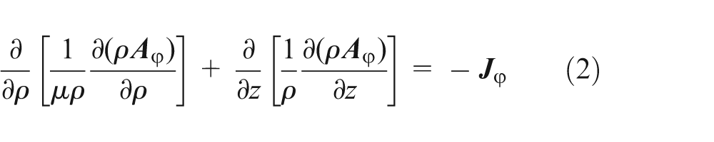
Neglecting the displacement current and the hysteresis, static electromagnetic field governing equation in terms of the magnetic vector potential, derived from the Maxwell equations, is

where
As the structure of the proposed magnetic actuator is symmetric to the central axis, the cylindrical coordinate (ρ, φ, z) is adopted for the axisymmetric magnetic field. If
Then, a three-dimensional problem can be simplified as a two-dimensional one in case of axisymmetric magnetic field, and the magnetic field governing equation is simplified as
As the magnetic actuator is probably operated in a partially saturated condition, the nonlinear characterization of the magnetic material of the widely applied pure iron should be included in numerical simulation; the permeability µ is a function of the magnetic field intensity

The boundary condition is a key factor to solve the electromagnetic problem and includes first boundary condition and second boundary condition.
The first boundary condition is expressed as

The second boundary condition is expressed as

To predict the static force characteristic of the magnetic actuator, the mathematical model is established combining (2)–(5), taking into account the nonlinear characterization of the magnetic material, and is the theorical basis for solving the finite element model16,17 in the next step.
Finite element model
The specific actuator model is established in two-dimensional electromagnetic finite element software of Maxwell to investigate static force characteristic. Boundary and exciting conditions of the model for the magnetic actuator are shown in Figure 3. Exciting current under certain voltage is specified into the coil windings. Except the default (first) boundary condition, the symmetric condition is assigned in the center axis, and the balloon (second) boundary condition is assigned for the background object as extending to infinity along the edges. The grid mesh of the model for the magnetic actuator is shown in Figure 4. Fine mesh in and near conical airgap is given to improve the calculation accuracy. The initial direct current magnetization curve of the widely applied pure iron material is shown in Figure 5.

Boundary and exciting conditions of the model.
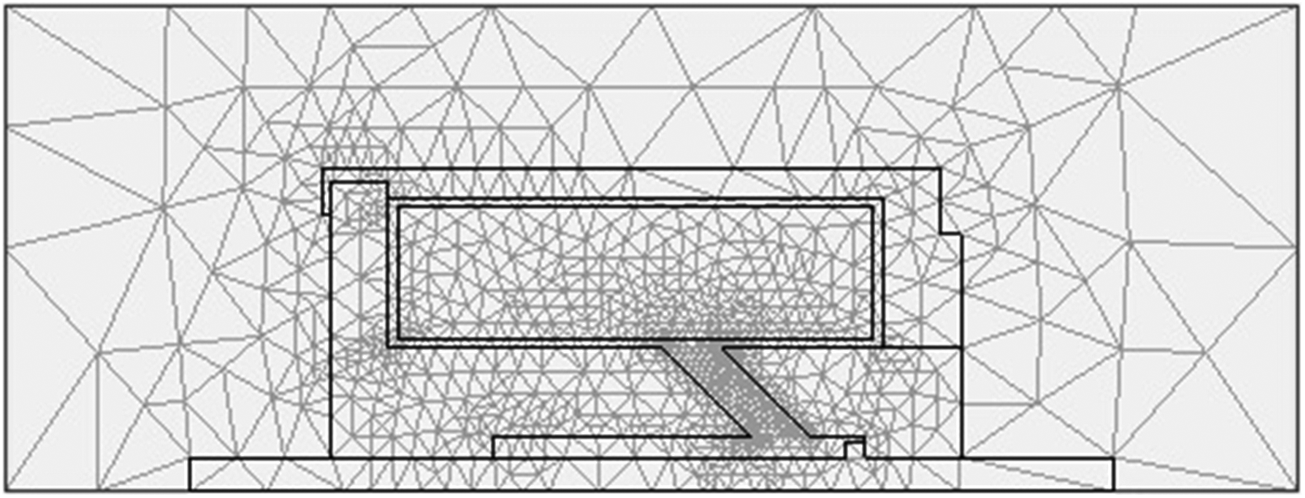
Grid mesh of the model.

Magnetization curve of the widely applied pure iron material.
Magnetic flux distribution in conical airgap
Based on modeling, the magnetic flux distribution in the magnetic actuator is given in Figure 6. When the coil is energized, the magnetic fluxes have closed loop passing through the shell, yoke, conical airgap, armature, and back to the shell. Especially in conical airgap, magnetic flux lines are almost vertical to the edge face of the yoke and the armature so that the actual flux length in conical airgap is shorter than the axial stroke, which reduces magnetic reluctance over large stroke, and the design of conical airgap is available to improve the initial force over large stroke in limited space.

Magnetic flux distribution in the magnetic actuator.
Parameter improvements based on modeling
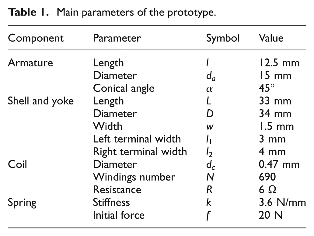
From the magnetic flux distribution, the parameters along the flux path described in Figure 7 (detailed explanation in Table 1) have major effects on force characteristic in limited space, such as conical angle α, armature length l, shell width w, and coil diameter dc. So, the improvement in each key parameter for the magnetic actuator is discussed, respectively, below.
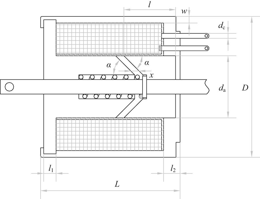
The parameters of the magnetic actuator.
Main parameters of the prototype.
Conical angle α
To investigate the effect of conical airgap on force characteristic, the conical angle is set to be a variable value in the model. Figure 8 gives the displacement–force curves under three conical angles of 30°, 45°, and 60° based on modeling. As the angle value increases, the displacement–force curve tends to be a large slope one, and force is reduced immediately in large displacement. So, the design of large conical angle such as rectangular angle used in traditional cylindrical airgap is not suitable for operating over large displacement, due to large magnetic reluctance in operating airgap resulting in small initial force. Oppositely, when the conical angle α is set to be 30°, the differential value between the initial force and the terminal force is reduced due to saturated magnetic flux by small magnetic reluctance, so the curve tends to be flatter than other two values. Design of small conical angle is available to improve initial force over large displacement in limited space as described in the above section, but reduces terminal force over small displacement, which may lead to an inadequate separating process. So, a medium conical angle is adopted to balance the conflict of initial force and terminal force and is available to improve the initial force and reliability of the separating process.
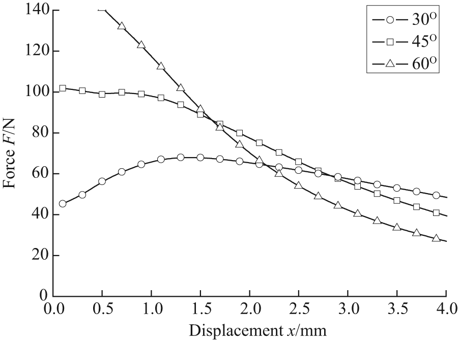
Displacement–force curves under three conical angles.
Armature length l
Figure 9 gives the displacement–force curves under three armature lengths of 10, 12.5, and 15 mm based on modeling. As the armature length increases and initial force remains unchanged, but terminal force increases immediately. So, the design of large armature length can ensure the reliability of the separating process. However, too large length increases the volume, mass, and terminal impact force of the moving armature and makes no sense to the speed and smoothness of the whole separating process, as well as the rate of force to volume. So, a medium armature length is adopted to obtain a suitable displacement–force curve, withstanding the load force.
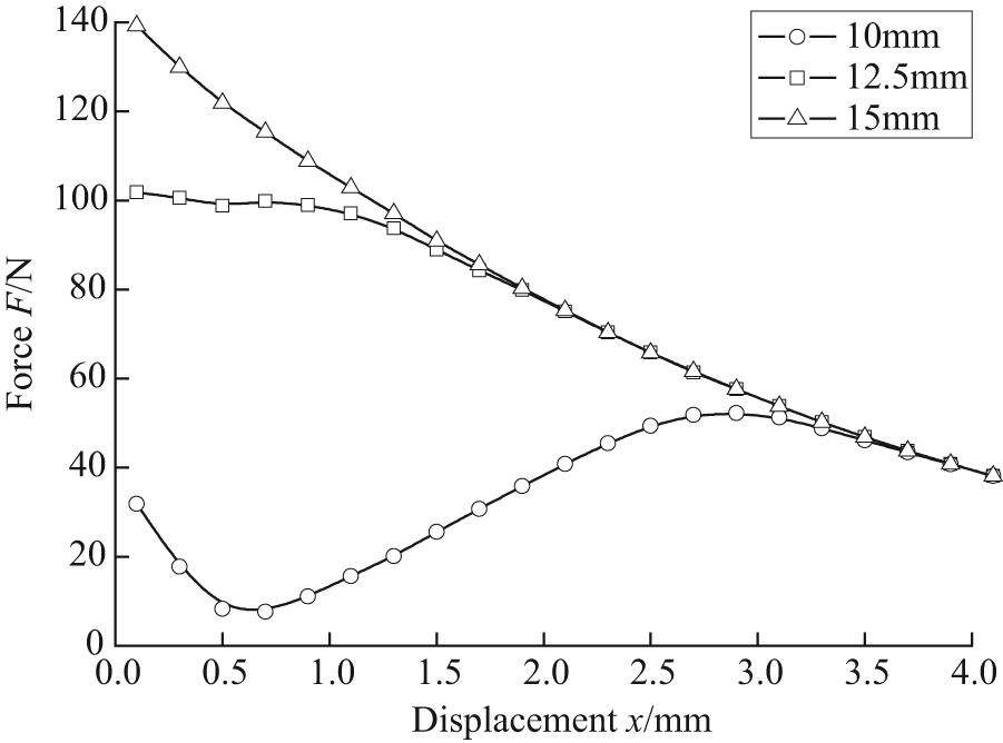
Displacement–force curves under three armature lengths.
Shell width w
Figure 10 gives the displacement–force curves under three shell widths of 1, 1.5, and 2 mm based on modeling. As the shell width increases, the force increases in the whole stroke range and tends to a saturated value after a certain value. For example, the increase rate from width of 1.5 to 2 mm is only one-fourth of that from width of 1 to 1.5 mm. Due to large shell width representing large volume and mass of the magnetic actuator, the design of shell width according to the point of producing saturated force can obtain an optimal rate of force to volume.

Displacement–force curves under three shell widths.
Coil diameter dc
Figure 11 gives the displacement–force curves under three coil diameters of 0.45, 0.47, and 0.49 mm based on modeling. In the condition of 18 V constant voltage source, as the coil diameter increases, the force increases proportionally. This is due to increased input power upon low resistance with increased coil diameter. To improve the rate of force to volume, maximum input power is needed, but it cannot exceed the rate driving capability with a current of 3 A. So, the value of coil diameter is adopted to fulfill the rate driving capability.

Displacement–force curves under three coil diameters.
Besides, other structural parameters such as armature diameter da, left terminal width l1, and right terminal width l2 are optimized to improve the rate of force to volume over the stroke range based on modeling, which are omitted here. A prototype in Figure 12 could be developed through the above process, and the detailed dimensions are shown in Table 1.

Prototype of the magnetic actuator: (1) coil terminal, (2) shell, (3) sleeve, (4) yoke, (5) armature, (6) spring, and (7) plunger.
Experimental validation
A test system 18 for the static force characteristic of the prototype is shown in Figure 13. The plunger of the prototype without spring is connected to force sensor, displacement adjustment mechanism, and a displacement sensor on one platform in order to keep in coaxial arrangement. The coil terminal of the prototype is directly connected to a constant voltage source. When the prototype is energized, the displacement and force of the plunger are recorded on a LabVIEW system. Thus, as the displacement of the plunger can be adjusted by the displacement adjustment mechanism of double nut and screw, the force hysteresis characteristic of the prototype under bidirectional movement can be obtained.
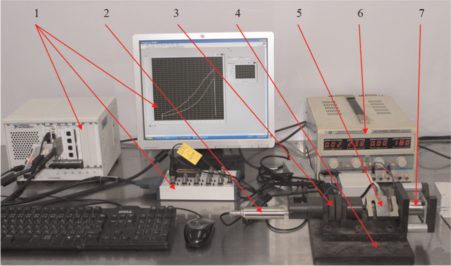
Test system for static force characteristic of the prototype: (1) LabVIEW system, (2) displacement sensor, (3) displacement adjustment mechanism, (4) platform, (5) force sensor, (6) constant voltage source, and (7) the prototype.
Figure 14 gives the static force characteristic of the prototype under a constant voltage of 18 V. The experimental results have hysteresis curves, and the direction of the arrow tip represents the test direction of the moving armature. When the armature moves from the initial position to the terminal position by the displacement adjustment mechanism, the curve line with positive direction is measured to be lower than the simulation one. Oppositely, the line with negative direction is measured to be larger than the simulation one. The hysteresis value is calculated to be 20–24 N, which is due to inevitable friction force existing in the moving armature, so we can deduce that the friction force ignored in the simulation model is half of the hysteresis value (i.e. 10–12 N).19,20 The nominal value of the experimental curves is in accordance with the simulation one, except in the displacement of small airgap. In the separating process of the connector, magnetic force always overcomes the friction force, so the actual output force is the curve under the simulation one, which is about 50 N at the initial displacement of 2.5 mm.

Comparison of experimental and simulation results.
When the spring is assembled in the prototype, the experimental results on the dynamic displacement characteristic can also be obtained by a high-frequency laser displacement sensor (sample frequency of 2.5 kHz, proportional gain of 5 mm/V). Under pulse voltage of 18 V, the variable displacement in the separating process could be measured. Figure 15 gives the pulse response process of the prototype with spring (spring constant of 3.6 N/mm, compressed force of 20 N at the initial displacement of 2.5 mm). The results of both the current and displacement curves show that the whole separating time with stroke of 2.5 mm is measured to be 16.5 ms, among which only 4.5 ms is used as the motion of the armature. So, the proposed prototype with improved force characteristic can operate reliably on separating motion with a fast response time of 16.5 ms within stroke of 2.5 mm. So, the pulse voltage with width of 20 ms is enough to operate in transient separation for the prototype.

Pulse response process of the prototype.
Conclusion
A magnetic actuator for a separable electric connector based on conical airgap is presented. Both magnetic flux distribution in conical airgap and parameter improvement show that the design of conical airgap is available to improve initial force over large stroke in limited space. The established model could be used for parameter improvement of the magnetic actuator, and simulation results show that optimal results for the magnetic actuator such as conical angle, armature length, shell width, and coil diameter are adopted to improve the rate of force to volume. The experimental results show that there is friction force of 10–12 N existing in the moving armature of the prototype, and the nominal value is in accordance with the simulation one, except in the displacement of small airgap. In the separating process of the connector, magnetic force always overcomes the friction force, so the actual output force is the curve under the simulation one, which is about 50 N at the initial displacement of 2.5 mm. Assembled with a given spring, the whole separating time of the prototype within stroke of 2.5 mm is measured to be 16.5 ms, among which only 4.5 ms is used as the motion of the armature. The magnetic actuator based on conical airgap is suitable for application in the separable electric connector of aerospace field.
Footnotes
Academic Editor: Makoto Hasegawa
Declaration of conflicting interests
The authors declare that there is no conflict of interest.
Funding
This work was financially supported by National Natural Science Foundation of China (51305305), Zhejiang Provincial Natural Science Foundation of China (LQ13E050010), Open Foundation of the State Key Laboratory of Fluid Power Transmission and Control (GZKF-201307), and Zhejiang International Science and Technology Cooperation Project (2013C14015).