
Abstract
To analyze the fluid–solid coupling stress characteristics of the Francis turbine runner comprehensively, based on the Reynolds-averaged Navier–Stokes equations and shear stress transport k-ω turbulence model, this article performs numerical simulation of three-dimensional steady incompressible turbulent flow through the whole passage of a certain large Francis turbine under multiple operating conditions with Computational Fluid Dynamic software CFX and contrasts the result with that model test conversion. With the help of ANSYS workbench platform, equivalent stress, deformation distribution, and variation of the runner under multiple operating conditions are obtained through loading the water pressure on the runner blade as structural plane load to blades by the method of unidirectional fluid–solid coupling. The results show that under small flow operating conditions, flow patterns in the runner are disordered, the stress on the blade distributes unevenly, and the maximum stress lies on the influent side of the blades connected to the band; as the flow increases, the stress appears intensively around the effluent side of the blades connected to the runner crown. The maximum deformation first decreases and then increases as the flow increases. The deformation area expands from the middle effluent side of blades to the band. The results can be found in the researches on the structure design and the safety and stability of the Francis turbine runner.
Introduction
In recent years, vibration and cracks on the runner blade have frequently occurred to a series of large Francis turbine units, which threatens the safety and steady operation of the units. With the development of fluid–solid coupling technology, many scholars are carrying out research on the fluid–solid coupling stress characteristics of fluid machinery. Jiang et al. 1 predicted the structural vibration and noise of water conservancy under the induction factors. Gorla et al. 2 evaluated the stresses and their variations of critical points on the turbine blade. Xiao et al.3–5 performed computational fluid dynamics (CFD) calculation on the flow field of Francis turbine through the whole passage under multiple operating conditions, obtained the relation between the maximum static stress of the Francis turbine runner and the power of the turbine by means of ordered coupling calculation and analyzed the difference between the results of unidirectional fluid–solid coupling and bidirectional fluid–solid coupling calculations. Zhang et al. 6 calculated the static and dynamic stress of the tubular turbine runner with unidirectional and bidirectional fluid–solid coupling, respectively, and analyzed the reasons for cracks. Based on the ordered fluid–solid coupling, there is less research on the variation of the stress and deformation of Francis turbine runner under multiple operating conditions at home and abroad.
To analyze the fluid–solid coupling stress characteristics of the Francis turbine runner comprehensively, this article performs CFD calculations7–9 on eight guide vane openings of three different water heads through the whole passage of a certain large Francis turbine in the northeast of China. Based on the unidirectional fluid–solid coupling calculation, the maximum stress and deformation under different operating conditions of the runner are obtained, and this article analyzes the distribution and variation of the maximum equivalent stress and deformation with different water heads as the flow increases, thus realizing the check and prediction of the turbine runner intensity and providing reference for theoretical design and engineering application.
Flow field calculations
Calculation model and operating points
This article considers a certain large Francis turbine in northeastern China as research object and builds the calculation model of the whole passage from the spiral case inlet to the draft tube outlet, as presented in Figure 1. The feature parameters of the turbine are shown in Table 1. In order to analyze the flow and stress characteristics of Francis turbine comprehensively, this article chooses three different water heads, among which the smallest head is 81 m, the design head is 112 m, and the biggest head is 126 m. Under each head, there are eight conditions of different guide vane openings to be calculated. The eight conditions (from low to high) are 106.4, 156.5, 205.7, 254, 301.4, 347.7, 440, and 460 mm. The flow and entity section are modeled by Unigraphics (UG) modeling.

Geometric model of the Francis turbine.
Feature parameter of the Francis turbine.

Calculation method and mesh generation
The relative deformation of the Francis turbine runner influenced by the flow fields in the turbine is quite small. And the deformation of flow field in the turbine influenced by the runner is also quite small. Therefore, this article employs unidirectional fluid–solid coupling calculation without considering the effects of structural field changes on the flow field. This article performs steady calculation on the flow field in the turbine and considers the water pressure of the fluid–solid interface in the flow field calculation result as the load in the runner equivalent stress calculation.
The flow movement in the fluid machinery can be described by the simultaneous continuity equation and Reynolds-averaged Navier–Stokes (N-S) equation10–12
The continuity equation is

The N-S equation is

In the equations,
Generally speaking, water is an incompressible fluid and the heat exchange of it is very small, which lead to ignoring the energy conservation equation. When the closure problem in turbulent motion is described by the Reynolds-averaged N-S equation, the turbulent model is needed to close the equation set. This article uses the shear stress transport (SST) k-ω 13 model which can accurately simulate the near wall area to simulate flow characteristics of the computational domain.
The fluid domain includes the spiral case, the stay ring, the runner, and the draft tube. In the structural domain, only the runner is taken into account. In numerical calculation, grid is not only the indirect manifestation of geometric model but also an important carrier of numerical calculation and analysis. The quality of grid directly relates to the accuracy and efficiency of calculation and affects the validity and reliability of calculated results. There are a lot of flow passage components of the turbine through the whole passage, and the geometric shapes of them are complex. Considering the complexity of flow passage components’ geometric shapes, this article uses the Integrated Computer Engineering and Manufacturing code for Computational Fluid Dynamics (ICEM-CFD) for tetrahedral unstructured mesh generation which is more geometrically adaptable in the fluid domain and for mesh generation and local refinement on the spiral case, stay ring, runner, and draft tube, respectively. The grid of each part is shown in Figure 2. The number of grid units in the fluid calculation domain of the turbine is 3,252,528. The number of grid units in the spiral case, stay ring, runner, and draft tube is 308,714, 987,627, 1,696,713, and 259,474, respectively.
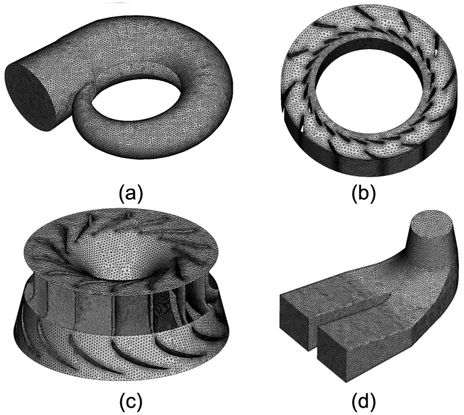
Grid of each part in the calculation domain: (a) spiral case, (b) stay ring, (c) runner and (d) draft tube.
Equation discrete conditions and boundary conditions
Numerical simulation was completed with software CFX. This article uses finite volume method to scatter the governing equation set. The diffusion term and pressure gradient are presented by finite element function, and the solving format of the convection term is of high order. The solution to the flow field is fully implicit coupling method, which is the coupling method of momentum equation and continuity equation. The boundary conditions are as follows: setting the given total pressure at the entrance, setting the free flow at the exit, and adopting heat insulation and no-slip conditions on the solid wall. The junction of the fluid domain of the runner and the runner entity is defined as the fluid–solid coupling boundary. The parameter transfer of the static and dynamic couplings between the runner and the stay ring and draft tube was dealt with the frozen rotor method. 14
Calculation results and analysis
The water pressure distributions on the blade under 24 conditions are calculated as the fluidsolid coupling surface load boundary conditions, in finite element analysis, of the runner stress characteristics. The design operating condition is chosen with the static pressure distribution on the blade, as shown in Figure 3.

Pressure distribution on the pressure surface and suction surface: (a) pressure surface and (b) suction surface.
Figure 4 shows the curves of efficiency versus flux concluded by the result of numerical simulation and model test conversion when Hmin, Hd, and Hmax are 81, 112, and 126 m, respectively. The flow patterns are fine under the condition of rated flow. The results of numerical simulation and model test are highly anastomosed. When the efficiency error is 1% deviation from the rated flow, the flow patterns are relatively complex and the accuracy of numerical simulation also decreases. Therefore, the difference is big. But the trend of three curves is generally in accordance and the maximum efficiency error is within 3%, which indicates that the numerical results can accurately reflect the flow characteristics of the calculation model. The information of pressure load on the runner surface can be accurately concluded by flow field solving, thus guaranteeing the stress characteristic analysis of the runner.
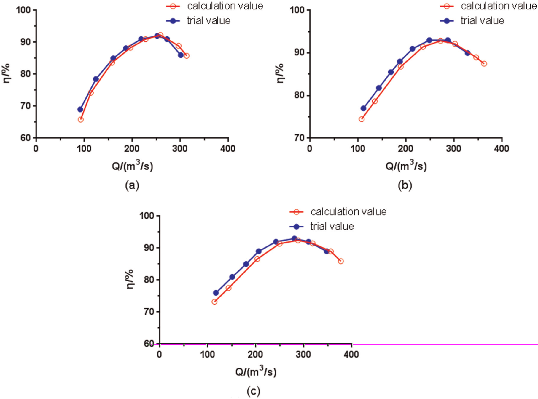
Curves of efficiency versus flux under three kinds of head: (a) H = 81 m, (b) H = 112 m, and (c) H = 126 m.
Structure field calculations
Calculation method of runner intensity
The finite element equation for runner intensity calculation15,16 is


In the equations,
According to the fourth strength theory and

In the equation,
Structure model and boundary conditions
The object of structure calculation is the runner of the Francis turbine. The material of the runner is ZG20SiMn, the properties of which are shown in Table 2. The grid unit of the runner size is set as 80 mm. The method of the runner's mesh generation is free. Since the stress intensively occurs in the blade root, 18 the grid in this area is encrypted. The mesh generation produces 1,743,812 units and 2,550,548 nodes, which are shown in Figure 5.
Properties of runner material.


Grid of runner.
The boundary conditions of the runner model include structural loads and constraints. 19 The two structural loads are as follows: inertia load, including acceleration of gravity and runner speed, and surface load, the water pressure on the fluid–solid coupling surface from flow field calculation above. In case the rigid body displaces, the runner boundary condition is set at the combined bolt to constrain the freedom of corresponding nodes. The load and constraint of the runner are presented in Figure 6.
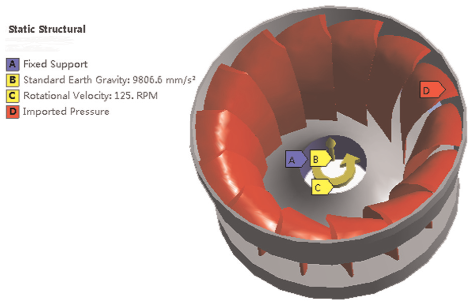
Runner boundary conditions.
Calculation results and analysis
The equivalent stress and deformation distribution of the runner under different operating conditions are concluded through solving the finite elements model. Considering the length of this article, only the equivalent stress distribution and deformation under three conditions, where the minimum flow a0 is 106.4 mm, design flow a0 is 347.7 mm, and maximum flow a0 is 460 mm, are contrasted and analyzed.
Stress distribution of the runner under different operating conditions
Figure 7 represents the runner equivalent stress distribution calculated according to distortion energy theory. From the figure, it can be seen that under the small flow operating condition, the stress on the blade surface distributes unevenly, and the stress on the influent side of the blade near the band, on the effluent side connected to the band, and on the effluent side of blades connected to the runner crown distributes intensively. Because the flow is small and the water flow patterns in the runner are disordered, the ability of water to function on the blade is weak and the pressure on the blade changes less and distributes irregularly. In the meantime, it is related to many other factors like the constraints on the blade from the runner and the combined bolt, the thinness of the effluent side of the blade, and so on. The maximum equivalent stress appears on the influent side of the blade connected to the band, because when the guide vane opening is small, the flowing state of water makes the high-pressure region of static pressure on the blade appear on the influent side of blade pressure surface near the band. At this moment, the static pressure on the other parts of the blade pressure surface is low or negative, which deeply affects the blade, thus making the stress concentration and maximum stress appear on the influent side of the blade connected to the band.
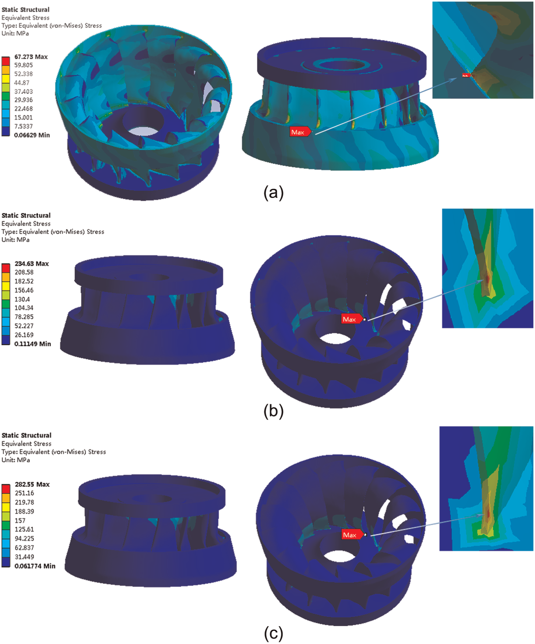
Equivalent stress charts and partly magnified stress charts for runner at various operating conditions: (a) the equivalent stress distribution under small flow, (b) the equivalent stress distribution under design flow, and (c) the equivalent stress distribution under large flow.
As the flow increases, the water flow patterns are gradually smooth, the pressure difference of the blade pressure surface and suction surface is large, the static pressure gradient on the surface is obvious, and the stress distribution goes even. The stress concentration and maximum stress appear on the effluent side of the blade near the runner crown. Because the boundary condition is set on the combined bolt of the runner and the spindle, when the pressure load is loaded to the blade, the bending moment and shear force near the fixed constraint are big and they cannot release the stress by bending or deforming. Meanwhile, the effluent side of the blade is thin and the stiffness and strength are insufficient, thus leading to the stress concentration and maximum stress here.
The runner deformation under different operating conditions
The deformation distribution of the runner is shown in Figure 8. In the figure, it can be seen that the maximum deformation appears in the middle of the effluent side of the blade. Because the static pressure on the blade surface is relatively small and uneven, the stiffness of the effluent side of the blade is insufficient and easy to deform, compared with the blade connected to the runner crown and the band. As the flow increases, the static pressure on the blade increases. The pressure gradient from the influent side of the pressure surface to the effluent side is obvious. At this moment, the blades can be treated as a set of equivalent suspension girders connected by the band. The blade and the runner crown are the approximate fixed end and the band is the free end. When the pressure load on the blade is loaded, the bending moment and shear force of the fixed end are the greatest, so the stress is the greatest; the bending moment and shear force of the free end are the smallest, so the stress is the smallest. Because the fixed end is connected to the runner crown, near the fixed constraint of the combined bolt of the runner and the spindle, the displacement is 0. Since there are no freedom constraints on the band of the free end, the displacement is the greatest.

Deformation distribution charts of runner at various operating conditions: (a) the runner deformation distribution under small flow, (b) the runner deformation distribution under design flow, and (c) the runner deformation distribution under large flow.
The equivalent stress and the deformation law analysis
By analyzing the runner stress and deformation under 24 operating points, changes of the maximum equivalent stress and deformation of the runner with the mobile guide vane opening are concluded, which is shown in Figure 9. The maximum stress increases with the increase in the guide vane opening and head. The maximum equivalent stresses of three heads appear under the biggest guide vane opening. They are 196.58, 282.55, and 331.18 MPa, respectively. The maximum deformation first decreases and then increases with the increase in guide vane opening. When the opening is small, the maximal deformation decreases with the increase in the head; as the guide vane opening increases, the maximum deformation increases with the increase in the head. Under the minimum design head, the maximum deformations appear in the small guide vane opening conditions, which are 1.97 and 1.73 mm. Under the maximum head, the maximum deformation appears in the large guide vane opening conditions, which is 1.85 mm. The minimum deformations appear in the middle guide vane opening, which are 0.88, 1.06, and 1.23 mm.
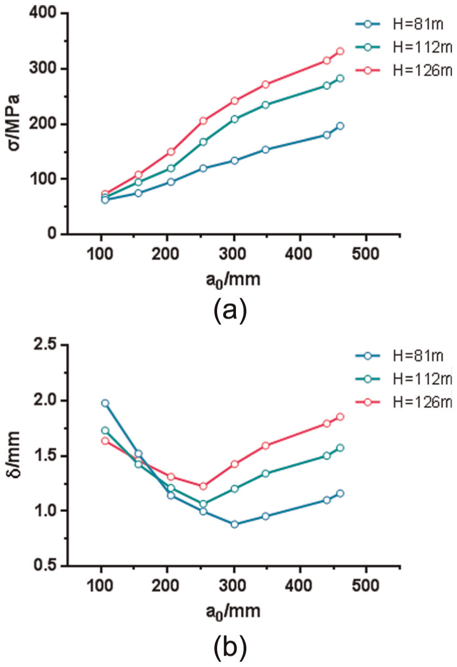
Maximal stress and total deformation of runner at different operating conditions: (a) the curve of maximum equivalent stress versus guide vane opening and (b) the curve of maximum deformation and the mobile guide vane opening.
When the runner intensity is checked, the safety factor of ZG20SiMn nb is 3, the yield strength σs is 295 MPa, and the allowable stress (σ) is σs/nb, 98.3 MPa. It can be seen that under most operating conditions, the Francis turbine runner cannot satisfy the strength requirements. The reliability of the runner is low. The maximum equivalent stress of the maximum head under big guide vane opening exceeds the yield strength. The position of the maximum equivalent stress is in accordance with the runner cracks in practical production and operation. In practical operation, these operating conditions should be avoided to the utmost for the set.
Conclusion
The maximum equivalent stress of the Francis turbine runner increases with the increase in guide vane opening and the rising of head. When the flow is small, the stress on the blade distributes unevenly and the stress concentration appears on the influent side of the blade near the band, on the effluent side connected to the band, and on the effluent side connected to the runner crown. The maximum stress appears on the influent side of the blade connected to the band. With the increase in the flow, the maximum stress appears on the effluent side of the blade connected to the runner crown.
When the flow is small, the maximum runner deformation first decreases and then increases with the increase in flow. The large deformation area spreads from the middle of the blade influent side to the band. The maximum deformation appears in the minimum or maximum guide vane opening and the minimum deformation appears around the middle guide vane opening.
The maximum equivalent stress of the maximum head under big guide vane opening exceeds the yield strength. In practical operation, these operating conditions should be avoided to the utmost for the set. In the meantime, the stress concentration appears in the blade root under various operating conditions and fatigue failure is common. The effluent side of the blade connected to the runner crown should be thickened and filleted.
Footnotes
Declaration of conflicting interests
All the authors declare that there is no conflict of interests regarding the publication of this article. All the authors do not have a direct financial relation with the commercial identities mentioned in our article that might lead to a conflict of interest for any of the authors.
Funding
The work is financially supported by the State Key Program of National Natural Science of China: 51339005.