
Abstract
Learning from the microstructure of the convex (concave) and ridging (triangle and arc-shaped) shapes of fresh lotus leaves and shark skin, bionic ridging shovels was designed with the characteristics of adhesion and resistance reduction. Ten ridging shovel models were established, and the interaction process with the soil by ANSYS is discussed. Stress analysis results showed that the bionic ridging shovel was more obvious in visbreaking and in the resistance reduction effect. An indoor soil bin experiment with the bionic ridging shovel and the prototype ridging shovel was operated as follows: the ridging resistance of the three types of ridging shovel was tested under the condition of two soil moistures (18.61% and 20.9%) and three different ridging speeds (0.68, 0.87, and 1.11 m/s). In this article, the structure, the mechanism, and their relationship to the functions are discussed. The results of this study will be useful in practical application in the field of agricultural machinery toward practical use and industrialization.
Introduction
Currently, conservation tillage technology is widely used. It is important to select the conservation tillage technology according to the local conditions in different types of farming areas. In dry farming areas of Northeast China, wind is strong in the spring and temperatures are low in the winter; farmland spring drought and wind erosion are relatively serious. To resist the adverse effects of the climatic characters in the dry farming areas of Northeast China, the ridge culture of conservation tillage technology 1 is commonly used.
Ridge culture technology is used to ridge and till regularly, according to a certain width, space, and direction; it is used to plant crops in cultivated ridges. This technology can eliminate soil-hardening deterioration, diminish loose soil, reduce soil bulk density, and increase soil porosity. It is beneficial to soil ventilation, moisture retention, and soil water storage to improve crop growth, yield, and quality.2–4 In recent years, research into ridge culture technology has been conducted on rice, wheat, soybeans, and other crops with very good results. However, during the course of ridge cultivation, soil adhesion to the ridging shovel (RS) is inevitably produced as the contact soil part of the ridging machine contacts oil and slips along the relative interface. 5 This soil adhesion can increase the ridging resistance of the RS. Such adhesion affects ridging quality and efficiency and increases energy consumption, and it can also decrease the wear on the contact soil part of the RS, shorten its lifespan, and allow for earlier scrapping. 6 Therefore, to reduce soil adhesion, a reasonable change in the shape and structure of the RS will greatly improve the working efficiency of agricultural machinery and reduce energy consumption.
The shovel surface shape of the normal RS is mostly a cone whose main line-type element is a straight line. When contacting the soil, the soil-engaging surface in the form of a flat surface, constituted by the straight line-type, interacts with the soil. Its buffer is smaller, but the acting force is larger. Although the wings of the soil-engaging surface can separate the soil to reduce soil accumulation, the wings are constituted by the straight line-type in the form of flat surface, causing the transition of the soil-engaging surface to be uneven. Therefore, the resistance between the shovel surface of the normal RS and the soil is very large, which is contrary to reducing the soil resistance 7 during the ridging process.
Because of the important role played by the RS in farming, in recent decades, scholars from various countries have developed and designed several types of RSs to meet the operational requirements of different planting techniques. Researchers have used a variety of methods to intensely study the problem from different angles.
The farming conditions of several types of RSs were tested in dry soil. The results showed that different types of shovels had a significant effect on the distribution of seed, the soil water content, and the soil bulk density. Thus, the shovel types affected the conditions of crop germination and harvest. 8 A wheat-sowing machine equipped with a cusp RS had the highest rate of emergence, providing the best environment for the seedbed. 9 We conducted an experimental study on the dynamic spatial force characteristics of an RS. An analysis of this study showed the change rule of the forward soil resistance and the vertical soil resistance of the RS. This analysis provided some data for selecting the structural parameters of the RS and for improving the ditching performance. 10 In the comparison and analysis of the performance of the several RSs, it was found that in the relatively wet and soft soil, the double disk RS is the most appropriate. In the relatively dry and hard soil, however, the hoe-RS is more appropriate; the soil disturbance quantity of the hoe-RS is the greatest. 11 In the theoretical research of the disk ridging, shovel ditching components of the seeder, the mechanical model of the interactivity between the soil and the disk is found and simulated. Compared with the experimental data, the reliability of the mathematical model 12 is proved. According to the principle that surface shape modification and surface modification can reduce adhesion and resistance, a multiple knot RS is designed and tested in soil with water content from 12.9% to 28.1%. The towing resistance of the RS increases with the increase in the soil water content. When the soil water content exceeds 22%, the towing resistance of the RS decreases. The towing resistance increases with the increase in the traction speed of the RS and then appears in a downtrend. At the traction speed of 7 km/h, the towing resistance is at the maximum. 13 In the experimental research study of the structure of the tillage sowing ditching shovel and its test system, the ability of soil penetration, the towing resistance, and the shape of the seed ditch were compared to the tillage performance of both the double disk furrower and sharp angled furrower. These results were combined with an actual test situation in China, and it is suggested that the sharp angled furrower is more suitable for use in conservation tillage. 14
Expert scholarly research at home and abroad aims to research several basic types of RSs. The effects of several types of common RSs on the seedbed environment, crop growth, and soil disturbance are compared. A small number of relatively simple studies on the surface structure of RSs have also been reported. At present, there are few articles that examine the great ridging resistance, and these articles concern the research and development of new types of RSs.15–17 However, the research methods of these articles have the guiding effect in designing RSs with high performance and characteristics that reduce adhesion and resistance. Among them, biomimicry, a means of designing the morphology and structure of the soil touching parts to reduce the working resistance of soil to those parts, has been widely studied and has already achieved substantial progress (Figure 1). Using the non-smooth surface part of the dung beetle as the bionic object, the bionic plow and disk plow have been developed and tested to work well to reduce resistance. 18 A bionic, non-smooth bulldozing shovel is 13.1%–32.9% smaller than the common smooth bulldozing shovel, but the bionic research of the surface morphology of the RS has not been reported. Regarding the lines extracted from the wild boar head front first touching the soil muzzle parts as the bionic curves, the bionic RS was developed; 19 compared with the common RS, the drag reduction rate is 18.98%. 20 In other words, microscopic non-smooth geometrically structured surfaces can enhance the inherent hydrophobicity of the surface. Macroscopic non-smooth morphology can effectively reduce the contact area with the soil, limiting the continuous film of water and resulting in drag reduction.

Design process of the bionic ridging shovel.
The future development direction of the bionic RS is as follows:
Surface bionic reshaping. This method uses the structure of living beings that have the visbreaking and resistance reduction effects to combine the contact interface state, the resistance characteristics, and the breaking up performance for when the RS interacts with the soil. This process is used to determine the type of surface structure unit, the shape and dimensions, and the distribution and quantity of the RS to reduce the contact surface between the RS surface and the soil, to make the interface water film discontinuous, or to cause stress concentration to reduce the adhesive resistance, all ultimately achieving the goal of reducing resistance.
Surface bionic modified. This modified process may use the visbreaking material of living beings in nature and combine the physio-chemical state when the RS contacts the soil to determine the bionic material of the RS. Changing the properties of the solid material itself is used to change the adhesive attraction between the RS surface and the soil to reduce the adhesion and resistance. 21
Matrix lightweight. This developmental direction may be used to optimize the structure of the dynamic performance requirements to guarantee the reduction of the quantity of the RS matrix, to reduce the interaction forces between the shovel surface and soil, to reduce the adhesion resistance, and to achieve the visbreaking and resistance reduction effects.
This article uses the surface reshaping bionic method and chooses fresh lotus leaves and sharks as the bionic objects to reduce the resistance force of the RS and to construct the non-smooth bionic shovel wall of the RS. Furthermore, this method is used to conduct a finite element simulation analysis for the RS-soil model, verified by an indoor soil bin experiment, to achieve the best visbreaking and resistance reduction in the bionic RS. A solid theoretical basis is established for the bionics research results in practical application in the field of agricultural machinery toward practical use and industrialization.
Materials and methods
Biomimetic RS geometrically structured parameter selection
Tillage tools affect the shape and size of the soil failure zone and consequently the forces on the blade; therefore, the optimization of the tillage-tool design will help to improve energy efficiency. 22 Nature inspires scientists through its creation of aesthetic functional systems, in which biology meets materials. 23 It is believed that the unique property of the self-cleaning of the lotus leaf is based on surface roughness caused by the micrometer-scale papillae and nanometer-scale tomenta (Figure 2(b) and (c)).23,24 Another famous example is shark skin, which protects its surface against biofouling and reduces drag during swimming at fast speeds. The skin is covered with tiny scales (dermal denticles) shaped like small riblets and aligned in the direction of fluid flow.27,28 In this article, the unique super-hydrophobic or resistance-reducing structures are discussed in biomedical applications for RS design.

(a) Lotus leaf and beads, (b) SEM image of micropapillae presented on the surface of lotus leaf, (c) schematic illustration of micro- and nanostructure of a single micropapilla, (d) fast-swimming shark, (e) scales of a shark, and (f) schematic of the saw tooth and scalloped riblets of the scales
The shark and the fresh lotus leaf are considered to be the bionic objects. By extracting the placoid scale rib structure of the shark skin and the super-hydrophobic microscopic structure of the fresh lotus leaf, the macroscopic, non-smooth surface of the RS surface was structured to achieve the goal of reducing the adhesion between the soil and the bionic RS. The bionic groove structure of the bionic RS is based on the size of the biomimetic model of the shark placoid scale rib structure with the preferable rib structure. The constructed bionic groove, the forms, and the cross-sectional dimensions of the grooves are shown in Table 1. The bionic convex hull (CH) structure is based on the microscopic scale of the front two-dimensional profile of the fresh lotus leaf. The hemispherical CH structure is built by using bionic technology with a 2-mm radius and an 8-mm space between the RS prototype and the groove structure surface. Thus, we designed nine types of different bionic RSs: convex arc (CVA), concave arc (CCA), convex triangle (CVT), and concave triangle (CCT), with and without a CH structure above them, and an RS with CH. The ANSYS models are shown in Figure 3.
Schematic diagrams and dimensional parameters of bionic structures on the ridging shovel.

CVT: bionic convex triangle trough cross section of the ridging shovel; CCT: bionic concave triangle trough cross section of the ridging shovel; CVA: bionic convex arc trough cross section of the ridging shovel; CCA: bionic concave arc trough cross section of the ridging shovel; CH: convex hull.

Models used for ANSYS analysis, where RS is the ordinary ridging shovel.
Finite element formulation
The study of constitutive models of soil belongs to the continuum mechanics field of theory. From the microscopic point of view, soil is filled with air and moisture between soil particles, which causes the soil medium to be discontinuous; however, from the macro point of view, these subtle discontinuous are insignificant, and we can use the basic continuum equations to consider soil problems, such as the force balance equations, constitutive equations of materials, or the relationship between stress and strain. However, soil structure is very complex. Soil will experience elastic deformation and plastic deformation at high stress levels. This elastic–plastic model can simulate the inelastic strain–stress relationship of soil. “Plastic deformation” in elastic–plastic soil theory actually refers to irreversible deformation at the macroscopic level, which includes not only the irreversible deformation caused by the slip or micro-cracks between soil particles but also the unrecoverable elastic deformation caused by the retained residual stress after unloading. In recent years, many elastic–plastic models that depend on the yield criterion, the hardening and softening laws, and the flow rule assumption were proposed, such as the Cambridge model, Lade–Duncan model, Khosla–Wu Cap model, and Drucker–Prager model. The Drucker–Prager elastoplastic model was used in this article. The Drucker–Prager model 29 accounts for the volume expansion due to the yield but does not consider the impact of temperature changes. This model is suitable for concrete, soil, and other granular materials.
The yield function (f) of the Drucker–Prager elastic–perfectly plastic model is as follows 29

where α1 is a parameter dependent on the material properties and geometry of the element; σm is the mean principal stress, σm = 1/3Il = 1/3(σx + σy + σz), kPa;
The material parameters included in equation (1) are evaluated as a function of the soil shear strength coefficients, that is, the soil cohesion and the soil internal friction angle.
Apart from cohesion, the shear force also has to overcome a considerable amount of friction. 25 The maximum shear stress expressed by the Coulomb formula is as follows 30

where τ is the shear stress (kPa), c is the soil cohesion (kPa), σn is the normal stress (kPa), and φ is the angle of the soil internal friction (°).
To study the interaction and sliding characteristics of soil–tool system, Coulomb’s criterion of dry friction is specified at the interface elements. Coulomb stated that the frictional force is proportional to the normal load 30

where fr is the coefficient of friction, F is the tangential force (kN), W is the normal force to the contact surface (kN), and δ is the angle of the surface friction (°).
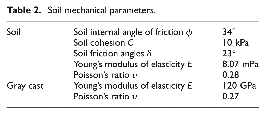
Soil tests were completed to determine the required soil parameter inputs for the structural analysis in ANSYS. Soil cohesion and the coefficients of friction were calculated using equations (1) and (2), respectively. The soil mechanical parameters are shown in Table 2. Solids with 45 nodes, 187 element types, and the Drucker–Prager material model inputs, shown in Table 1, were used for soil meshing.
Soil mechanical parameters.
Accurate modeling of the soil–implement interaction will allow optimization of the implements without performing expensive and time-consuming field tests, which may only be undertaken at certain times of the year. 31 Different modeling methods have been used to model the soil–implement interaction during the tillage process. Studies of the soil–tool interaction have focused on developing force prediction models by using different types of soil, tools, and operating conditions (depth of operation, tool direction, tool geometry, etc.). Some researchers32–35 have experimentally demonstrated that the effects of operating conditions have a great effect on this prediction. In addition, tool shape, size, operating depth, soil physical, and mechanical characteristics also contribute to soil–tool interaction. The models in two dimensions 36 and three dimensions37,38 are the most practical models for analyzing the soil–tool interaction and predicting the forces on tillage blades.
The soil cutting procedure could be observed in two-dimensional or three-dimensional cases, depending on the width and the depth of the cut. The general earth pressure model (equation (4)) first proposed by Reece 39 has been widely used by researchers engaged in predicting soil cutting resistance

where P is the soil drag (kN), γ is the soil unit weight (kN/m3), d is the depth of cut (m), ca is the soil adhesion (kPa), q is the surcharge pressure at the soil surface (kPa), Nγ is the gravity coefficient, Nc is the cohesion coefficient, Nac is the adhesion coefficient, Nq is the surcharge pressure coefficient, and
The three-dimensional model is effective for when the working depth is larger than the width. Based on different hypotheses of the crescent, soil drag has a different algorithm. As in the McKyes–Ali model, one center section and two crescents were considered, as shown in Figure 4. For the side crescents, the surface side failure was assumed to be circular. Using the technique of the mechanics of the equilibrium, soil resistance is expressed as a function of the failure angle β, the soil characteristics, and the tool parameters. 40 A simplified form of this soil resistance is given by the following equation

where α is the rake angle (°), β is the angle of failure plain (°), s = d(cot2β + 2 cot α cot β)1/2, and r = d(cot α + cot β).
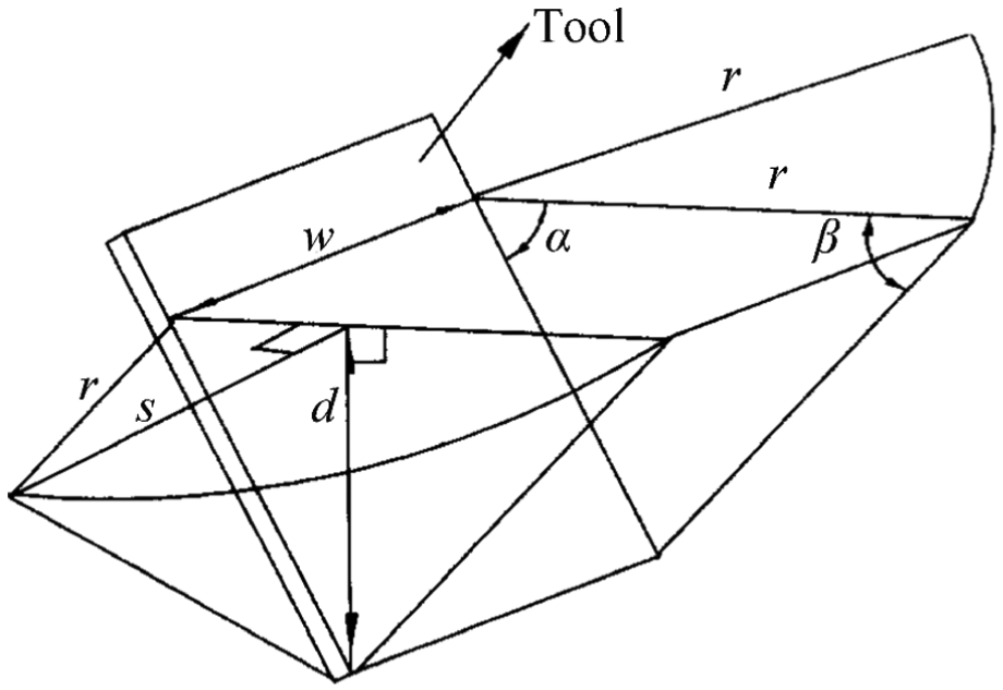
Three-dimensional diagram of the McKyes–Ali model. 37
Considered the moving characteristics of RS, the lateral shear failure impact resistance and cutting resistance were added, equation (5) was changed as given by the following

Because the resulting differential equation is quite complex, it is not practical to obtain the exact solution. Therefore, a trial-and-error procedure was employed to determine the failure angle β. A MATLAB program was developed to identify the value of the failure angle β, which would yield the minimum total soil resistance P.
Results and discussion
Finite element simulation results
The animated results of the simulation in ANSYS for the RS with the conventional surface and nine different bionic RS types are shown in Figure 5.
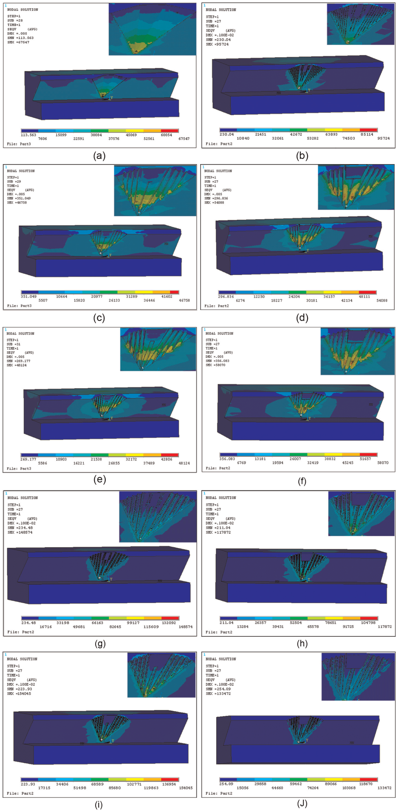
ANSYS results of the 10 models of ridging shovels with conventional surfaces and nine different bionic ridging shovel types: CVA, CCA, CVT, and CCT, with and without a CH structure above them, and an RS with CH): (a) RS, (b) RS–CH, (c) CVT, (d) CCT, (e) CVA, (f) CCA, (g) CVT–CH, (h) CCT–CH, (i) CVA–CH, and (j) CCA–CH.
The interaction between the RS and the soil is a pair of action and reaction forces that reveal the resistance situation of the soil on the RS when the RS interacts with the soil. The pre-processing module of the ANSYS finite element analysis software created and defined the related parameters of the RS prototype, bionic RS model, and the soil model. The stress analysis and calculations were completed when several RSs interacted with the soil. After the analysis, the stress situation of the RS on the soil was verified by the three-dimensional equivalent stress figure, as shown in Figure 6.
Stress analysis results of the ridging shovel prototype and the bionic trough for the convex hull ridging shovel.
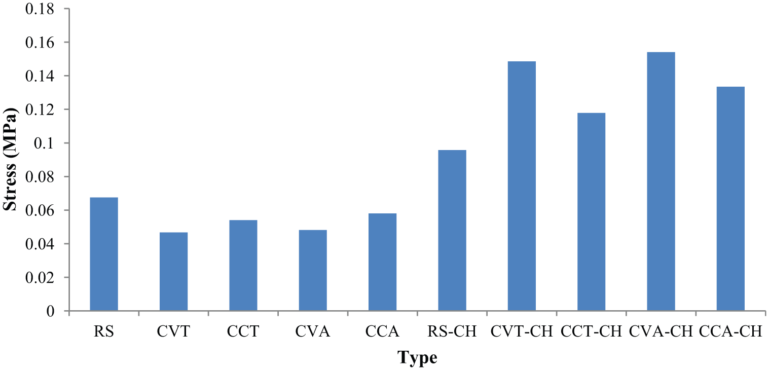
From the distribution and magnitude of the stress, the maximum stress appeared in the tip of the RS prototype and the stress distributed uniformly. The maximum stress of the four types of bionic trough RS appeared in the tip of the bionic trough structure, and the smaller stresses appeared around the bionic trough. Compared to the RS prototype, the stress of the bionic trough RSs has a reduction trend. This trend reveals that the bionic trough RSs break the contact surface between the RS and the soil to a certain degree, the contact between the soil and the RS is then discontinued, and the adhesive force of the soil on the ridging is reduced. The reducing trend of the bionic convex triangular trough RS and the bionic convex arc-shaped trough RS is more obvious. The greater stress area of the two types is apparently smaller than the bionic concave triangular trough RS and the bionic concave arc-shaped trough RS. Taken together, the bionic convex triangular trough RS and the bionic convex arc-shaped trough RS have a more obvious resistance-reducing effect than other shovel types.
Experimental results and soil bin analysis
According to dimensional requirements, the manufacture of the material object of the RS prototype, the bionic convex triangular trough RS, and the bionic convex arc-shaped trough RS is shown in Figure 7.
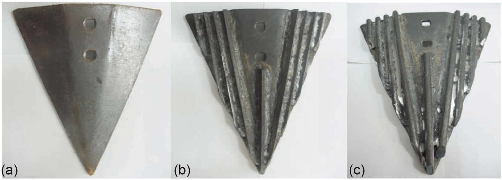
Three types of ridging shovels: (a) RS, (b) CVT, and (c) CVA.
The experimental design is conducted under the condition of two levels of soil moisture (18.61% and 20.9%) and three different ridging speeds (0.68, 0.87, and 1.11 m/s) to test the ridging resistance of the three types of RS (Table 3). Every type of RS is reworked three times at the same ridging speed to achieve the average value of the resistance, which served as the ridging resistance for this type of RS at the specific ridging speed. The changes in ridging resistance for the three types of RSs under the conditions of the three different ridging speeds are compared.
Three types of design tables for the soil grooves of the ridging shovel.

In the experiment, three different ridging speeds are achieved by regulating the soil bin big trolley gear and the speed-tuning knob. The big trolley is regulated at gear 2; the speed-tuning knob is regulated at 6, 8, and 10, corresponding to the forward speed of the big trolley at 0.68, 0.87, and 1.11 m/s. BLR-1 type sensors connect to the soil bin trolley and the RS with its own connection mechanism; the sensor transmits real-time data to the virtual prototype (as shown in Figure 8). After every ridging test, the soil in the experimental area is scarified and leveled off to keep the soil in the same condition.

Ridging shovel sensor connected with a large trolley by a homemade connecting mechanism.
The experimental data were collected and analyzed, and the results are shown in Figure 9. The ridging resistance of the RS has a tendency to increase with the increase in ridging speed and soil moisture. In the condition of the same ridging speed and soil moisture, the ridging resistance of both the bionic convex triangular trough RS and the bionic convex arc-shaped trough RS has a tendency to decrease corresponding to the RS prototype; the decreasing tendency of the bionic convex triangular trough RS is more obvious.

Histogram of the experiment results for three types of ridging shovels (RS, CVT, and CVA) under the conditions of a two water content rates and three types of ridging speeds. MC18.61 is moisture content 18.61% and MC20.90 is moisture content 20.90%.
The bionic RS resistance reduction rates are calculated as (%) = (the ridging resistance of the RS prototype − the ridging resistance of the bionic RS) / the ridging resistance of the RS prototype × 100%. Based on above calculations, the average resistance reduction rate of the bionic convex triangular and convex arc-shaped trough RS is 3.65% and 1.85%, respectively. So it is concluded that the bionic convex triangular trough RS has a more obvious resistance reduction effect than the bionic convex arc-shaped trough RS, which is consistent with the finite element simulation results of the RS and soil model.
Conclusion
CATIA software was used to construct a three-dimension model of the RS and the corresponding soil model in this article. The RS model consists of the RS prototype, the bionic convex (concave) triangular trough RS, and the bionic convex (concave) arc-shaped trough RS. The finite element analysis software was used to simulate and analyze the interaction process of the five RS models and the soil model. The model was also used to explore and compare the stress analysis results to achieve the shovel wall–type structure of the bionic RS, something that is more obvious in the visbreaking and resistance reduction effect. Finite element analysis shows that the bionic convex triangular trough RS and the bionic convex arc-shaped trough RS have more obvious resistance reduction effects than other types of shovel. The indoor soil bin experiment with the bionic RS and the prototype RS were completed. The ridging resistance of the three types of RS was tested, under the condition of two soil moistures (18.61% and 20.9%) and three different ridging speeds (0.68, 0.87, and 1.11 m/s). The average resistance reduction rate of the bionic convex triangular trough RS is 3.65% and that of the bionic convex arc-shaped trough RS is 1.85%, so it is concluded that the bionic convex triangular trough RS has a more obvious resistance reduction effect than the bionic convex arc-shaped trough RS. These conclusions are consistent with the finite element simulation results of the RS and soil model.
Footnotes
Declaration of conflicting interests
The authors declare that there is no conflict of interest.
Funding
This work was supported by National Natural Science Foundation of China (no. 31172144); National Science & Technology Pillar Program of China in the Twelfth Five-year Plan Period (no. 2014BAD06B03); the Science & Technology Development Projects of Jilin Province (no. 201303040NY); the Basic Operation Foundation of Jilin University (no. 201200007); Open Foundation of Key Laboratory of Bionics Engineering, Jilin University, Ministry of Education (no. K201205A); and “Project 985” of Jilin University.