
Abstract
A backward-facing step flow in the microchannel with external electric field was investigated numerically by a high-order accuracy upwind compact difference scheme in this work. The Poisson–Boltzmann and Navier–Stokes equations were computed by the high-order scheme, and the results confirmed the ability of the new solver in simulation of micro-scale electric double layer effects. The flow fields were displayed for different Reynolds numbers; the positions of the vortex saddle point of model with external electric field and model without external electric field were compared. The average velocity increases linearly with the electric field intensity; however, the Joule heating effects cannot be neglected when the electric field intensity increases to a certain level.
Keywords
Introduction
With the development of micro- and nano-technology in recent years, the study on electric double layer (EDL) is changing from theoretical analysis to applied research. The rapid development of micro-fabrication technology has enabled a variety of microfluidic systems, consisting of the microchannel, micro-valves, micro-pumps, and micro-mixer, which have been effectively used in medical, pharmaceutical, defense, and environmental monitoring. The micro- and nano-electroosmotic flow is thus enabled to become a cutting-edge research topic. In microfluidic systems, the electrolyte solution under an applied electric field is driven by the Coulomb force, and the internal liquid molecules start to move; the EDL effect appears on the solid–liquid interface. 1 The rapid development of microfluidic technologies has got a large number of achievements, such as microelectric mechanics systems (MEMS), Biochips, and biosensor systems.2–5 This requires people to have profound understanding of physical characteristics of microfluidic systems so as to manufacture new devices and expand the usage.
Due to the restrictions of geometry size, it is difficult to measure electroosmotic transport phenomena of microchannel flows precisely by experimental methods; therefore, efficient and high-order accuracy numerical scheme of the electroosmotic flow is important in numerical simulation. Over the last few decades, many researches have been done on electroosmotic transport phenomena in microchannels. Hunter 6 reported that the flow behavior will be greatly affected by the close channel surface because of the existence of EDL. Bier et al. 7 used a computer to simulate the electrophoresis of the sample transfer process. In recent years, researchers have employed different numerical methods, such as the finite difference method, 8 finite volume method, 9 and finite element method, 10 to simulate the electroosmotic phenomenon in microchannels with different structures. For pressure-driven flows in microchannels, Wang and Wu 11 reported that the periodical flow velocity and the Flow-Induced Electric Field (FIEF) strongly depend on the frequency Reynolds number; Ban et al. 12 reported that average electric conductivity of electrolyte inside the channel increased significantly as the EDL overlaps. Zhu et al.13,14 demonstrated a model to investigate the transient heat and liquid moisture transfer through porous fibrous media with consideration of EDL. On the shape of microchannels, Taylor et al. 15 studied the impact of surface roughness on fluid flow, and pointed out that with the decrease of channel-scale, the roughness on fluid flow becomes more important. However, the influence of protrusions in microchannels needs to be further investigated with detailed examination of electric conductivity of the electrolyte in order to establish a better understanding of the effect of EDL.
By using a high-order accuracy upwind compact difference scheme, the current research focuses on the simulation of the EDL in a microchannel with a backward-facing step. The remaining sections are arranged as follows: section ‘Formulations and modeling’ gives a brief description about the formulas of EDL and the flow field in microchannel. Section ‘Numerical schemes’ describes high-order accuracy numerical schemes. Numerical results and discussions are presented in section ‘Results and discussion’, and conclusions are drawn in section ‘Conclusions’.
Formulations and modeling
EDL effect
In microfluidic systems, the surfaces of the channel walls are polarized to bring electrostatic charge when wall materials are in contact with the electrolyte solution. For example, when a wall made of glass is put in the water, the chemical reaction produces net negative charges. The interaction between ionizing solution and the static charge on the surface of the insulation affects the distribution of ions in the electrolyte solution, and different charged ions gathered near the wall quickly, resulting in the reorganization of the solid–liquid interface near the liquid ion to form a thin liquid with a net charge layer, which is called the EDL.
Figure 1 shows the backward-facing step flow in the microchannel with external electric field. In the microscopic scale, the step can be seen as a small protrusion of the wall. The external electric field is applied to both the upper and lower wall. In microscopic cases, the continuum assumption is still applicable in the liquid flow when electric field is applied.1,16–20 The electrical potential

where

where

A microchannel with a backward-facing step.
For the symmetric binary electrolyte solution used in this work, the Poisson–Boltzmann equation can be reduced to

Flow field in microchannels
When an electric field is applied at the top and bottom of the microchannel, electrostatic charges in the EDL are driven by the electric force and start to move. The movement of charges drives the movement of liquid within the channel because of the viscosity, thus forming the electroosmotic flow. Because the length of the microchannel is usually much larger than its width, the flows in the microchannel can be well approximated by a fully developed laminar flow except at the entrance and the exit of the channel.
Let
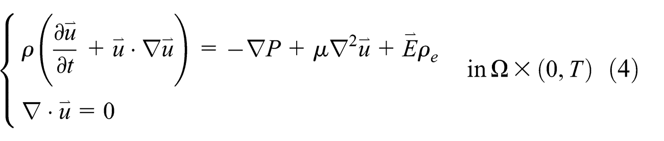
where
Let
where
Let

where

is the Debye–Huckel coefficient and
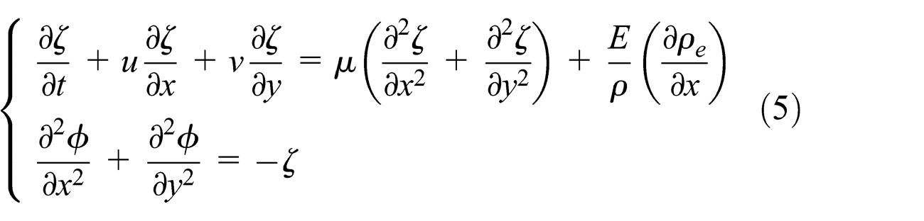
The dimensionless form of equation (3) and equation (5) is

where
The non-slip boundary conditions are

where
Numerical schemes
A fifth-order discretization of the first derivatives
As is known, the general compact differential expression is

In this work, a differential approximation of five points is considered 21

Let

Then equation (11) can be written as

where
The Taylor series of a discrete function
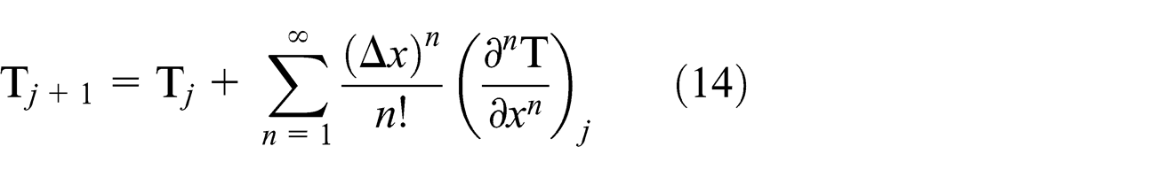
Applying equation (14) to both sides of equation (13) yields
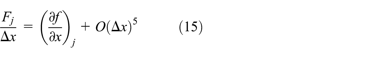
As can be seen,
A fourth-order discretization of the second derivatives
By using Taylor expansion in equation (14), a fourth-order accuracy discretization method for the second derivatives can be written as

Assuming

Substituting (17) into (16) yields

It is noted that
Discretization of the Poisson’s equation
The stream function equations, pressure equation of governing equations are all Poisson’s equations, where

where
Expand
and
then we have

From equation (19),

should be satisfied. Using one of the solutions (e.g.

A relaxation iteration method is employed to solve equation (24) by

Let

In this work, the relaxation factor
Time discretization scheme
A third-order Runge–Kutta method is employed to discretize the temporal space

where
In order to keep the convergence of the iteration,

Results and discussion
In this work, KCl solution is used as the electrolyte solution in the microchannel, and the coefficients are given by Table 1.
The material properties.

The influence of with and without EDL to a backward-facing step model under the high-precision numerical methods was first studied. The strength of electric field applied to the microchannel was 100 kV/m and the potential was 150 mV
By comparing the left and right diagrams of Figures 2 and 3, it can be seen that when Re = 10 and the EDL is applied, the saddle point position of the vortex moves to the left; the location of the vortices tends the backward-facing step and reattachment point of the vortex is closer to the backward-facing step. The length of the recirculation zone is smaller.

Streamline of Re = 10 (left: no EDL; right: with EDL).
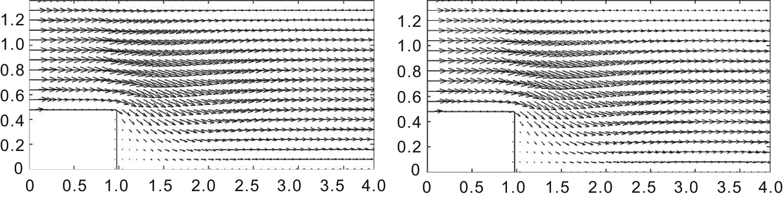
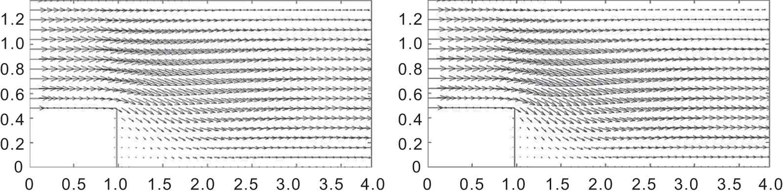
Velocity vectors of Re = 10 (left: no EDL; right: with EDL).
Second, a higher Reynolds number was applied. As can be seen from Figures 4 and 5, when Re = 15 is applied, the trend of fluid motion is more clear; the vortex produced by the backward-facing step is bigger, and the location of the vortex is further from the overall steps. When the EDL is applied, the position of the saddle point moves to the left. Compared with the case of no EDL effects (the left diagram), both the location of the vortices and the reattachment point of the vortex are closer to the backward-facing step. The length of the recirculation zone is smaller.

Streamline of Re = 15 (left: no EDL; right: with EDL).
Velocity vectors of Re = 15 (left: no EDL; right: with EDL).
In order to study the influence of the electric field intensity, the external electric field applied to the microchannel was set to 50, 100, 150, and 200 kV/m; the potential was 150 mV and the Reynolds number was set to 15. Streamlines are given in Figure 6.

Streamlines under different electric field intensities.
In Figure 6, it can be seen that the vortex moves to the left gradually with the increase of the electric field intensity, and the position of the saddle point becomes lower and closer to the step. The flow field moves toward the bottom, and the length of the recirculation zone gets smaller. To further confirm the influence of the external electric field, the relationship between the velocity and the strength of the electric filed is a concern, as is shown in Figure 7.

The average velocity at the outlet versus the electric field intensity.
Figure 7 shows the relationship between the electric field intensity and the average velocity at the outlet. It can be seen with the increase of the electric field intensity that the speed increases linearly. It also should be noted that the electric field strength cannot increase indefinitely because once the field strength increases to a certain value, the Joule heating effects will too obviously be neglected.
Conclusion
Based on a high-accuracy upwind compact difference method, the Navier–Stokes equations of vortex-stream form and the Poisson–Boltzmann equation were solved in this work. A backward-facing step flow in the microchannel with external electric field was investigated numerically by the scheme; the results confirmed the ability of the new solver in simulation of micro-scale EDL effects. Several characters of the backward-facing step flow in the microchannel with external electric field are discovered:
In a backward-facing step flow in microchannels, EDL appears and the position of the vortex saddle point moves to the left in the presence of the external electric field. Compared with the case with no EDL effects, both the location of the vortices and the reattachment point of the vortex are closer to the backward-facing step, and the length of the recirculation zone is smaller. With an increase of the Reynolds number, the discrepancy in fluid motion becomes clearer.
The velocity increases linearly with the electric field intensity. However, the electric field intensity cannot increase indefinitely, as the Joule heating effects will too obviously be neglected when the electric field intensity increases to a certain level.
The computation process and the results show the effectiveness of the method and confirm the ability of the new code to simulate the EDL effect within microchannels. By using the high-order upwind compact scheme, the simulation is more accurate, and to confirm this is a future job for us.
Footnotes
Acknowledgements
The authors would like to thank Miss Liao Wen for the numerical examples. This work was supported by the National Science Foundation of China (NSFC), Grant 91230114, 11202248, and the China Postdoctoral Science Foundation, Grant 2012M521646.
Declaration of conflicting interests
The authors declare that there is no conflict of interests regarding the publishing of this article.