
Abstract
At present, the motion characteristics of the drilling robot have not been studied in detail. So, the control of weight on bit (WOB) and rate of penetration (ROP) the drilling robot lacks theoretical basis. The control of WOB and ROP of the drilling robot is either severely delayed or uncontrollable. A motion model with load of the drilling robot was established. Analyzed the motion characteristics of the drilling robot based on the motion model through simulation. On the basis, the univariate control model and multivariable control model of the drilling robot based on the load sensitive principle were established. Analyzed the control response law of the univariate control model and multivariable control model of the drilling robot trough the simulation of control models. Results shows that the main factor determining the motion characteristics of the drilling robot is the distribution of flowrate. Quantitative results show that the multivariable control model achieved a fluctuation attenuation rate exceeding 95% and regulated WOB with a precise sensitivity of approximately 0.7 l/min per bar, proving superior to the univariate model in maintaining stable downhole operations. The univariate control model and multivariable control model of the drilling robot can effectively control WOB and ROP. The proposed univariate control model and multivariable control model of the drilling robot can provide reference and basis for the development of controlled algorithm of drilling robot.
Keywords
Introduction
In the oil industry, the horizontal well is one of the most important well types in downhole engineering. 1 The horizontal well has become the main technology of construction for exploitation of oil and gas. The technology of horizontal well is considered to be the most important innovation in drilling. Over the past four decades, the horizontal well has been widely implemented. 2 In 2012, more than 2300 horizontal wells were drilled in China. In the drilling engineering of horizontal well, the drilling technology of the horizontal well of coiled tubing is gradually maturing. The drilling technology of the horizontal well of coiled tubing has many advantages, such as low cost, low pollution, and easy to achieve automation and intelligence.3–5 However, the drilling technology of the horizontal well of coiled tubing encounters many challenges in actual operations. In horizontal wells, the drilling string of coiled tubing is prone to buckling locking. Livescu and Craig have proposed to use the techniques for reducing friction to extend the length of tubing in horizontal wells. 6 However, the drilling depth of coiled tubing is still limited. At present, the drilling robot is mostly used to solve the above problems in the oil industry. The downhole drilling robot can provide axial traction to overcome the resistance of friction. According to modes of movement, the downhole robot is mainly divided into the downhole telescopic robot, the downhole wheeled robot and the downhole crawler robot.7,8 According to the investigation of existing researches, it is found that only the downhole telescopic robot can meet the needs of drilling of coiled tubing.9–11 Downhole telescopic drilling robot will encounter many challenges in operation. The motion of a drilling robot is achieved by one complete motion cycle. The telescopic drilling robot achieves the movement of the drilling robot through the crossed movement of the front and rear traction mechanisms. 12 There are many factors that affect the motion cycle of the drilling robot. Weight on bit (WOB) and rate of penetration (ROP) of the drilling robot are strongly influenced by the fluctuation of pressure and the fluctuation of flowrate in the hydraulic system of the drilling robot. During the drilling process of the drilling robot, the change of load of drilling tool causes the drastic change of the pressure in the telescopic cylinder. The drastic change of pressure in the telescopic cylinder causes damage to the valve body and the cylinder body. And the fluctuation of flowrate caused by the fluctuation of pressure makes weight on bit (WOB) and rate of penetration (ROP) unstable during the drilling process. Or due to the fluctuation of pressure and the fluctuation of flowrate of the source of drilling fluid, the fluctuation of pressure and the fluctuation of flowrate entering the telescopic cylinder is caused. The fluctuation of the WOB and ROP caused by the fluctuation of pressure and the fluctuation of flowrate in the telescopic cylinder leads to the damage of the drilling bit and drilling tool.
Based on the above problems, the simulation models of motion of the drilling robot were established. The load sensitive loops combining the constant pressure difference valve and the throttle valve were proposed. The flowrate of drilling fluid entering each cylinder body and bottom hole assembly (BHA) of the drilling robot and the pressure difference between the inside and outside of the robot were controlled by the load sensitive loops. The motion models and control models of drilling robot were built. The characteristics of motion of the drilling robot were analyzed. And the main control factors of the motion cycle of the drilling robot were revealed. The changes of WOB and ROP of drilling robot under different control models were analyzed. The multivariable laws of variation of WOB and ROP were obtained, which provide reference and basis for the development of controlled algorithm of drilling robot. The remainder of this paper is organized as follows: Section 2 establishes the kinematic and hydraulic sub models of the robot. Section 3 quantitatively analyzes the WOB and ROP response laws of the univariate and multivariable control models. Section 4 concludes the paper and discusses future works.
Study on motion characteristics of the drilling robot
Structural model and motion principle of the drilling robot
The scheme of coiled tubing string based on the drilling robot is shown in Figure 1(a). The drilling robot drags the coiled tubing in vertical section well, build section well and horizontal section well. The BHA of the drilling robot is shown in Figure 1(b). As can be seen in Figure 1(b), the drilling robot drags the coiled tubing and provides WOB and ROP for the drilling bit. 13 Based on principle of the coiled tubing downhole robot, the overall structure of the drilling robot was built. The overall structure of the drilling robot is composed of upper joint, rear traction mechanism, control section, front traction structure and lower joint. The overall design structure of the drilling robot is shown in Figure 2. Based on this design, a physical prototype of the drilling robot was manufactured to verify the structural feasibility and assembly logic, as shown in Figure 2(b). The movement of the drilling robot is achieved by one complete motion cycle. The drilling robot achieves the movement of the drilling robot through the crossed movement of the front and rear traction mechanisms. The movement of the drilling robot is periodic. The principle of movement of a motion cycle of the drilling robot is divided into seven steps. The principle of movement of a motion cycle of the drilling robot during drilling is shown in Figure 3. As illustrated in Figure 3, the traction system mainly consists of front and rear support cylinders (for anchoring) and front and rear telescopic cylinders (for stroking). During a typical cycle, the rear support claws anchor against the borehole wall to provide a stable base, while the rear telescopic cylinder extends to push the front section and the drilling bit forward. Subsequently, the front support claws anchor the borehole wall, allowing the rear section to retract. This strictly alternating anchoring and extending logic, which is controlled by the sequential switching of high and low fluid pressures in the cylinder cavities, enables the continuous ‘inchworm’ movement of the drilling robot.
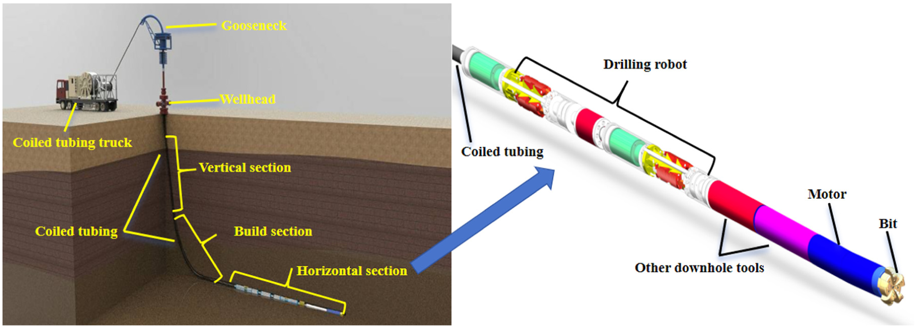
Drilling assembly of the drilling robot: (a) 3D design model and (b) manufactured physical prototype.
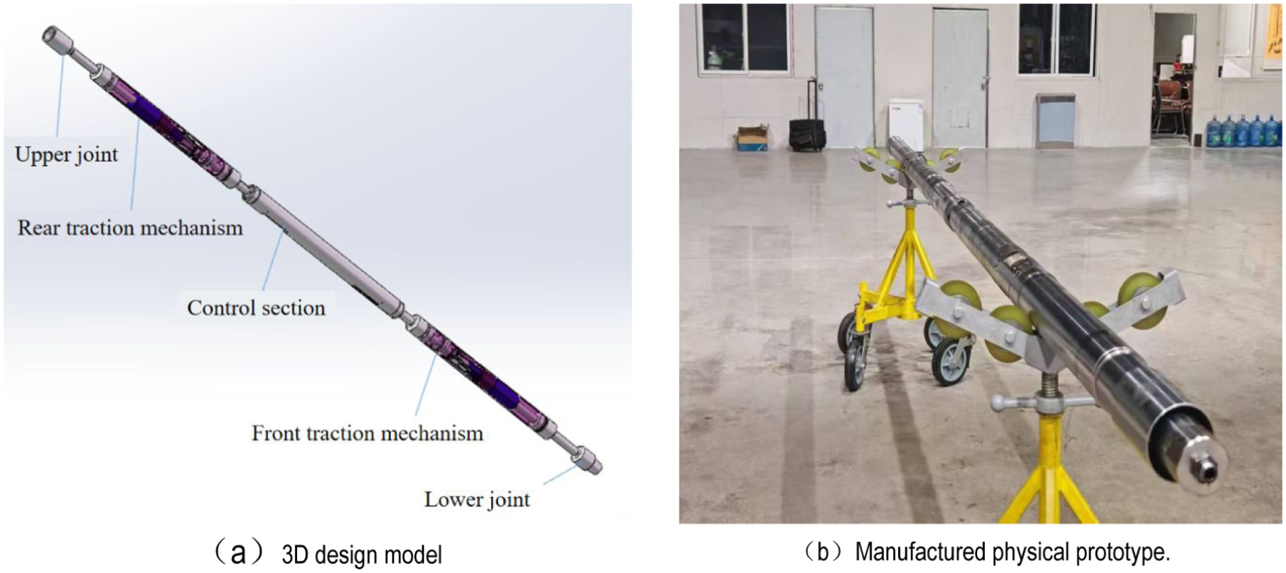
The overall structure of the drilling robot: (a) 3D design model and (b) Manufactured physical prototype.
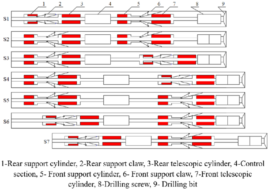
The principle of movement of a motion cycle of the drilling robot during drilling.
Motion models of the drilling robot
(1) Analysis of model of motion logic.
The main motion cylinders are composed of two groups of cylinders, which are the front support cylinder, the front telescopic cylinder, the rear support cylinder and the rear telescopic cylinder. The four blocks of cylinders (i.e. the left and right cavities of the front and rear support cylinders, and the left and right cavities of the front and rear telescopic cylinders, as illustrated in Figure 3) can be divided into eight cavities of cylinders. Depending on the orderly commutation of the reversing valve, the cavities of high and low pressure of the eight cavities of cylinders change orderly. The logic of change of high and low pressure in the cylinder is the key to the models of motion of the whole drilling robot. The motion cycle of the drilling robot is achieved finally.
The cyclic logic of the high and low pressure of hydraulic cavities of the drilling robot is shown in Table 1. Each row represents a stage of motion cycle. Each column represents the state of high and low pressure of the hydraulic cavity in this stage. 1 represents that the hydraulic cavity is currently in high pressure, 0 represents that the hydraulic cavity is currently in low pressure. According to the law of change of the above hydraulic cavities, the motion logic of each reversing valve can be obtained. To illustrate how to interpret the logic matrices, consider ‘Cycle position 0’ as an example. In Table 1, the rear support cylinder’s left cavity is ‘1’ (high pressure) and right is ‘0’ (low pressure), meaning the rear mechanism is anchored. Simultaneously, the front telescopic cylinder’s right cavity is ‘1’, meaning it pushes forward to drill. Table 2 translates these states into electrical signals (e.g. 40/−40 mA) required to shift the electromagnetic reversing valves.
Logic table of high and low pressure of each hydraulic cavity.
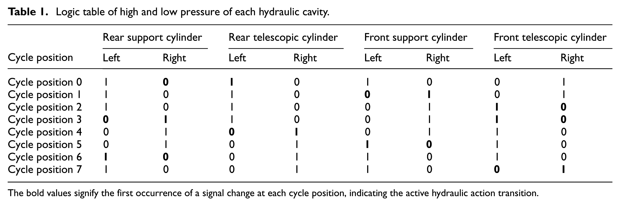
The bold values signify the first occurrence of a signal change at each cycle position, indicating the active hydraulic action transition.
Logic table of switching of hydraulic reversing valve.
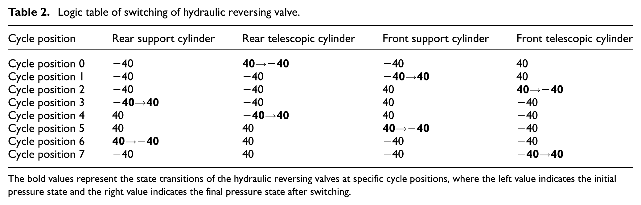
The bold values represent the state transitions of the hydraulic reversing valves at specific cycle positions, where the left value indicates the initial pressure state and the right value indicates the final pressure state after switching.
The motion logic of each hydraulic reversing valve can be obtained from Table 1, which is shown in Table 2. The electromagnetic reversing valves were used. According to the definition of current and orientation of the electromagnetic reversing valve, when the electromagnetic reversing valve was energized by −40 mA, the electromagnetic reversing valve worked on the left side. And when the electromagnetic reversing valve was energized by 40 mA, the electromagnetic reversing valve worked on the right side. As shown in Table 2, in each cycle position, the electromagnetic reversing valve moved. Each electromagnetic reversing valve had a switching of complete position.
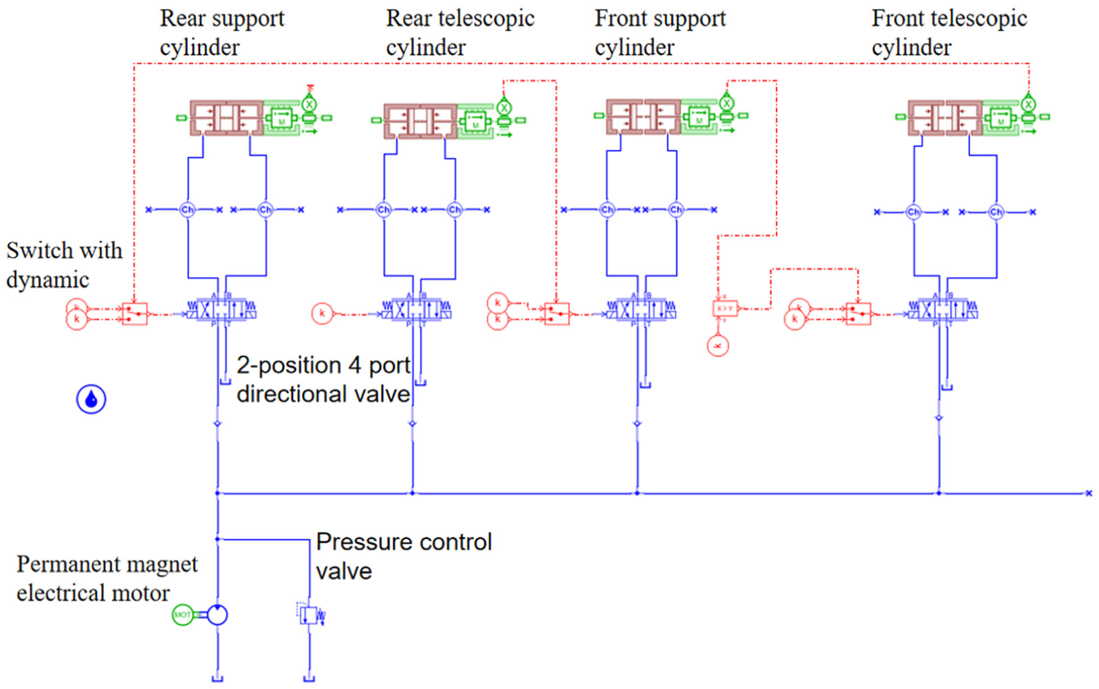
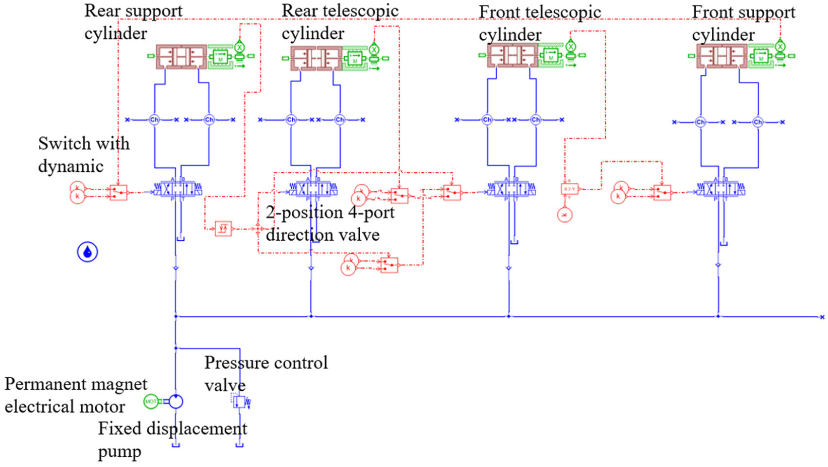
The systematic modeling and kinematic characteristic analysis of the drilling robot were performed using the Siemens Simcenter Amesim simulation platform. Unlike conventional hydraulic systems, the drilling robot requires strict adherence to the sequential logic of high and low-pressure switching across eight hydraulic cavities (as detailed in Tables 1 and 2). Standard hydraulic library components were insufficient to fully replicate this complex ‘inchworm’ motion logic. Therefore, custom sub models were developed by integrating the Hydraulic Component Design (HCD) library with the Signal Control library. A dedicated logic control loop was designed to translate the discrete cyclic states defined in Table 2 into continuous real-time control signals for the electromagnetic reversing valves. This custom modeling approach, illustrated in the connection between the signal loops and hydraulic components in Figure 4, ensures that the simulation accurately captures the dynamic coupling between the hydraulic pressure fluctuations and the mechanical step-wise motion. The composition of the motion model is described in detail below. To ensure the reproducibility and physical accuracy of the custom sub models, the foundational mathematical relationships of the hydraulic valves and cylinders were established using the Hydraulic Component Design (HCD) library. The dynamic behavior of the fluid passing through the reversing valves is governed by the standard Bernoulli orifice flow equation:
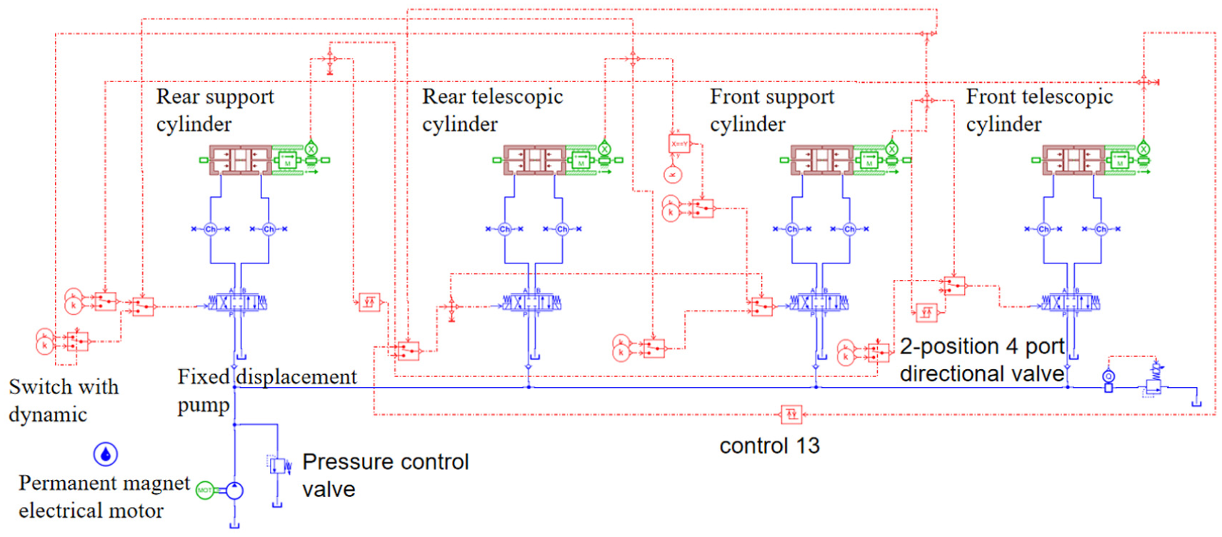
The motion model of the drilling robot.
The main components of the model of hydraulic system of the drilling robot include: the motion cylinders, the electromagnetic reversing valves, the simulated source of drilling fluid composes of fixed displacement pump and motor. According to the above motion logic, the judgment of signal logic and constant signal were used in turn to form the loop of signal from the cycle position 0 to the cycle position 3. After the previous motion reached the structural setting value, the rear telescopic cylinder, the front telescopic cylinder and the front support cylinder successively switched the station of the reversing valve.
After the cycle position 3 (the rear support cylinder moved to the left to 0 m), the rear telescopic cylinder moved to the left. At this time, the output signal of the rear support cylinder was transmitted to the rear telescopic cylinder. It affected the movement of the front support cylinder. Therefore, the trigger and multiple judgments were used after the cycle position 4 to achieve the independent movement of the rear support cylinder.
The diagram of loop of control and judgment of the cycle position 4 is shown in Figure 5. The statement of judgment to be made at this step is:
When signal 1 outputs 40, the front telescopic cylinder executes signal 2 and outputs 40 to the front telescopic cylinder.
When the output of signal 1 is −40, the front telescopic cylinder executes signal 3, and signal 3 continues to judge.
When the displacement of the rear telescopic cylinder reaches 0.2 m, the signal 3 outputs 40, and this step is step 1.
When the displacement of the rear telescopic cylinder is less than 0.2 m, the signal 3 outputs negative 40, this step is the starting point.
The diagram of loop of control and judgment of the cycle position 4.
Similarly, the motion judgment of the remaining cycle steps can be established.
(2) Structural parameters of motion model of drilling robot
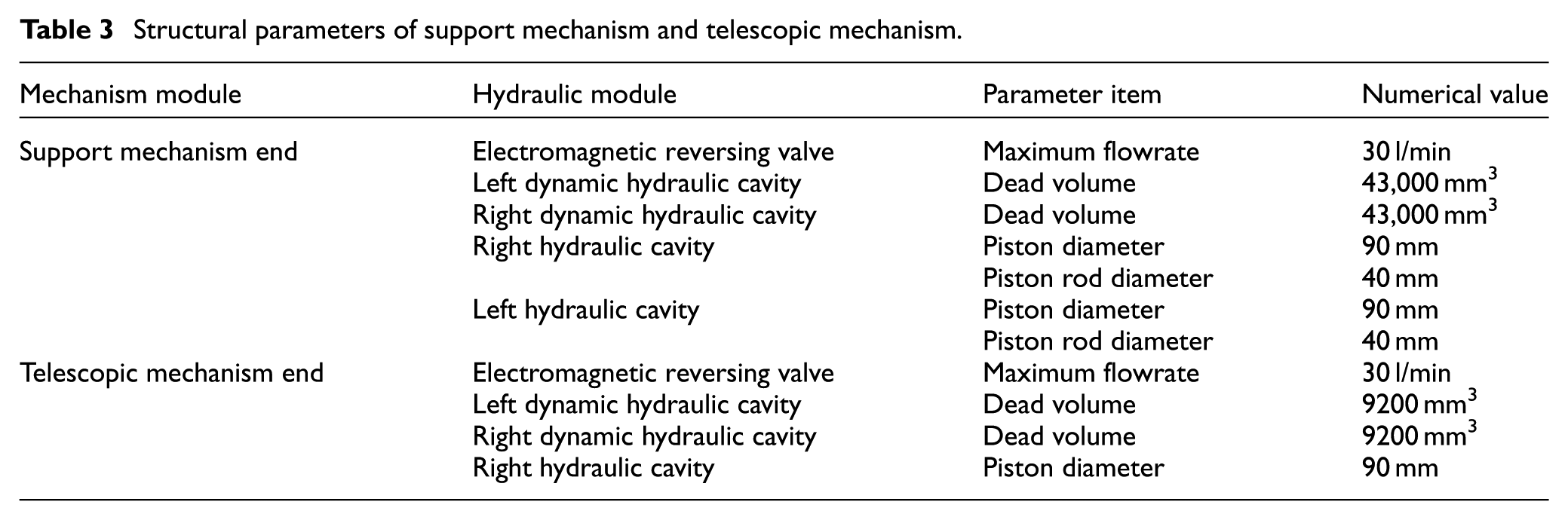
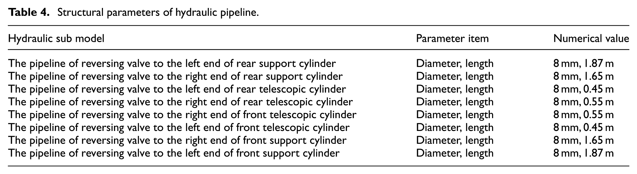
The structural parameters of the support cylinders and the telescopic cylinders are shown in Table 3. In addition, according to the actual situation of each valve group and flow channel, the parameters of hydraulic pipeline in Figure 6 are shown in Table 4.
(3) Sub model of load of support mechanism
Structural parameters of support mechanism and telescopic mechanism.
The motion model of the first four cyclic positions.
Structural parameters of hydraulic pipeline.
The movement of the support mechanism is driven by the liquid inlet of the left and right hydraulic cavity’s of the support cylinder to push the support arm to move, so expand outward to tighten the shaft wall or recover. The support mechanism has the advantages of reliable support and saving axial length under the conditions of same well diameter adaptation.
The support cylinder drives the support mechanism to contact the shaft wall. The shaft wall is assumed to be rigid by default. And the deformation of the support mechanism after contacting the shaft wall is not considered. The support cylinder contacts the shaft wall after passing an empty stroke S1. And the external load is very small before contacting the shaft wall. According to the relationship between the output value S2 and S1 of the displacement sensor, the output function of force-f(s) is obtained. And the load force of the support cylinder is simulated. The sub model of support mechanism is shown in Figure 7.
(4) Sub model of load of telescopic mechanism
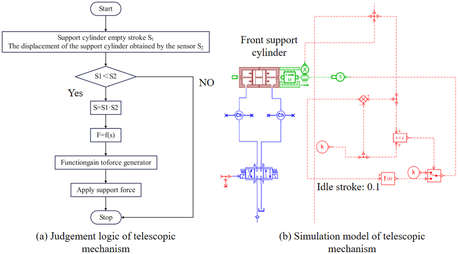
Sub model of support mechanism: (a) Judgement logic of telescopic mechanism and (b) Simulation model of telescopic mechanism.
According to the motion logic, the telescopic cylinder in the telescopic mechanism needs to drive the drill pipe when the telescopic cylinder moves forward. Therefore, the model of the telescopic cylinder introduces the traction force. When the reversing valve works in the right position, the force generator applies the traction force. In this paper, the preset traction force is 10,000 N. The sub model of telescopic mechanism is shown in Figure 8.
(5) Remaining sub models
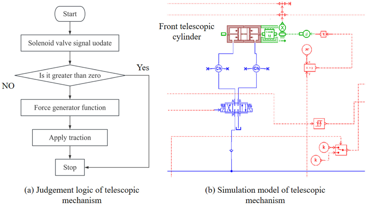
Sub model of telescopic mechanism: (a) Judgement logic of telescopic mechanism and (b) Simulation model of telescopic mechanism.
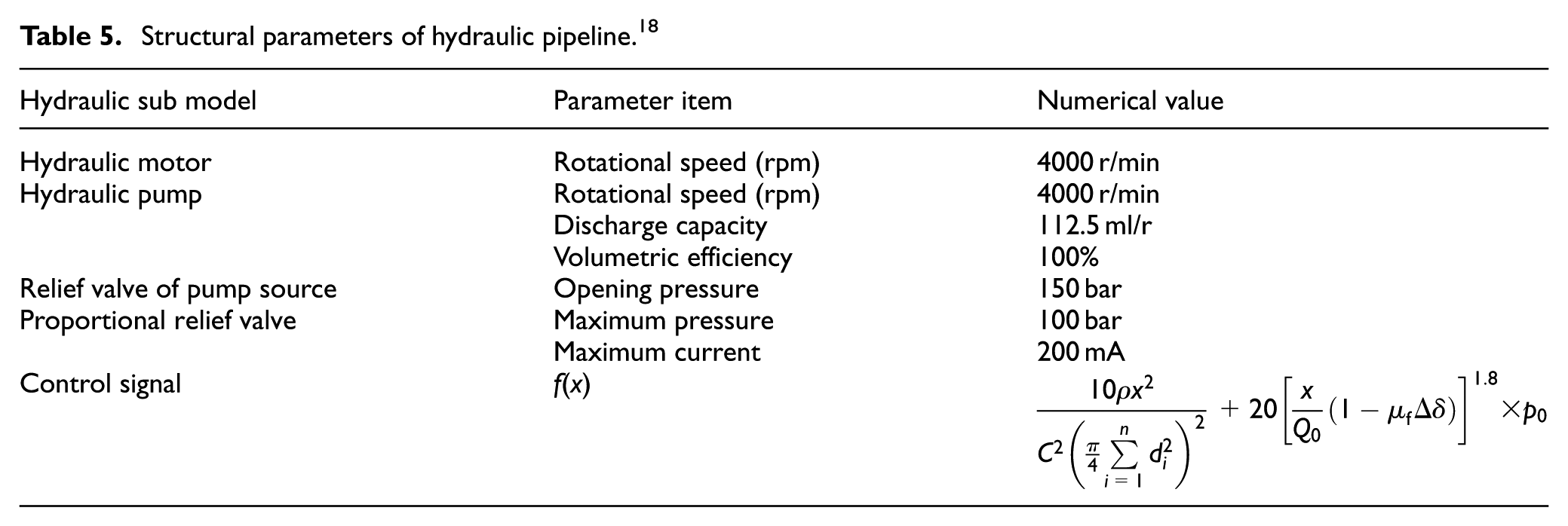
In the simulation model of the drilling robot, in order to simulate the consumption of flowrate of drilling screw and drill bit, the sub models of drilling screw and drill bit were established. As well as the central pipe of flow and simulated mud pump were established. The remaining sub models are shown in Figure 9. The remaining hydraulic parameters of sub models are shown in Table 5.
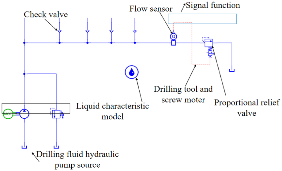
Remaining sub models.
Structural parameters of hydraulic pipeline. 18
Motion characteristics of the drilling robot
There are many factors affecting the motion characteristics of the drilling robot. The structural size is a very important factor. According to the general law of downhole tools and previous studies, it can be seen that the load traction and the density of drilling fluid have an effect on the motion cycle of the drilling robot. However, the change is not obvious. According to the above modeling and analysis of each part of the drilling robot, a complete model of motion characteristic of load of the drilling robot was built. The influencing factors on the motion characteristics of the drilling robot were comprehensively analyzed. The major influencing factors on the motion cycle of the drilling robot.
(1) Analysis of motion cycle of the drilling robot
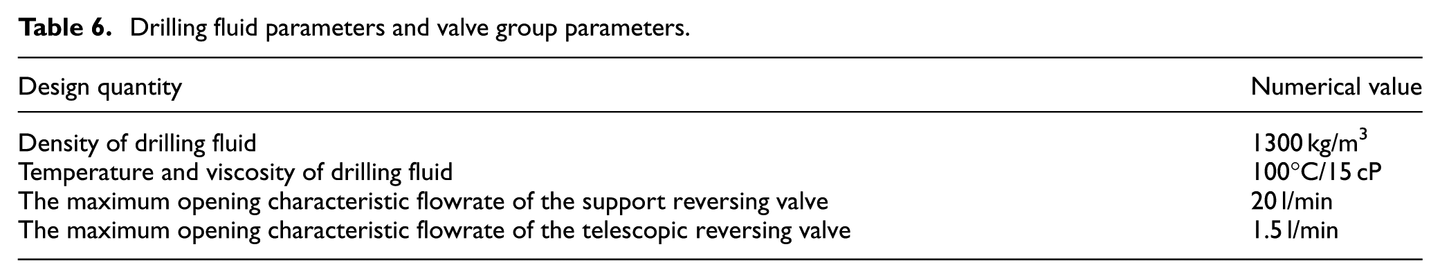
The final model of motion of drilling traction (include load) using the above sub models is shown in Figure 10. The parameters of drilling fluid and valve group are shown in Table 6. Under the conditions of drilling fluid displacement of 7.5 l/s, traction of 12,000 N and borehole diameter of 142.9 mm, the parameters from Table 3 to Table 6 were substituted into the model. The diagrams of motion cycle of the drilling robot are shown in Figures 11 to 13. It can be seen form Figures 11 to 13 that:

Load motion model of the drilling robot.
Drilling fluid parameters and valve group parameters.
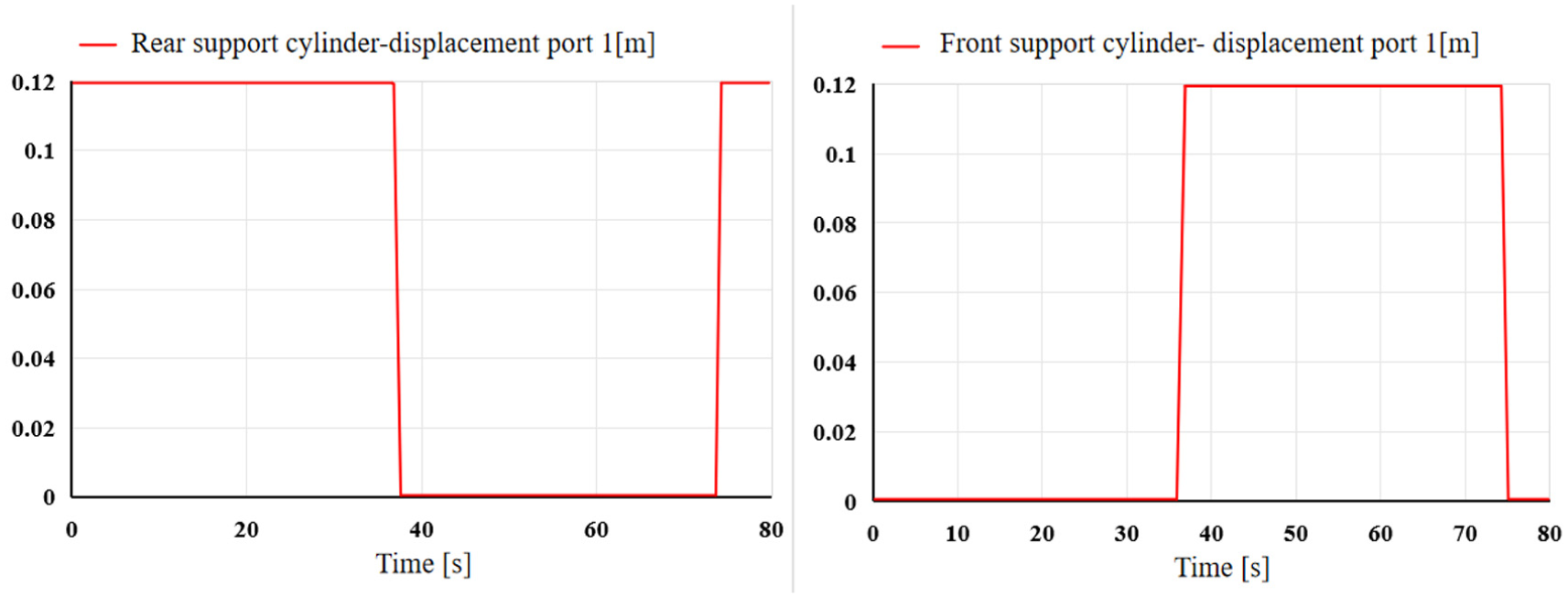
Motion cycle diagram of support cylinder.
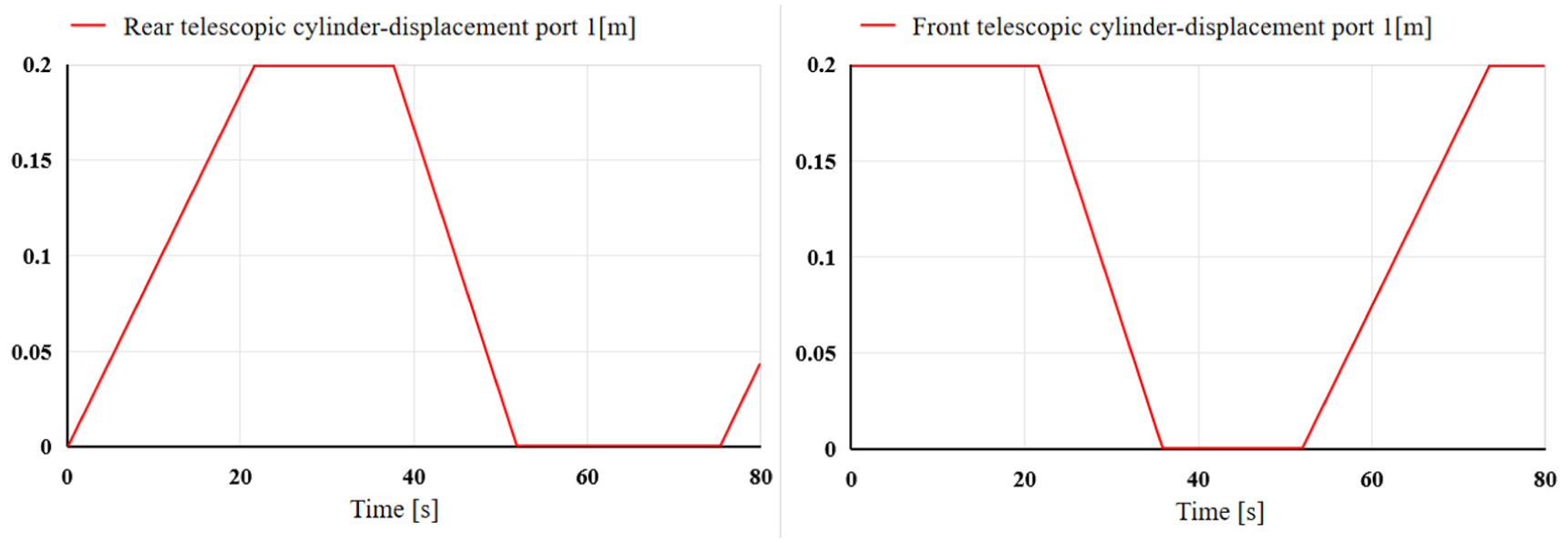
Motion cycle diagram of telescopic cylinder.
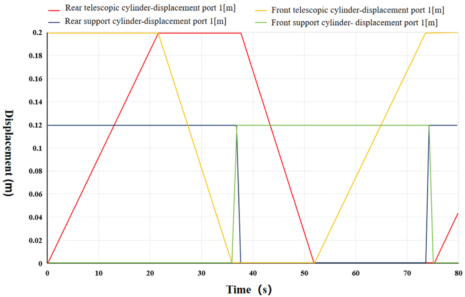
The overall motion cycle diagram of drilling robot.
Figure 11 shows that the front and rear support cylinders of the drilling robot have the same motion cycle. Figure 12 shows that the front and rear telescopic cylinders of the drilling robot have the same motion cycle. Figure 13 indicates that the complete motion cycle of the drilling robot is about 75.15 s. The drilling robot moved forward 0.4 m, as indicated by the peak displacement of the telescopic cylinder in Figure 13. The motion nodes of the front and rear support cylinders are connected. When the rear support cylinder reaches its maximum displacement and begins to descend, the front support cylinder just moves and reaches its maximum displacement. The front and rear telescopic cylinders have the same law of motion. The above results indicate that the load motion model of the drilling robot is correct. Furthermore, to functionally verify the credibility of the constructed custom sub models, a comparative cross-validation was performed between the theoretical design and the simulation outputs. According to the predefined sequential logic in Tables 1 and 2, the front and rear mechanisms must perform strictly alternating cross-motions. As illustrated in Figures 11 to 13, the simulated displacement curves perfectly replicate this strict alternating logic, with the motion nodes connecting seamlessly. The stable overall motion cycle of 75.15 s serves as a robust functional verification, demonstrating that the custom-built hydraulic-signal coupled sub models correctly capture the complex kinematic characteristics.
(2) The influence of the maximum characteristic flowrate of reversing valve on the movement of drilling robot
The maximum characteristic flowrate of the maximum opening of the reversing valve selected by different cylinders is different. The drilling efficiency and drilling stability of the drilling robot are considered. The telescopic cylinders need to pull and drive the whole downhole string. And the telescopic cylinders provide WOB to drilling bit. The telescopic cylinders need to move smoothly. Therefore, the reversing valves with smaller characteristic flowrate were selected. Meanwhile, the support cylinders selected reversing valves with larger flowrate to increase the support velocity. The flowrate of inlet, linear velocity and kinematic acceleration of the rear telescopic cylinder and rear support cylinder are shown in Figures 14 to 16. It can be seen from Figures 14 to 16 that:
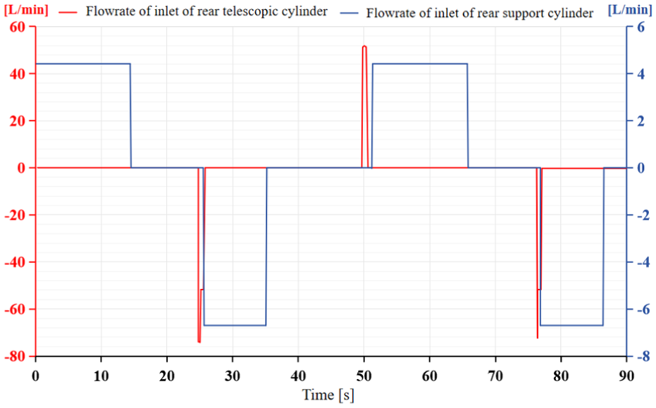
The diagram of flowrate of inlet of rear telescopic cylinder and rear support cylinder.
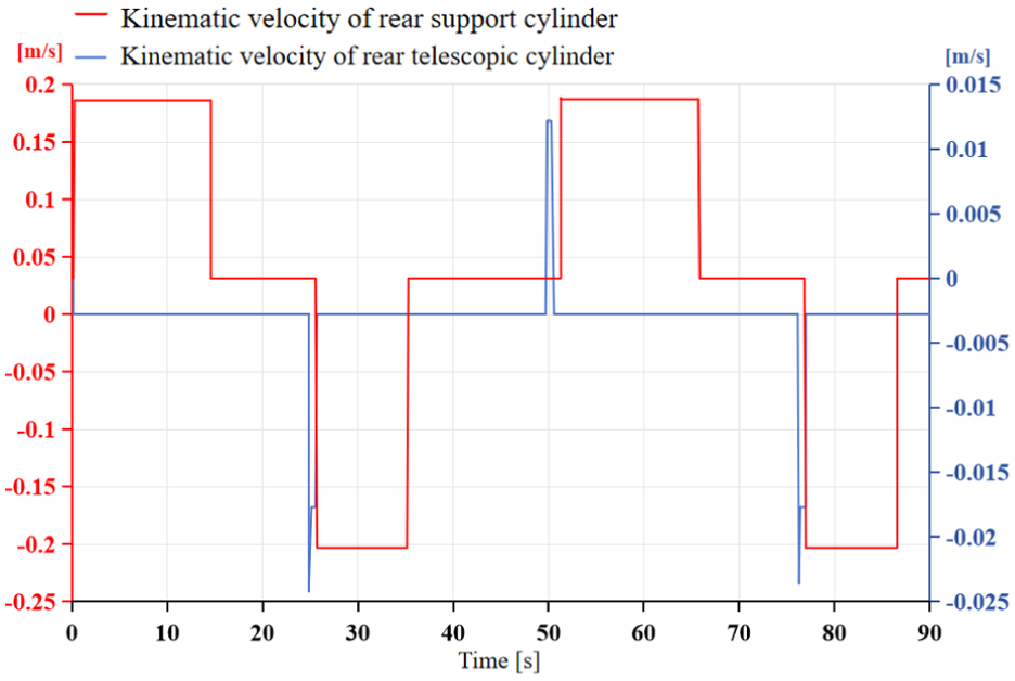
The diagram of linear velocity of rear telescopic cylinder and rear support cylinder.
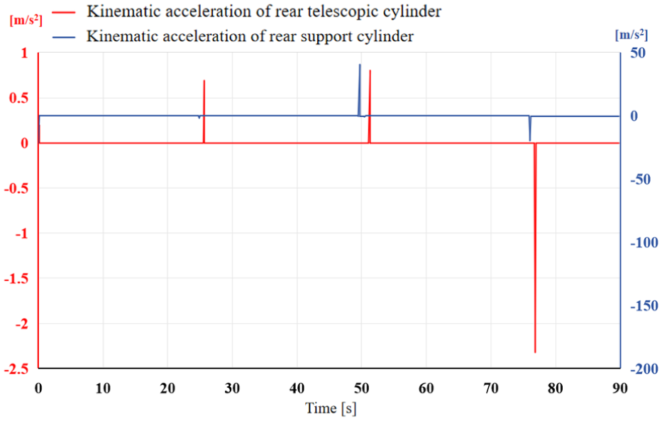
The diagram of kinematic acceleration of rear telescopic cylinder and rear support cylinder.
Figure 14 shows that due to the different characteristic flowrate of the two kind reversing valves, the flowrate of inlet of rear telescopic cylinder and rear support cylinder have a significant difference. The flowrate of inlet of the rear telescopic cylinder is about 4.2 l/min. And the flowrate of inlet during the motion process is basically stable. The peak flowrate of inlet of the rear support cylinder is about 45 l/min. And the flowrate during the motion process was completed and formed in a short time. Figure 15 indicates that the linear velocity difference between the rear telescopic cylinder and rear support cylinder is not obvious. The linear velocity of the rear telescopic cylinder is relatively stable. The rear support cylinder completed the change of linear velocity in a short time. The kinematic velocities of the rear support cylinder and rear telescopic cylinder are asymmetric during the movement. During the supporting process of the support cylinder, the rear support cylinder was gradually affected by the force of wellbore reaction. The supporting process of the rear support cylinder is slower than the process of recovery. The maximum linear velocity is about 0.17 m/s. The process of recovery of rear support cylinder was completed quickly, and the maximum linear velocity is about 0.24 m/s. The rear telescopic cylinder have a same condition. The process of propulsion is slow, and the maximum linear velocity is about 0.13 m/s. The process of recovery is fast, and the maximum linear velocity is about 0.21 m/s. Figure 16 shows that the kinematic accelerations of the rear telescopic cylinder and rear support cylinder occurred when the direction of linear velocity was converted. Therefore, the support cylinder and rear telescopic cylinder were in uniform motion during the movement.
(3) The influence of the characteristic flowrate of reversing valve on the motion cycle
To reveal the mechanism of how flowrate distribution affects the drilling efficiency, an engineering design optimization framework was established. The optimization problem is defined as minimizing the total motion cycle period (T cycle ) to maximize the overall Rate of Penetration (ROP), subject to the hydraulic system’s constraints. 15
The objective function and constraints are defined as follows:
(1) Q<Q max (Limited by the maximum output of the drilling fluid source, 30 l/min),
(2) Stability Constraint: The telescopic velocity must be limited to ensure stable Weight on Bit (WOB).
A univariate sensitivity analysis was conducted to evaluate the impact of each variable. The parameter ranges were selected based on the operational envelope of the actual hydraulic components:
Support Loop: High flowrate range (16–24 l/min) was selected to minimize the non-drilling time (anchoring and retracting). Telescopic Loop: Low flowrate range (0.5–2 l/min) was selected because the drilling speed is physically limited by the rock breaking process; excessive flow leads to pressure spikes and tool damage.
Keeping the density of drilling fluid, flowrate and other parameters unchanged. Keeping the characteristic flowrate of the reversing valve of the telescopic cylinder 1 l/min unchanged. Adjusting the characteristic flowrate of the reversing valve of the support cylinder from 16 to 24 l/min. The varied relationship between the characteristic flowrate of the reversing valve of the support cylinder and the motion cycle of the drilling robot is shown in Figure 17. Keeping the density of drilling fluid, flowrate and other parameters unchanged. Keeping the characteristic flowrate of the reversing valve of the support cylinder 20 l/min unchanged. Adjusting the characteristic flowrate of the reversing valve of the telescopic cylinder from 0.5 to 2 l/min. The varied relationship between the characteristic flowrate of the reversing valve of the telescopic cylinder and the motion cycle of the drilling robot is shown in Figure 18. It can be seen from Figures 17 and 18:
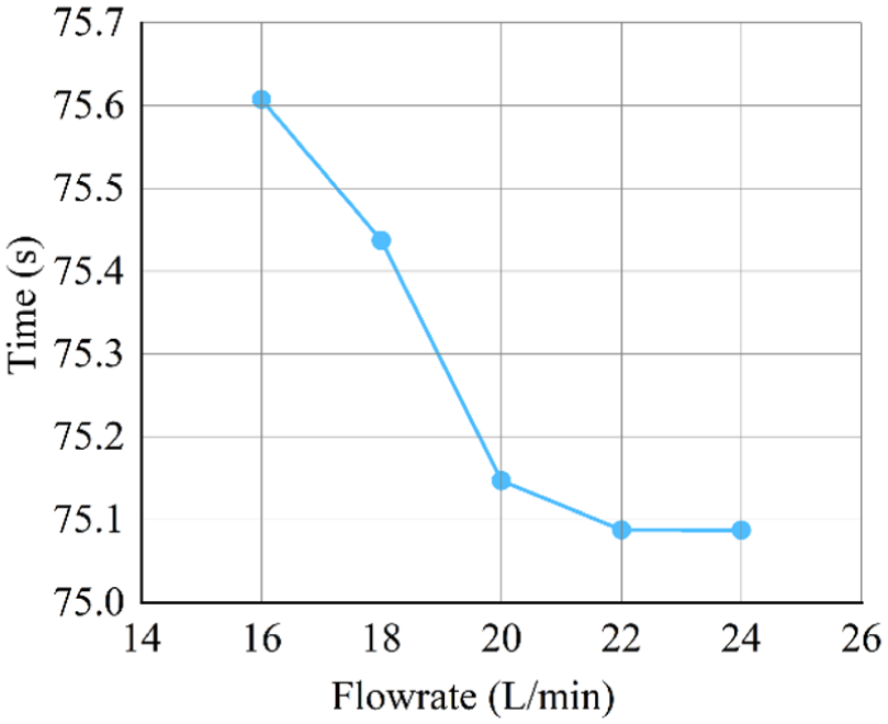
The varied relationship between the characteristic flowrate of the reversing valve of the support cylinder and the motion cycle of the drilling robot.
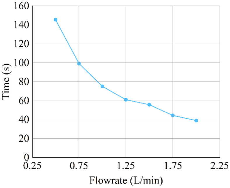
The varied relationship between the characteristic flowrate of the reversing valve of the telescopic cylinder and the motion cycle of the drilling robot.
Figure 17 shows that when the characteristic flowrate of the reversing valve of the telescopic cylinder is kept unchanged and the characteristic flowrate of the reversing valve of the support cylinder is adjusted, the overall motion cycle is slightly reduced. When the characteristic flowrate of the reversing valve of the support cylinder is greater than 22 l/min, the motion cycle of the drilling robot remains unchanged. The phenomenon shows that under the condition of small characteristic flowrate of the reversing valve of the telescopic cylinder, adjusting the characteristic flowrate of the reversing valve of the support cylinder has little effect on the motion cycle of the drilling robot. Figure 18 shows that when the characteristic flowrate of the reversing valve of the support cylinder is kept unchanged, the motion cycle of the drilling robot decreases obviously with the increase of the characteristic flowrate of the reversing valve of the telescopic cylinder. The motion cycle of the drilling robot is reduced from 145.35 to 39.4 s. Meanwhile, the trend of change gradually decreases.
Next, the values of maximum characteristic flowrate of the reversing valve of the support cylinder and the telescopic cylinder were exchanged. The maximum characteristic flowrate of the reversing valve of the support cylinder was modified to 1 l/min. The maximum characteristic flowrate of the reversing valve of the telescopic cylinder was modified to 20 l/min. According to the same change, the same law of motion cycle of the drilling robot was obtained.
All the above results indicate that the overall motion cycle is more sensitive to the change of characteristic flowrate of the small flow valve. Based on above research, the main factor determining the motion cycle of the drilling robot was confirmed. Without considering the structural change and adding the delay of control, the main factor determining the motion cycle of the drilling robot is the distribution of flowrate in the system. The extreme value of the motion cycle of the drilling robot depends on the minimum flowrate of the driving cylinder of the motion system.
Control response law of WOB and ROP of the drilling robot
Control response law of the drilling robot by using univariate control model
(1) Univariate control model of the drilling robot
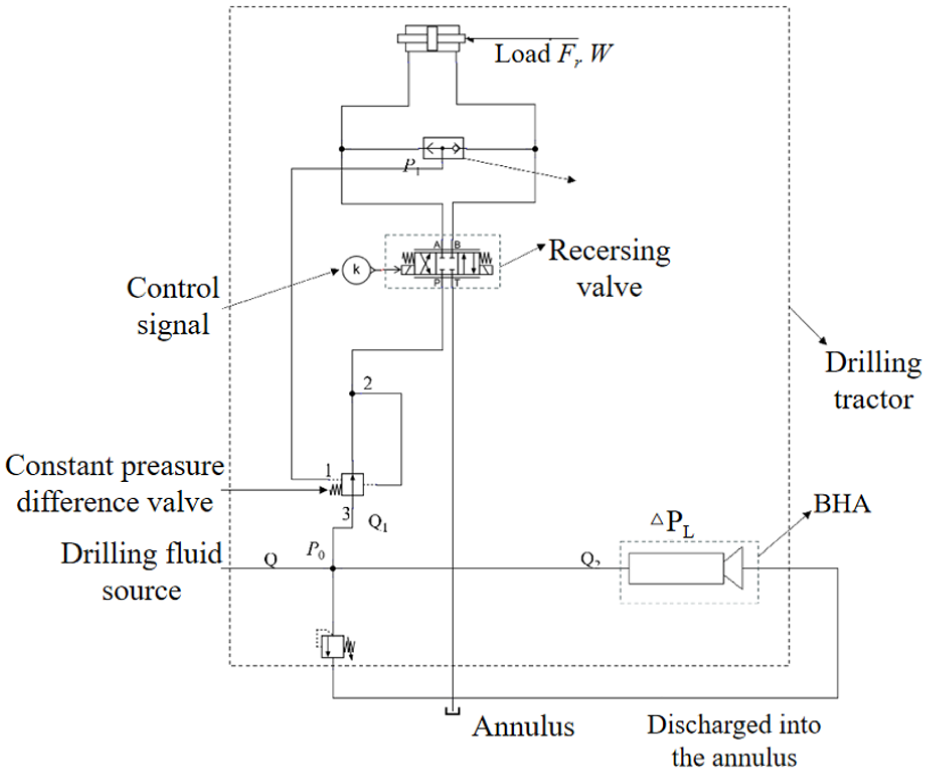
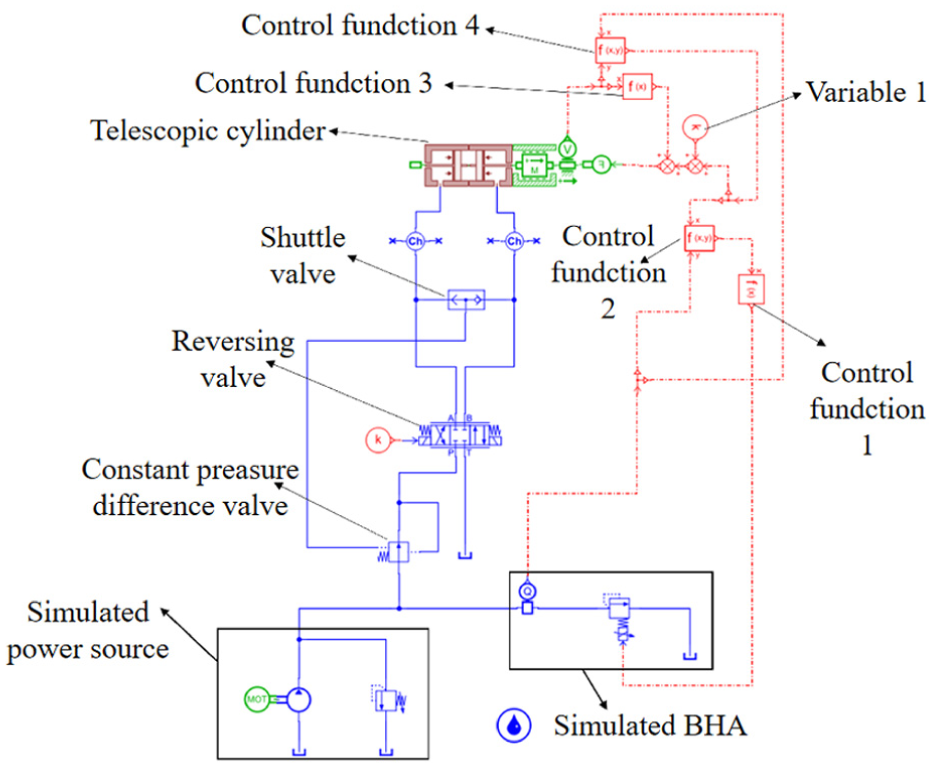
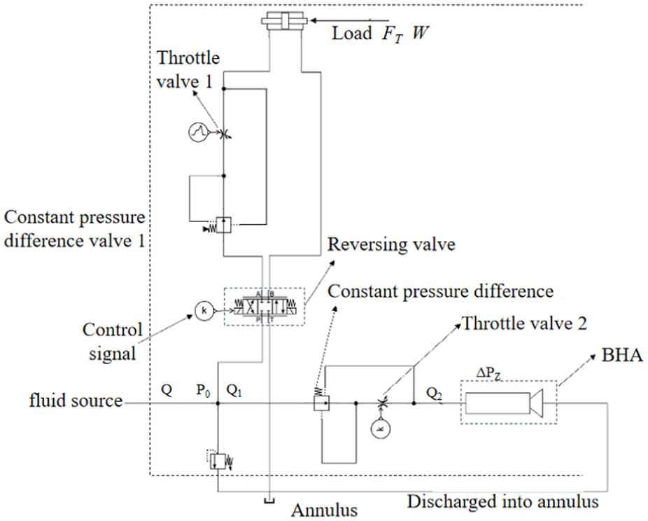
The drilling robot is powered by drilling fluid. And the power of the drilling robot comes from the drilling fluid supplied form ground. Drilling fluid is supplied to the working cylinder group, drilling tool, drill bit through the hydraulic system of the drilling robot. Or part of drilling fluid is discharged directly from the annulus. The stabilities of drilling and crawling of the drilling robot are vital significant. WOB and ROP of the drilling robot are strongly influenced by the fluctuation of pressure and the fluctuation of flowrate in the hydraulic system of the drilling robot. The drastic fluctuation of pressure and the drastic fluctuation of flowrate can lead to the damage of the drilling bit and drilling tool. In order to achieve the relatively stable crawling and drilling of the drilling robot, an univariate control model of WOB and ROP of the drilling robot based on load sensitive circuit was designed.16–19,20 The univariate control model compensates pressure and controls flowrate. The working principle and the relationship between physical quantities are shown in Figure 19.
The diagram of principle of univariate control model of WOB and ROP of the drilling robot based on load sensitive loop.
The drilling tool and screw were usually driven by a telescopic cylinder during the process of drilling. Therefore, the drilling robot was simplified to a telescopic cylinder. As shown in Figure 19, the dotted line represents the components in the drilling robot system. And the solid lines are used to represent the flowrate and paths of liquid in the system. The load on the front end of the telescopic cylinder is the reaction force or telescopic traction force of the front screw and drill bit. After drilling fluid entered the drilling robot, drilling fluid flowed through the paths of liquid to the telescopic cylinder and the front-end BHA ( including drilling tool and drilling bit ) respectively.
When the reaction force of BHA increased, the load of the telescopic cylinder increased. It caused the decrease of the pressure difference between the front and back of the reversing valve. When the port of the reversing valve was unchanged, the flowrate into the cylinder decreased Q1 decreased and Q2 increased). It caused the decrease of the propulsive velocity of the telescopic cylinder and the increase of ROP of the BHA. When the reaction force of BHA decreased, the load of the telescopic cylinder decreased. It caused an increase in the pressure difference between the front and back of the reversing valve. When the port of the reversing valve remained unchanged, the flowrate into the cylinder increased Q1 increased and Q2 decreased). It caused an increase in the propulsive velocity of the telescopic cylinder. As the load changed at any time during the drilling process, this process led to frequent fluctuations in the WOB and ROP of the drilling tool. Therefore, the vibration of BHA was aggravated, and the damage of the drilling tool was caused easily. 21 Similarly, the fluctuation of flowrate and the fluctuation of pressure caused by the source of drilling fluid also led to the above process.
Based on the load sensitive loop, when the fluctuation of pressure and the fluctuation of flowrate caused by the outside were transmitted to the reversing valve, the constant pressure difference valve was offset within the adjustable range. Q1 is connected with three port of the constant pressure differential valve. One port and two port of the constant pressure differential valve are connected before and after of the reversing valve. The pressure difference between the one port and the two port is the pressure difference of the reversing valve. At the same time, the shuttle valve is connected with the left and right cavities of the telescopic cylinder, allowing any end of high pressure to pass. When the pressure at the end of high-pressure increases, the flow area is reduced. And the difference of throttle pressure is increased to reduce the pressure at the end of high pressure. Similarly, the pressure at the end of high pressure is maintained when the pressure at the end of high-pressure decreases.
The control loop has the advantages of high sensitivity and adjustable control range. Through the above control system, the pressure difference between the front and back of the reversing valve is kept constant. The flowrate through the reversing valve is guaranteed (the flowrate of inlet of the telescopic cylinder is stable). And the flowrate of Q1 and Q2 is guaranteed. The loop can adjust the pressure by adjusting the constant pressure difference valve to adjust the flowrate of the telescopic cylinder and control WOB and ROP.
(2) Simulation of univariate control model of the drilling robot
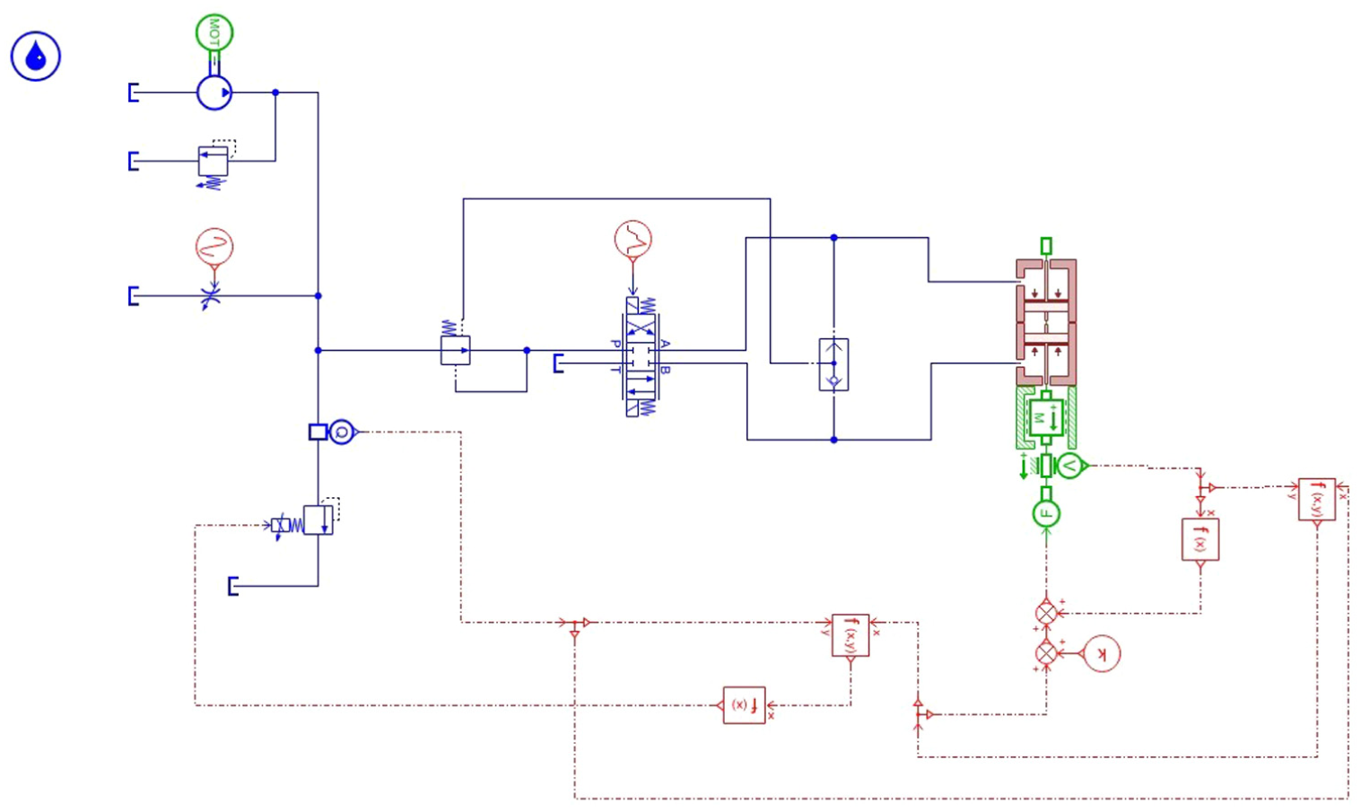
According to the previous analysis, the drilling robot was propelled by the telescopic cylinder in the process of moving and drilling. Therefore, the overall model of drilling robot was simplified to a driving model of single telescopic cylinder. The univariate control model of drilling robot is shown in Figure 20.
The univariate control model of drilling robot.
In the univariate control model, the consumable flowrate of BHA was simulated by the flow sensor and the electromagnetic relief valve. The velocity parameter of motion cylinder was output by the velocity sensors connected to the mass of the telescopic cylinder. The velocity parameter and flowrate parameter were combined to deduce WOB and ROP of the system. The functions of WOB and ROP are shown in function (1) to function (4). 22

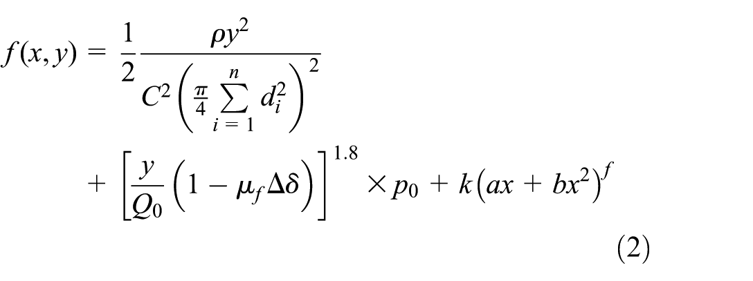
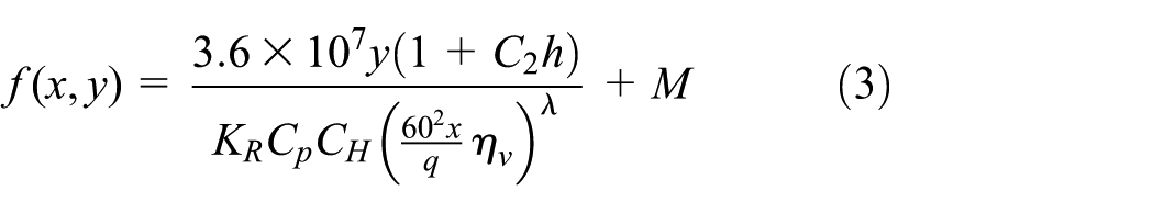

In the function (1),
According to the principle of control of the univariate control model, the fluctuation of pressure and the fluctuation of flowrate were curbed by controlling the setting pressure and range of the constant differential pressure valve. By controlling the setting pressure and range of the constant differential pressure valve, the flowrate through the reversing valve (the flowrate into the telescopic cylinder) was stabilized. Meanwhile, WOB and ROP were indirectly controlled by controlling the setting pressure and range of the constant differential pressure valve.
The flowrate of drilling fluid and the version of fixed valve were given. The setting pressure of the constant differential pressure valve was adjusted to set the pressure from 10 to 20 bar. And the time of simulation was set to 10 s. The parameters such as the flowrate of inlet of the telescopic cylinder, WOB, ROP, and the flowrate of the drilling tool were output. The changes of above parameters are shown in Figures 21 to 24. It can be seen from Figures 21 to 24:
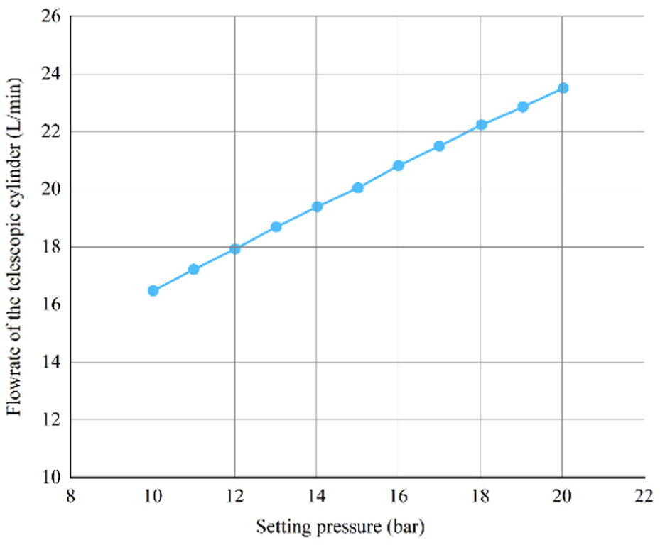
The curve of the flowrate of the telescopic cylinder changing with the setting pressure of the constant pressure differential valve.
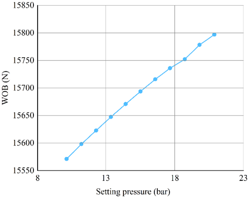
The curve of WOB changing with the setting pressure of the constant pressure differential valve.
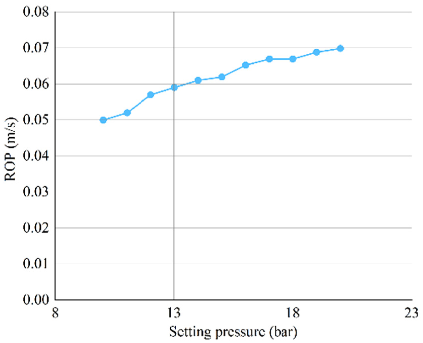
The curve of ROP changing with the setting pressure of the constant pressure.
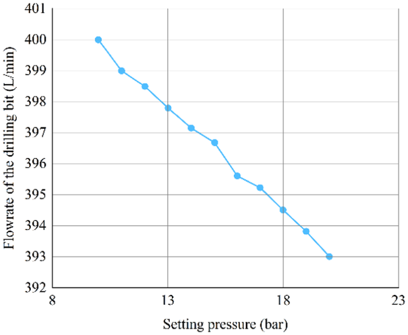
The curve of the flowrate of the drilling bit changing with the setting pressure of the constant pressure differential valve.
Quantitative analysis of Figure 21 shows that the flowrate changes linearly, yielding a control sensitivity of approximately 0.7 l/min per bar with the setting pressure of the constant pressure difference valve. The above phenomenon’s show that the pressures at both ends of the reversing valve are stabilized by controlling the constant pressure difference valve of the loop. Linearly adjusting the flowrate of inlet of the telescopic cylinder is of great value for achieving stable drilling and shrinkage.
Figures 22 to 24 show that WOB and ROP change with the setting pressure of the constant differential pressure valve, and they are close to linearity. However, the change is small. This is mainly because the reversing valve has weak throttling capacity and small pressure drop. Meanwhile, the constant pressure difference valve has limited adjustment ability.
The setting pressure of the constant pressure difference valve was kept constant at 10 bar. The inhibitory effect of the load sensitive loop on the fluctuation of pressure and fluctuation of flowrate was analyzed. The variable throttle valve was added to the trunk of inlet. And the valve opening of the throttle valve was frequently changed. The fluctuation of pressure and fluctuation of flowrate of drilling fluid during the drilling process were simulated by artificial fluctuation of pressure and fluctuation of flowrate. The sine wave signal was input to change the pressure and flowrate of input drilling fluid. The control model after the change is shown in Figure 25. The effect of stabilization when flowrate fluctuates is shown in Figure 26. It can be seen form Figure 26: 23
The model of fluctuation of load.
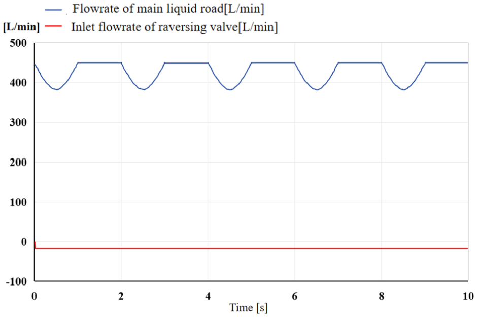
The effect of pressure stabilization when flowrate fluctuates.
Figure 26 shows that under the action of the throttle valve, the flowrate of the main liquid loop has a significant fluctuation. The flowrate of inlet of the reversing valve has no significant fluctuation in the loop under the action of the load sensitive loop. The load-sensitive loop successfully suppressed the 60 l/min amplitude oscillation to near-zero, achieving a fluctuation attenuation rate exceeding 95% of pressure and flowrate. Therefore, hydraulic components can be effectively protected in practical use. And the life of the drilling robot can be improved.
Therefore, the above method of adjustment has obvious effect on stabilizing the motion velocity of the telescopic cylinder and offsetting the fluctuation of pressure and fluctuation of flowrate. However, the ability of adjustment of WOB and ROP of the drilling robot is slightly insufficient. Therefore, the components with stronger throttling ability are added to increase the range of adjustment of load sensitive loop. Meanwhile, the control loop for BHA loop is set to achieve batter effect on controlling WOB and ROP, and stabilizing the pressure and flowrate.
Control response law of the drilling robot by using multivariable control model
(1) Multivariable control model of the drilling robot
In the development of the multi-variable control model, the drilling robot system was simplified into a lumped-parameter model driven by a single telescopic cylinder. This decoupling strategy was deliberately chosen to focus on the core principle of the load-sensing control mechanism and its continuous regulatory characteristics on weight on bit (WOB) and rate of penetration (ROP). While actual drilling involves the coordinated cross-motion of front and rear mechanisms (a discrete sequential logic), the transient fluid dynamics dictating WOB and ROP are dominantly governed by the single active pushing cylinder. Therefore, simplifying the system allows for the isolation of hydraulic responses without discrete switching noise. Future research will integrate the cooperative logic of multiple hydraulic cylinders to reflect the overall motion characteristics. Based on the above simplifications, this section presents the multi-variable control model as illustrated in Figure 27.
The diagram of principle of multivariable control model of WOB and ROP of the drilling robot based on load sensitive loop.
The load sensitive control loop was proposed in the previous section to solve the problem of the large fluctuation of pressure and the large fluctuation of flowrate caused by the load of the drilling robot and external factors. The above control system considered the flowrate of the drilling fluid entering the telescopic cylinder. By controlling the flowrate of the drilling fluid entering the telescopic cylinder, the flowrate of BHA was indirectly controlled and suppressed. The above control system is more suitable under the conditions of small fluctuation of WOB and no start of drilling tool in the traction process. Univariate control model is not accurate enough to control WOB and ROP, and the setting pressure of the system is not considered. Therefore, a multivariable control model of WOB and ROP was proposed, as shown in Figure 27. It can be seen from Figure 27 that:
The constant pressure difference valve and the controllable throttle valve were used to compose a control loop of load-sensitive velocity. The control loop of load-sensitive velocity inhibited the fluctuation of flowrate and pressure of drilling fluid entering the drilling tool and controlled the flowrate and pressure entering the drilling tool. Meanwhile, the control loop of the drilling robot was improved and the controllable throttle valve was added. The control loop composed of the controllable throttle valve and the constant pressure difference valve to improve the control ability and control range. The above loop and the main relief valve together constituted the multivariable control model of WOB and ROP of the drilling robot. The controllable variables in this scheme include the setting pressure of system, the setting pressure of the constant pressure difference valve of the telescopic cylinder, the throttle valve opening of telescopic cylinder, the setting pressure of the constant pressure difference valve of the drilling tool and the throttle valve opening of the drilling tool. Through above variables, the flowrate distribution in the drilling robot system can be effectively controlled. And the fine control of WOB and ROP of the drilling robot can be achieved.
(2) Simulation of multivariable control model of the drilling robot
Based on the previous analysis, a multivariable control model was designed. The diagram of new model of control loop is shown in Figure 28. The principle is similar to the univariate control model. Ignoring the throttling pressure difference of the reversing valve, the range of adjustment is increased by the controllable throttle valve. The combination of controllable throttle valves and constant pressure difference valves can achieve good linear control effect. Meanwhile, the loop of the telescopic cylinder and the loop of the drilling tool are controlled by their corresponding control methods to achieve separate or coordinated control. The methods make the control means more diverse and accurate, and have better working condition adaptability.
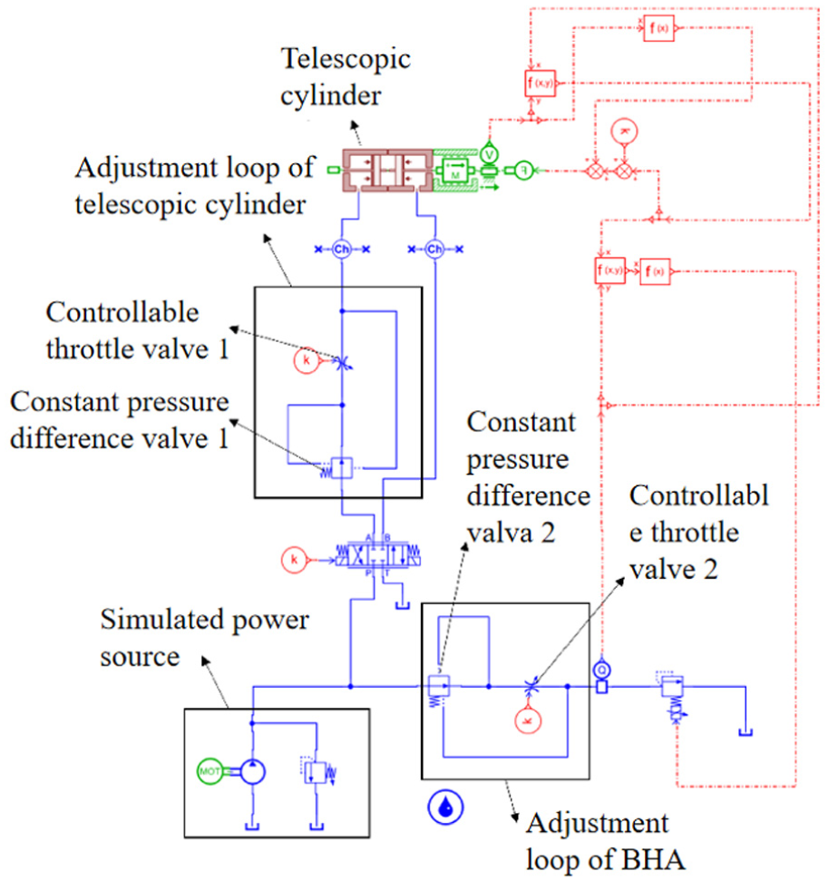
The multivariable control model of drilling robot.
The flowrate of the drilling fluid was kept constant at 7.5 l/min. The setting pressure of the relief valve of the drilling robot was set 150 bar. The opening diameter of throttle valve was 5 mm. The opening of controllable throttle valve 2 was set 0.5. The setting pressure of the constant pressure difference valve 1 was set 10 bar. The setting pressure of the constant pressure difference valve 2 was set 400 bar. The opening of constant pressure difference valve 1 was adjusted from 0 to fully open. The distribution of WOB, ROP and flowrate is shown in Figure 29. It can be seen from Figure 29:
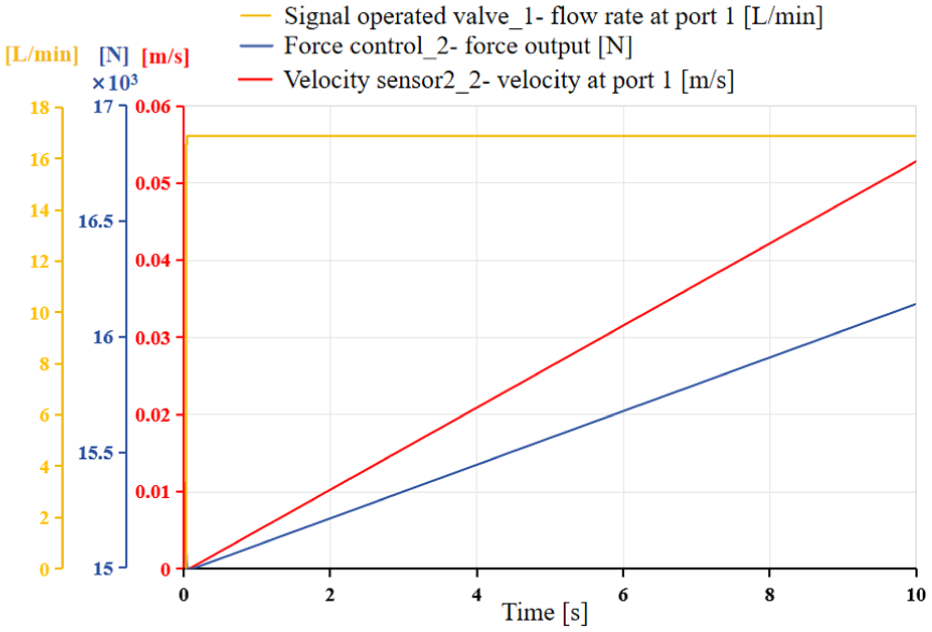
The curve of WOB and ROP rate with throttle valve 1 opening.
Figure 29 shows that WOB and ROP maintain an excellent linear change with the throttle valve opening within the range of adjustment. The above result indicates the control loop has an excellent effect of adjustment. The WOB and ROP are adjusted with linear and infinite law in a certain range. Meanwhile, the flowrate of the drilling bit is stabilized to provide a guarantee for efficient drilling and rock breaking.
Discussion: Comparison with advanced control algorithms
It is worth noting that in recent years, advanced intelligent control algorithms, such as filtered disturbance rejection control and multilayer neuroadaptive reinforcement learning via actor-critic mechanisms, have been widely utilized to solve complex nonlinear control problems. 25 These state-of-the-art methods offer superior dynamic precision and self-learning adaptability. Compared with the above algorithms, the purely hydraulic load-sensitive control strategy proposed in this study has distinct advantages and disadvantages. The primary disadvantage is that mechanical-hydraulic feedback exhibits slightly lower absolute control precision and a slower dynamic response compared to high-frequency computational algorithms. However, the downhole drilling environment presents extreme challenges, including severe vibrations, high pressures, and extreme temperatures (>150°C), which severely restrict the deployment of delicate high-bandwidth electronic sensors and high-performance computing units required for neuroadaptive reinforcement learning. In this context, the proposed load-sensitive models demonstrate overwhelming practical advantages. By utilizing constant pressure difference valves and throttle valves to form a purely physical feedback loop, the system successfully regulates WOB and ROP without relying on fragile downhole electronics. This guarantees exceptional systemic robustness, physical reliability, and environmental adaptability, making it a highly feasible solution for actual downhole engineering.
Conclusions and prospects
Conclusion
(1) A novel drilling robot based on hydraulic system was designed and modeled, which included upper joint, rear traction mechanism, control section, front traction structure and lower joint. The model of motion of the drilling robot with load was established, which added the judgment logic of the support cylinder and telescopic cylinder and added simulated BHA. Analyzed the influencing factors on the motion characteristics of the drilling robot comprehensively. Research results showed that the extreme value of the motion cycle of the drilling robot depends on the minimum flowrate of the driving cylinder of the motion system. The main factor determining the motion characteristics of the drilling robot is the distribution of flowrate in the system.
(2) After researching the motion characteristics of the drilling robot, the univariate control model and multivariable control model based on the load sensitive principle were proposed innovatively. The univariate control model and multivariable control model used the constant pressure difference valve and the controllable throttle valve to control WOB and ROP of the drilling robot. Analyzed the control response law of the univariate control model and multivariable control model of the drilling robot. 26 Research results showed that the flowrate of inlet of the telescopic cylinder change approximately linearly with the setting pressure of the constant pressure difference valve in the univariate control model. And WOB and ROP change with the setting pressure of the constant differential pressure valve, and they are close to linearity. WOB and ROP maintain an excellent linear change with the throttle valve opening within the adjustment range in the multivariable control model. The multivariable control model have more precise ability of controlling WOB and ROP.
Based on the above results, the proposed univariate control model and multivariable control model have excellent ability to suppress the fluctuation of WOB and ROP. The proposed univariate control model and multivariable control model of the drilling robot have great significance to realize stable drilling process and provide reference and basis for the development of controlled algorithm of the drilling robot.
Prospects and future work
Due to the complexity of reproducing downhole geological interactions in a laboratory setting, the closed-loop control performance of WOB and ROP has not yet been verified by field data. The simulation results in this paper serve as a critical theoretical basis and parameter guidance for the next phase of research.
Future work will focus on: Building a specialized bench test rig to simulate wellbore friction and formation resistance. Conducting physical experiments on the prototype to calibrate the flowrate coefficients and validate the control response laws proposed in this study. Ultimately, field trials will be performed to assess the robot’s adaptability to complex downhole environments.
Footnotes
Appendix
Handling Editor: Aarthy Esakkiappan
Funding
The authors disclosed receipt of the following financial support for the research, authorship, and/or publication of this article: This work was funded by the Natural Science Foundation of China (52374006), National Science and Technology Major Project Project (2025ZD1407003), and Sichuan Science and Technology Program (2024YFHZ0155). The authors also sincerely thank the editors and the reviewers for their efforts in improving this paper. The authors also sincerely thank the editors and the reviewers for their efforts in improving this paper.
Declaration of conflicting interests
The authors declared no potential conflicts of interest with respect to the research, authorship, and/or publication of this article.