
Abstract
With its flexibility in operation, rapid inspection capability, omnidirectional detection, and strong terrain adaptability, the quadrotor has become an effective tool for underground inspection. The underground environment is characterized by narrow passages and turbulent airflow. When encountering strong gusts in underground spaces, the quadrotor maintains a large attitude angle to ensure stability. There is an significant model deviation between the actual dynamic model of the quadrotor and the hovering dynamic model. In general, the controller of the quadrotor is designed based on the hovering dynamic model in still air. The deviation between the model in the controller and the actual model can lead to the loss of control of the quadrotor. To overcome the problem above, at the environmental perception level, a real-time wind field prediction model is constructed based on the information obtained by wind speed sensors. By integrating this predicted information with an improved adaptive extended set membership filtering algorithm, a multi-step incremental prediction mechanism is introduced. At the control architecture level, a dynamic model compensation mechanism is proposed for nonlinear system characteristics. By identifying model bias online, an active model correction strategy is established. The incremental predictive control value is used as the feedforward compensation input, and an optimal control problem with constraints is established. Finally, a simulation example is presented to verify the effectiveness of the quadrotor control method.
Introduction
The working environment in coal mines is extremely harsh, 1 and there are great risks for inspection personnel using traditional manual inspection methods. The use of robots for inspections is becoming a mainstream trend in underground environments. At present, coal miners need to carry professional equipment to conduct inspections in underground tunnels every day, in order to identify potential hazards promptly. This labor-intensive job exposes workers to constant high risks.
The inspection of coal mine tunnels mainly relies on ground robots, which include tracked and wheeled configurations. However, ground robots have limited mobility on complex terrains, and often have blind spots in the field of view. It is difficult for these configurations to meet requirements in complex and diverse environments. With the rapid development of unmanned aerial vehicle(UAV) technology, applications of quadrotors have become a research focus. Quadrotors are widely used in industrial inspection, aerial photography, agricultural operations and other fields.2,3 Benefiting from flexible operation, rapid inspection, omnidirectional detection, and strong terrain adaptability, quadrotors enable inspections in complex underground environments. Thus, quadrotors are poised to become a significant robot configuration for underground inspections.
The quadrotor is classified as an underactuated system since it possesses only four control inputs yet generates six motion outputs. Input signals consist of the desired rotation rates of the four motors, while the outputs encompass three translational coordinates and three rotational coordinates relative to the quadrotor’s body axes. The quadrotor also exhibits nonlinear coupling dynamics. Three factors contribute to this. First, attitude representation is nonlinear. It evolves on SO(3)—the mathematical group of all three-dimensional rotations—which means Euler angles suffer from trigonometric singularities. Second, translation and attitude are coupled: thrust must be rotated from the body frame to the inertial frame using a rotation matrix, and horizontal motion requires tilting the vehicle to direct thrust. Third, gyroscopic effects arise from the cross product of angular velocity and angular momentum, introducing quadratic nonlinearities. Finally, the quadratic mapping from rotor speeds to thrust and moments compounds these effects.
For quadrotors, existing control methods can mainly be divided into three categories: linear control, nonlinear control, and intelligent control methods. Li and Li 4 designed a Proportional-Integral-Derivative (PID) controller for three-dimensional position and attitude control of quadrotors. Simulation results show that the quadrotor can stably fly under wind disturbance, but with slight overshoot. Pan et al. 5 similarly developed an optimal PID controller with a Kalman filter for target trajectory estimation. Their results indicate that the system can quickly reach the desired height without steady-state error, yet exhibits significant overshoot.
To overcome the above overshoot problem, Okyere et al. 6 propose a step-by-step LQR controller to control the altitude motion of quadrotors. Their numerical experiments show that if the R value is high and the K value is low, the response speed will be slower. When the K value is high, the state response reaches zero faster, but the controller response has large steady-state error. Shah et al. 7 study the trajectory tracking control of quadrotors using gain scheduling integral LQR, where an integral term is added to improve the tracking performance of the quadrotor. Their results indicate that the continuous gain control law can solve the problems of jitter and discontinuity.
In order to control the attitude response of the quadrotor, Han et al. 8 develop an H∞ controller based on the gray-box method, and conduct related experiments. 9 Rich et al. 10 study a robust H∞controller for quasi-hover conditions using the Glover-McFarlane loop shaping method. Bonna and Camino11–13 study linearization of the feedback for achieving attitude control and stabilizing the quadrotor. Lu et al. 14 propose a backstepping controller, which uses online optimization techniques to control the position and attitude of quadrotors. Their strategy can simultaneously solve path planning and tracking control problems, as traditional control designs only address these problems separately. First, accessible trajectories are generated by the planning generator, and then the tracking controller is adjusted and optimized to achieve the new planned path. The experiment shows that the accuracy of the quadrotor trajectory is within an acceptable range. Dydek et al. 15 investigate an adaptive controller for the quadrotor with the baseline trajectory tracking controller to enhance system performance. The effectiveness of this approach is validated through both simulations and indoor experiments. Their adaptive controller demonstrates strong robustness against parameter uncertainties. The controller is particularly effective in mitigating the impact of abnormal loss of thrust caused by component failures or physical damage.
Shao et al. 16 investigate a collision-free elliptical target encirclement cooperative control method with improved convergence characteristics for UAVs under wind disturbances. First, an enhanced fixed-time encirclement guidance law is designed, enabling UAVs to reach user-preset elliptical trajectories within explicit time constraints independent of initial state conditions. This guidance law achieves rapid error decay through a carefully designed radial error feedback mechanism (with power terms dynamically switching between fractional exponents and polynomial terms). Specifically, they 17 employ a simple filtering-based unknown system dynamics estimator to precisely compensate for uncertainties such as wind disturbances in a computationally efficient manner.
Cömert et al. 18 and Castillo Zamora et al. 19 study the sliding mode controller (SMC) for the position and altitude control of quadrotors. The results indicate that the settling time of the SMC controller is shorter, but it can generate large pitch and roll angles exceeding 20°, which is unfavorable in practice. As an alternative approach, the model predictive controller (MPC) is used to control processes while satisfying a series of constraints. This controller relies on a linearized dynamic model obtained through the system identification process. Ganga and Dharmana 20 conduct a comparative study between traditional PID controllers and MPC for the altitude motion control of the quadrotor. Simulation results show that compared with PID, MPC has better control characteristics, which has shorter settling time and no overshoot.
Intelligent controllers are mainly designed based on bionic principles, such as fuzzy theory or neural network theory. Raza and Gueaieb 21 propose a fuzzy logic controller to control the position and attitude angle of the quadrotor under disturbance conditions. The results show that the fuzzy logic controller can provide good performance even under sensor noise and wind disturbance. Zare et al. 22 study the trajectory tracking control of the quadrotor using a fuzzy logic controller. The simulation results show that the fuzzy logic controller performs well in tracking the desired position and attitude angle of the quadrotor.
The sizes of mine tunnels are only 2–5 m in width and 3–6 m in height. Due to narrow spaces, abrupt airflow changes in turning areas, and ground effect interference, the quadrotor inspection in underground environment still remains a challenge. For instance, in tunnels, drones must maintain a minimum safe distance of 0.5 m from coal walls to prevent collisions and stay at least 0.5 m above the ground to mitigate ground effect disturbances. There is no natural wind in complex underground environment, and fans are used for air exchange usually. The fans usually have a high power and produce a large local airflow. The underground mining area has a complex network containing various T-shaped intersections and crossroads. Due to the narrowness of the channels, strong wind disturbances consisting of steady winds and gusts readily form. Given the quadrotor’s underactuated nature, multivariable coupling, and nonlinear dynamic characteristics, its control stability may significantly decrease under strong external disturbances during underground inspection.
The existing control schemes (such as traditional PID algorithm and sliding mode control algorithm) have obvious shortcomings in dealing with sudden underground disturbances. On the one hand, insufficient state prediction accuracy leads to control command oscillations and trajectory deviations; On the other hand, the quadrotor maintains a large attitude angle to ensure stability when encountering strong gusts in underground spaces. There is a significant model deviation between the actual dynamic model of the quadrotor and the hovering dynamic model. The controller of the quadrotor is usually designed based on the hovering dynamic model in still air. The deviation between the model in the controller and the actual model can lead to loss of control. In particular, the trajectory deviation caused by wind disturbances becomes the main threat to quadrotor flight safety.
To overcome the problem above, this study proposes corresponding improvement methods. At the environmental perception level, a real-time wind field prediction model is constructed through wind speed sensor data and proper orthogonal decomposition (POD) method.23–25 Combined with an improved adaptive extended set membership filtering (ASMF) algorithm, a multi-step incremental prediction mechanism is introduced. This mechanism effectively compensates for model bias caused by flight mode switching and operating point migration by predicting the optimal control effect over multiple future control cycles, while an online update strategy is adopted to reduce computational complexity. At the control architecture level, considering online identification of model bias, an active model correction strategy is established, and an optimal control problem with constraints is constructed. By solving the above optimal control problem for the compensation amount in real-time, effective control of the quadrotor in underground environments is achieved.
To address challenges posed by complex underground environments to quadrotor inspection, this study proposes a series of methods. The contributions are summarized as follows. (1) Conventional control approaches typically rely on fixed mathematical models, rendering them prone to failure when dynamic models severely mismatch actual quadrotor states due to turbulent airflow and confined spaces in underground environments. In contrast, the proposed method dynamically identifies model deviations by real-time monitoring of discrepancies between system states and predicted values, subsequently adjusting control parameters online for rapid adaptation. This eliminates dependence on offline recalibration, significantly enhancing control robustness. (2) Traditional methods lack active compensation mechanisms for disturbance rejection. Upon encountering sudden disturbances such as strong airflow, they experience feedback delays and rely on fixed parameters, making timely attitude adjustment impossible. The proposed method employs multi-step incremental prediction results as feedforward signals to preemptively compensate for future disturbance effects, overcoming inherent latency limitations of conventional feedback control. Such an approach substantially improves dynamic response and reduces control deviations. As quadrotors are strongly coupled nonlinear systems, traditional linear methods struggle to handle complex coupling between attitude and position, particularly under model mismatch. In this study, a constrained optimal control problem is formulated that comprehensively considers actuator limits and safety boundaries, ensuring effective and safe control. This avoids control commands exceeding actuator limits due to neglected constraints in conventional methods. (3) Furthermore, whereas traditional prediction methods exhibit weak environmental perception, inability to perceive dynamic changes in real-time, and low multi-step prediction accuracy with error accumulation, we propose a method to compute compensation values efficiently in real-time. This guarantees that the nominal controller maintains high-performance control under model mismatch conditions, sustaining its precise control throughout operation. Consequently, it satisfies stringent demands of underground inspection for long-term trajectory planning and precise control, thereby enabling precise inspection in complex underground environments.
The remainder of this paper is organized as follows. In Section 2, a real-time wind field prediction model is constructed through wind sensor information and the POD method. In Section 3, the dynamic modeling of the quadrotor is introduced. In Section 4, an optimal control state prediction algorithm is proposed, integrating predicted wind data with a multi-step incremental prediction mechanism. In Section 5, an active model correction strategy is introduced to adaptively refine the dynamic model based on real-time deviations, followed by the formulation of the optimal control problem. In Section 6, numerical simulations are given to validate the effectiveness and robustness of the proposed methods. Finally, the conclusions of this study are presented in Section 7.
Dynamic modeling of the quadrotor
We begin by defining the coordinate frames. The local inertial frame
When the axes

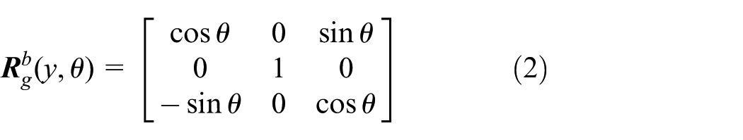

The transformation matrix from the local inertial frame to the body frame for three -axis rotation can be expressed as

The above matrix represents the relationship that quadrotor first rotates

During the flight, the quadrotor is mainly subjected to the following forces and moments: gravity, lifts generated by rotor rotation, moments caused by these lifts, the torques generated by rotor rotation, and additional force brought by the air. As shown in Figure 1, the wheelbase between adjacent rotors is
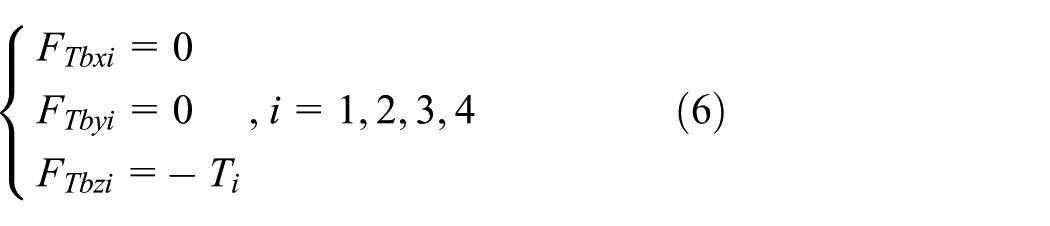
Where

where


Force analysis of quadrotor.
The counter torque of each rotor can be determined by the following equation

where

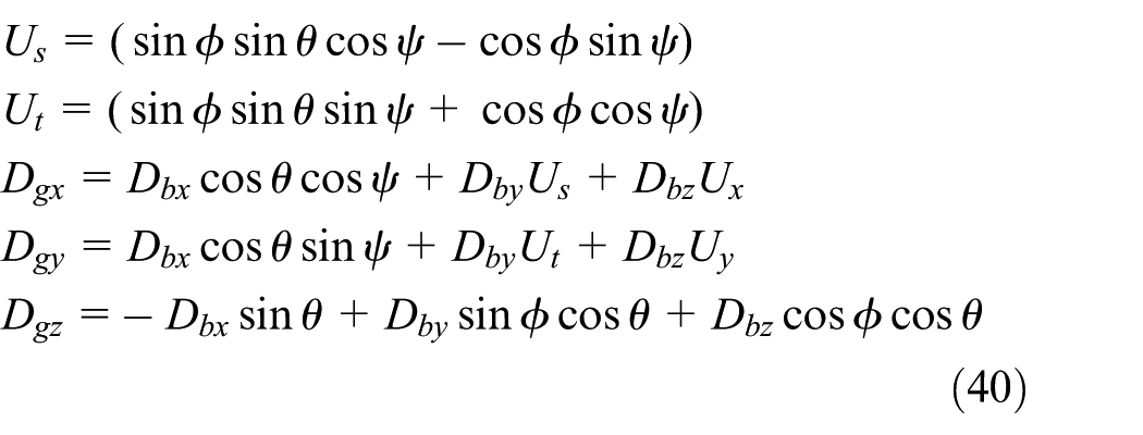
The three-axis components of the body’s gravity in the body frame can be transformed through coordinate transformation relationships as follows
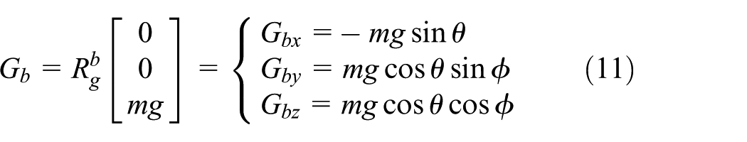
Thus,

where

In the above equation,
The overall external force vector, the velocity vector and angular velocity vector of the body frame are defined by

The derivative
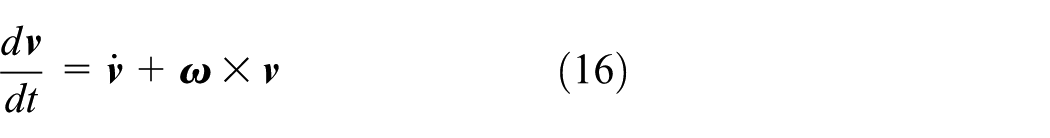
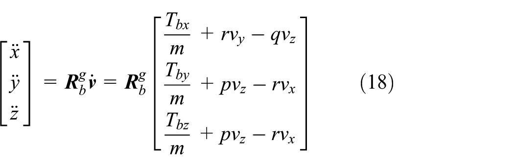
Substituting equation (16) into equation (15) yields

where
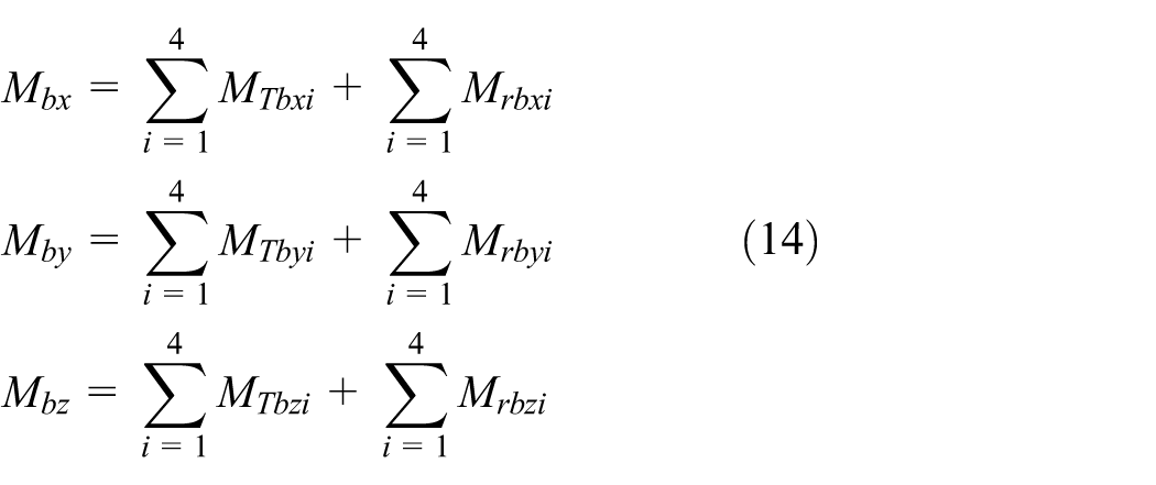
According to the law of angular momentum, it can be concluded that

where

By substituting equation (20) into equation (19), we can obtain

Expanding the above equation yields the rotational dynamics in component form:

The relationship between the angular velocity of the body and the Euler angular velocity can be expressed as:

where
we have

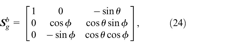
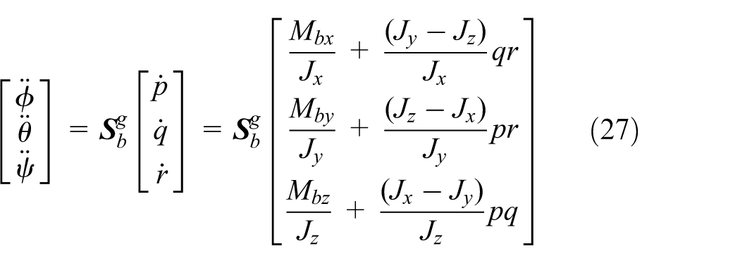
The angular velocity conversion matrix from the body frame to the local inertial frame is as follows:

Combining equation (22) and equation (25), the dynamic equation in the local inertial frame may be given by
Gust load prediction based on observation data and POD method
The underground environment is complex and time-changing, and it is easy to generate random local gusts of wind. In underground mines, gusts of wind are usually caused by the acceleration of airflow in some complex tunnel terrains. The biggest uncertainty of the quadrotor in underground inspections is the loss of control caused by gusts. Therefore, the real-time capability, robustness, and accuracy of gusts prediction are extremely high.
To meet these requirements, we introduce a gust loads prediction method based on the POD method.23–25 First, wind sensors at different locations in underground tunnels and on quadrotors are installed to collect information on environmental wind, and then the intensity and direction of gusts based on the collected data are predicted.
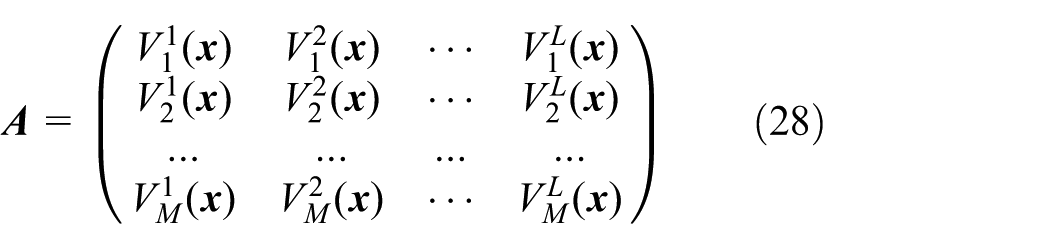
where M denotes the number of grid nodes, and L represents the number of snapshots.
The mean value of these instantaneous images

Using the difference between each sample and the average value of the sample, we obtain a new set of instantaneous images as follows

Let

where

where,

Since the eigenvalues of the matrix

After the POD method is used to obtain the orthogonal basis, it is necessary to select sufficiently large truncation order of basis vectors for approximating

where

By substituting equation (36) into equation (13), the impact of external wind on the quadrotor can be estimated through the POD method. In order to weaken the coupling relationship between the force and torque controlled by each motor, it is assumed that:
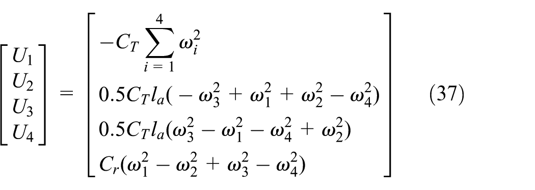
Thus, the control equation for the quadrotor can be written as

where

in which
where
The three-axis position control of quadrotors relies on a single control input

Control diagram of the quadrotor.
where
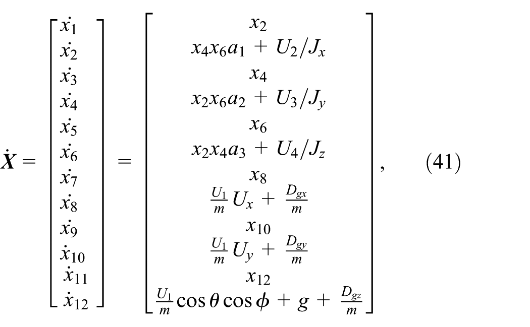
The state equation of the quadrotor can be expressed as follows:

in which,

Thus, the prediction method is as follows. Firstly, open-loop prediction is performed based on the following equation

where

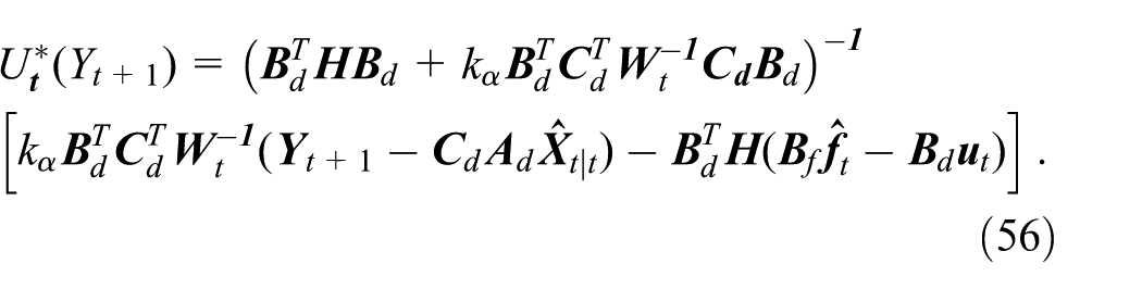
The optimal control input solution above is

where
Predictive control method based on active model
The flight modes of the quadrotors can be divided into the hovering mode (speed below 1 m/s), the cruising mode (speed between 1 and 15 m/s), and the ground approach mode (takeoff and landing or flying close to the ground). In addition, the transitions between modes are not clearly bounded and involve complex transient processes. The dynamic characteristics of the aircraft in hovering mode are relatively stable. In this mode, the effect of the slight changes on the dynamic model is not significant. Because model identification and verification are effective in this mode, the hovering dynamic model is usually selected for the control of the quadrotor. When the quadrotor flies at high speeds or near the ground, the dynamic models of the quadrotor may have significant differences from those in hovering mode.
To describe model uncertainty, we consider linearization errors, internal and external disturbances, and unmodeled dynamics as additive process noise. This noise term not only depends on the system state vector and external disturbances, but also has a coupling effect with the inherent noise characteristics of the system, which needs to be compensated in the controller design. A nonlinear function

in which

The nominal system matrix

The above equation can be rewritten as the following discretization form

This study designs a controller based on the active model (as shown in Figure 3), which obtains compensation
in which

where

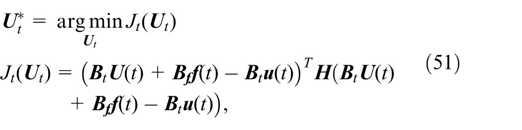
Then we have an optimization problem as follows

By taking into account the index of equation system correction (51) and the stability index of system prediction (52), the following weighted optimization index may be given by

where
where

Set

Assuming that

By substituting equation (62) into equation (48), we have

where

in which

Choose


The control process based on active modelling.
Then

Choose

where

Then we have
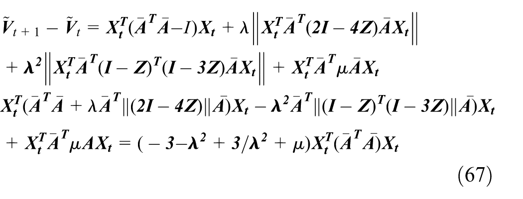
If

This proves that the system is asymptotically stable.
Numerical examples and discussion
Based on field-collected gust data, the POD method is employed for gust prediction. The prediction accuracy is evaluated by comparing the predicted results with actual measurements, as illustrated in Figures 4 to 7. The results demonstrate that the proposed approach achieves accurate gust prediction, validating the effectiveness of the POD-based methodology.

Comparison of wind field data and prediction data along X axis of roadway.

Comparison of wind field data and prediction data along Y axis of roadway.

Comparison of wind field data and prediction data along Z axis of roadway.

Comparison of wind field data and prediction data of total velocity along roadway.
The above gust data were adopted as inputs to simulate hover control performance. Figures 8 to 10 demonstrate that the proposed active model control method effectively attenuates gust disturbances. Quantitative comparison reveals position deviations of merely 0.1 m in both X and Y directions for the proposed method—substantially lower than PID (0.35 m) and adaptive control (0.17 m). In the Z direction, the proposed method maintains altitude without significant descent, whereas PID control may cause altitude loss, posing significant safety risks.
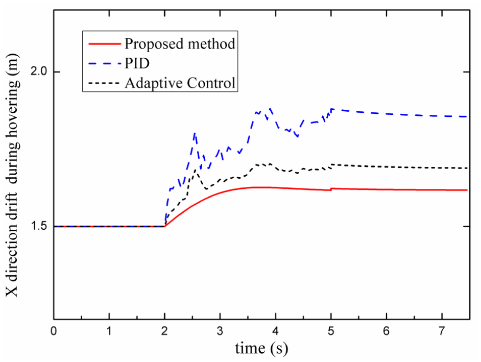
X-axis drift under the control of different controllers affected by gust during hovering.

Y-axis drift of different controllers affected by gust during hovering.

Z-axis drift of different controllers affected by gust during hovering.
The above gust data were employed as inputs to simulate hover control performance. Figures 11 to 13 demonstrate that the proposed active model control method effectively attenuates gust-induced disturbances. Quantitative comparison reveals position deviations of merely 0.1 m in X and Y directions—substantially lower than PID (0.35 m) and adaptive control (0.17 m). In the Z direction, the proposed method maintains altitude without significant descent, whereas PID control may cause altitude loss, posing significant safety risks.

X-axis drift of constant speed flight by different controllers affected by gust.

Y-axis drift of constant speed flight by different controllers affected by gust.

Z-axis drift of constant speed flight by different controllers affected by gust.
Under gust-free conditions, the proposed method, PID and adaptive controllers all achieve accurate elliptical trajectory tracking (Figures 14 and 15). Figures 16 and 17 illustrate the tracking performance under gust disturbances. The proposed method maintains precise path following with minimal deviation, whereas the conventional PID controller exhibits significant trajectory fluctuations. The adaptive control method demonstrates intermediate performance.

The flight trajectories without the gust disturbance.

The RMS values of flight trajectory errors without the gust disturbance.

The flight trajectories with the gust disturbance.
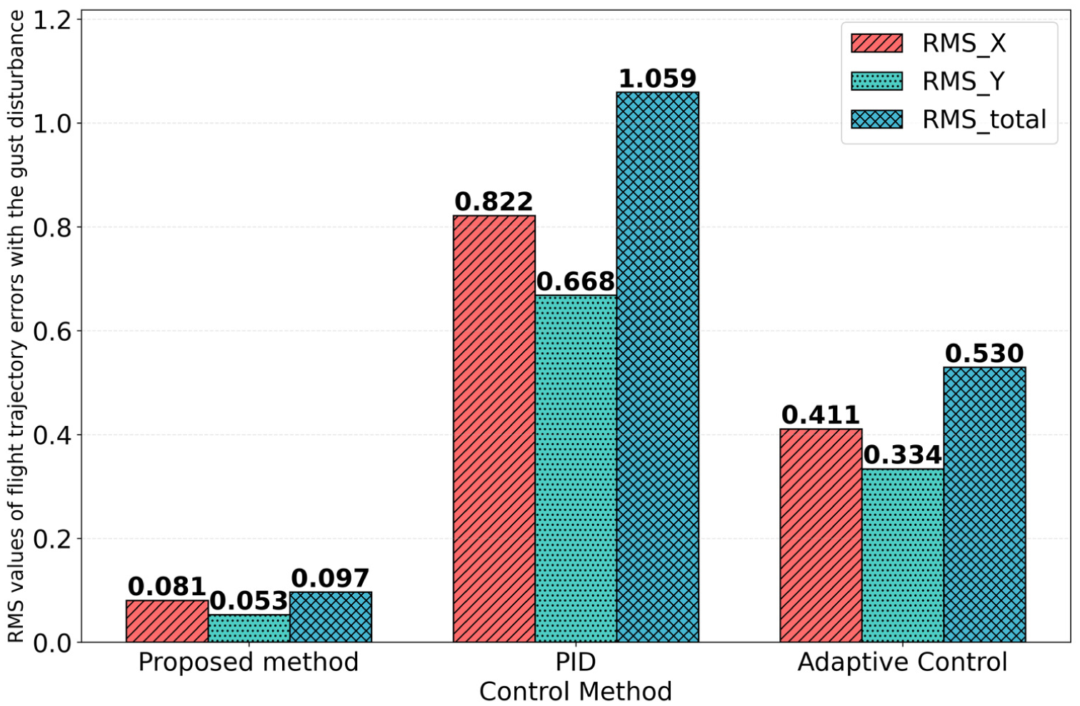
The RMS values of flight trajectory errors with the gust disturbance.
The PID controller operates via a passive feedback mechanism that reacts only after errors occur, suffering from integral windup and phase lag that induce substantial tracking error and significant overshoot. The noise sensitivity of the derivative term necessitates filtering, which exacerbates phase lag. By contrast, the active model control method leverages precise system models to predict future state trajectories, enabling anticipatory feedforward compensation and proactive disturbance rejection for zero-phase-error tracking with minimal overshoot. Explicit constraint handling within the optimization framework facilitates smooth control planning and steady-state error mitigation. Adaptive control methods exhibit performance intermediate between the reactive PID and the predictive active model control. Temporal delays in parameter convergence, coupled dual-loop dynamics between estimation and state regulation, and transient model inaccuracies during adaptation collectively degrade transient response, yielding moderate overshoot superior to PID yet inferior to the proposed method.
The proposed methodology comprises three core modules: POD, ASMF, and online optimization. Real-time feasibility on resource-constrained underground platforms demands rigorous complexity analysis. The POD module serves as a dimensionality reduction tool. Computational costs concentrate in the offline phase, where singular value decomposition of the snapshot matrix incurs O(
Conclusions
This study addresses the quadrotor control challenge in complex underground environments. A six-degree-of-freedom nonlinear dynamic model is developed. To mitigate gust effects, a real-time wind field prediction model is constructed based on wind speed sensor data and the POD method. In this framework, the prediction model and ASMF algorithm are combined, through which a multi-step incremental prediction mechanism is introduced. An active model correction framework is formulated as a constrained optimal control problem with online bias identification. By solving the above optimal control problem for the compensatory control inputs in real-time, effective control of the quadrotor in underground environments is achieved. Furthermore, convergence of the compensation algorithm is rigorously proved. Finally, the effectiveness of the algorithm is verified through numerical examples.
Footnotes
Appendix
The brief descriptions of the parameters in section 3.

| Parameter | Brief description | Parameter | Brief description |
|---|---|---|---|
| Local inertial frame origin | Attitude angle vector | ||
| Local inertial frame | The three-axis components of the body’s gravity | ||
| Body frame origin | the lift coefficient | ||
| Body frame | Rotational speed of rotor i | ||
| Local inertial frame axes (north-east-down) | Angular velocity vector in body frame pitch, yaw rate) | ||
| Body coordinate axes (front-right-down) | Euler angle rates | ||
| Rotation matrix from geodetic to body frame | The forces in x directions of the quadrotor | ||
| Rotation matrix from body to the local inertial frame | The forces in y directions of the quadrotor | ||
| Roll angle | The forces in z directions of the quadrotor | ||
| Pitch angle | The additional force generated in x directions by the external airflow | ||
| Yaw angle | The additional force generated in y directions by the external airflow | ||
| The lift generated by the rotor i | The additional force generated in z directions by the external airflow | ||
| The internal inclination angle of each rotor shaft | The angle of attack of the quadrotor | ||
| The wheelbase between adjacent rotors | The axial aerodynamic coefficient about | ||
| The length of the rotor shaft | The axial aerodynamic coefficient about | ||
| Mass of the quadrotor | The axial aerodynamic coefficient about and | ||
| Rotational speed of rotor i | The relative velocity of the external flow and the aircraft body | ||
| The lift coefficient | The reference area of the fuselage | ||
| The lift generated by the rotor i in the x-axe | The torque of the quadrotor in x directions | ||
| The lift generated by the rotor i in the y-axe | The torque of the quadrotor in y directions | ||
| The lift generated by the rotor i in the z-axe | The torque of the quadrotor in z directions | ||
| The torque generated by the rotor i | Position coordinates in geodetic frame | ||
| The torque lifts generated by the rotor i in the x-axe | Velocity components in geodetic frame | ||
| The torque generated by the rotor i in the y-axe | Acceleration components in geodetic frame | ||
| The torque generated by the rotor i in the z-axe | The overall external force vector | ||
| The component of the torque of each rotor in x direction | The velocity vector | ||
| The component of the torque of each rotor in y direction | Angular velocity vector | ||
| The component of the torque of each rotor in z direction | The inertias about the axes |
Handling Editor: Xiangwei Bu
Funding
The authors disclosed receipt of the following financial support for the research, authorship, and/or publication of this article: This study was supported by The National Natural Science Foundation of China (No. 12472001), Key Research and Development Project of Liaoning Provincial Department of Science and Technology, 2024JH2/10240004. This study was supported by the Tiandi Science & Technology Co., Ltd., for scientific and technological innovation and entrepreneurship. The project is entitled “Research on key technologies of UAV in a coal mine,” whose project number is 2019-TD-2-CXY007.
Declaration of conflicting interests
The authors declared no potential conflicts of interest with respect to the research, authorship, and/or publication of this article.