
Abstract
Metamaterials are employed to modulate the propagation of forced vibrations. The periodic structure inherently influences self-excited vibrations. Theoretical researches on the nonlinear dynamics and stability of a metamaterial rotor/seal system are presented in this paper. The nonlinear model of the metamaterial rotor/seal system is established. The instability threshold speed is calculated by the eigenvalue theory. Then the nonlinear differential equations are solved using the numerical integration method, and the dynamic behaviors including bifurcations are obtained. Also, the instability threshold speed is validated by the nonlinear responses. The results show that the local resonance bandgap generated by the metamaterial cannot forbid the propagation of the fluid-induced vibration in the rotor/seal system. The metamaterial can forbid the propagation of the instability vibration as incorporating the damping. This research provides a theoretical basis for suppressing self-excited vibrations in metamaterials and has potential for engineering applications.
Introduction
Rotor/seal systems in fluid machineries such as compressors and steam turbines have long-term vibrations during the operation process.1–4 Fluid-induced vibration in a rotor/seal system occurs when a small oscillation suddenly grows into a large and even destructive vibration. This is caused by the interaction between the fluid and the rotor as a key parameter, usually the rotational speed, approaches a critical value. The speed when the abrupt growth of amplitude happens is referred to as the instability threshold speed. It brings a lot of nonlinear phenomena such as periodic vibrations and bifurcations. They can cause instability vibrations with large amplitudes in the rotor/seal system. Therefore, the instability vibration caused by the fluid must be controlled.
Currently, modifying seal geometry and configuration remains the predominant strategy for suppressing instability vibrations in rotor/seal systems. Zhang et al. 5 introduced two kinds of the seal: the diaphragm labyrinth seal and hole diaphragm labyrinth seal to improve the vibration performance of a nonlinear rotor/seal system. Zhang et al. 6 presented a dovetail-shaped hole-pattern damping seal. The seal improved the effective damping, and mitigated the instability issues of the circular-shaped hole-pattern damping seal at low frequencies. The stability and bifurcations of complex vibrations in a brush-seal rotor system were studied by Xu et al. 7 Sun et al. 8 investigated a labyrinth seal considering the multiple frequencies elliptical whirling of the rotor and swirl brake. The rotor stability could be improved with increasing the circumferential solidity and radial length of the swirl brake. Zhang et al. 9 discovered high-order independent nonlinear vibrations in a rotor-bearing-finger seal system. Zhao et al. 10 proposed a honeycomb seal with a higher effective damping coefficient indicating a better stability of a rotor/seal system. Nonlinear dynamics of a rotor/seal system that considers the coupling of internal friction and labyrinth seal were investigated by Wei et al. 11 From the above literatures, it can be concluded that enhancing the effective damping and reducing the fluid circumferential velocity ratio are the primary strategies for optimizing seal design to increase the instability threshold of the rotor/seal system.
Recently, metamaterials have become a hot research topic for forbidding elastic wave propagation. The forbidden band can be classified into three types: the Bragg scattering, locally resonant and chaotic bands.12–14 The Bragg scattering band generates in periodic mass-spring, multi-layer, rod, beam, plate structures, and so on.12,15 Liang et al. 16 developed a class of motional two-dimensional hybrid Bragg-locally resonant meta-pipe. Mazzotti et al. 17 designed bio-inspired non self-similar hierarchical elastic metamaterial structures involving different scattering mechanisms. Beam-based coiled phononic crystals were presented by Willey et al. 18 This structure created effectively subwavelength Bragg bandgaps. The local resonant metamaterial is mainly composed of linear mass-spring oscillators. Elastic waves are prohibited to propagate within a specific frequency range due to the presence of local resonant units in a periodic structure. The specific frequency range is the local resonance bandgap. Zheng et al. 19 introduced a honeycomb metamaterial featuring a circular distribution of multiple mass-beam resonators to enhance the impact mitigation. Han et al. 20 proposed a mechanical memory metamaterial with tunability for the vibration attenuation in a desired frequency range. Wang et al. 21 addressed a type of piezoelectric metamaterial beams comprising unit cells with sub-cells undergoing the longitudinal vibration. Hu et al. 22 investigated a graded metamaterial beam for the broadband vibration suppression. The chaotic band is mainly formed by nonlinear metamaterials. Sheng et al.23,24 employed strongly nonlinear acoustic metamaterials to mitigate aeroelastic vibrations. Lou et al. 25 proposed an inertant nonlinear metamaterial beam for the ultra-low frequency broadband flexural wave attenuation. Fang et al. 26 investigated a nonlinear acoustic metamaterial plate and its sound radiation using experimental and theoretical method.
It should be noted that most current research on metamaterials is dedicated to forbid the propagation of the forced vibration, with an emphasis on achieving low-frequency and broadband performance. The application of metamaterials to forbid the propagation of self-excited vibrations in rotor systems remains challenging. In particular, effects of metamaterials on the nonlinear behaviors of rotor/seal systems after forbidding the propagation of the self-excited vibration require further investigation. The current application of the metamaterials in the self-excited vibration control is still in its preliminary stage, especially with a lack of systematic research in nonlinear rotor systems. A comparison between metamaterials and single degree of freedom dynamic vibration absorber for self-excited vibration control is instructive. The primary advantage of metamaterials lies in their spatial flexibility. They are not subject to the same geometric constraints often encountered in engineering applications. In contrast, the use of dynamic vibration absorber may be impractical in certain realistic scenarios due to space limitations or restrictions related to vibration levels.
This paper introduces metamaterials into a rotor/seal system to investigate the dynamic behavior and stability of self-excited vibrations induced by seal fluid. This work aims to extend fundamental research on the application of metamaterials in rotor systems. The remainder of the paper is arranged as follows. Section “Model of metamaterial rotor/seal system” presents the dynamic model of the metamaterial rotor/seal system. Section “Instability threshold speed” addresses the instability threshold speed of the system. Theoretical results are presented and discussed in Section “Numerical simulations,” followed by an analysis of the influence of damping in Section “Influence of damping.” Conclusions are drawn in Section “Conclusions.”
Model of metamaterial rotor/seal system
Figure 1 describes the model of a metamaterial rotor/seal system. Only the bending vibration is considered. The metamaterial is a periodic elastic structure that influences vibration propagation through the local resonance mechanism. The local resonance unit within such the metamaterial can be modeled as is a mass-spring system. S local resonance units are attached to the shaft in the form of the rotor absorber. 27 The position is not considered. The improved Jeffcott rotor and Muszynska’s nonlinear seal force models28,29 are employed to simulate real rotor dynamics characteristics while simplifying the calculations. There are two advantages using the proposed dynamic model. First, it can accurately describe the dynamic characteristics of the rotor/seal system. Second, the calculation is simple due to the relatively limited degree of freedom. The fact that it cannot take into account the influence of the position of the units is the limitation of this model.

Schematic diagram of a metamaterial rotor/seal system: (a) metamaterial rotor/seal system, (b) fluid force model, and (c) equivalent model.
The equations of motion for the metamaterial rotor/seal system are as follows:


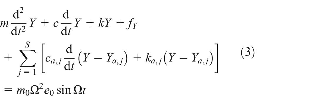

where m, c and k are the mass, damping and stiffness coefficients of the rotor, respectively. m0 and e0 are the eccentric mass and eccentricity distance, respectively. Ω is the rotational speed. X and Y are the displacements of the rotor in the x and y directions, respectively. m a,j , c a,j and k a,j are the mass, damping and stiffness coefficients of the jth local resonance unit, respectively. X a,j and Y a,j are the displacements of the jth local resonance unit in the x and y directions, respectively. f X and f Y are the components of the Muszynska’s nonlinear seal force in the x and y directions, respectively.
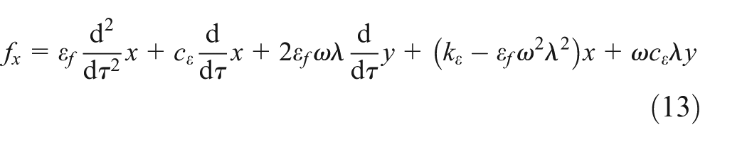
The expressions of the nonlinear seal force are as follows:
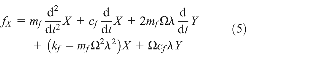

where m f is the fluid inertia coefficient. λ is the fluid circumferential average velocity ratio. c f and k f are the fluid film radial damping and stiffness coefficients, respectively.
The nonlinear terms in the nonlinear seal force are as follows:

where c0, k0, λ0, n and b are the seal force parameters. e f is the seal clearance. The parameters are described in detail in Muszynska. 29
To define the dimensionless parameters:
x, y: the dimensionless displacements of the rotor in the x and y directions.
ω:the dimensionless rotational speed.
τ: the dimensionless time.
m e : the dimensionless eccentric mass.
x j , y j : the dimensionless displacements of the jth local resonance unit in the x and y directions.
ωj: the dimensionless natural frequency of the jth local resonance unit.
m j : the dimensionless mass of the jth local resonance unit.
εf: the dimensionless fluid inertia coefficient.
c ε, kε: the dimensionless seal force parameters.
εe: the dimensionless seal clearance.

where γ is the natural frequency of the rotor. ζ is the damping ratio of the rotor. γ a,j is the natural frequency of the jth local resonance unit. ζ j is the damping ratio of the jth local resonance unit.
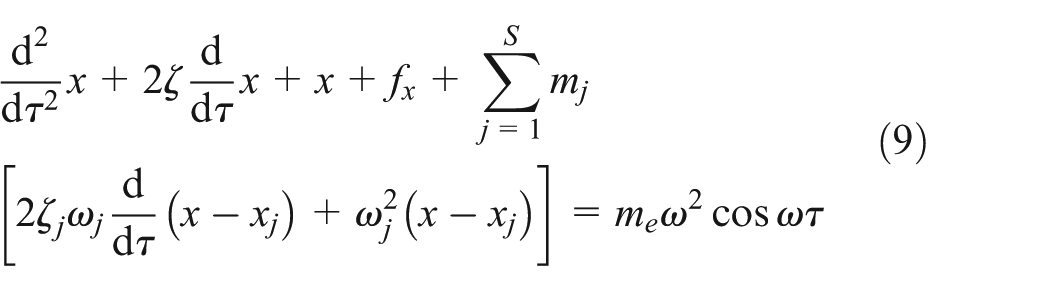
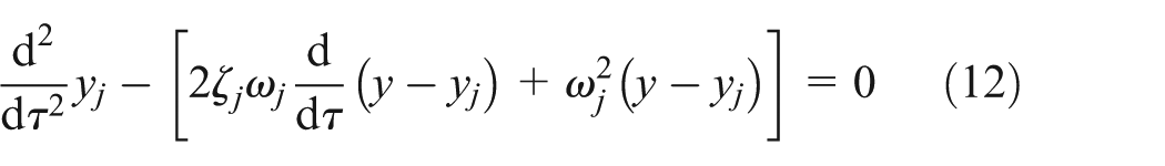
The dimensionless equations are as follows:


where

Instability threshold speed
The fluid inertia coefficient and nonlinear terms are neglected due to their negligible magnitude. In calculating the instability threshold speed, the unbalanced force is also assumed to be zero. The solutions of the linearized equations are given as follows:

Substituting the above equation into equations (8) to (11). The equations are simplified as follows:


Assuming that the solutions of the linearized equations are as follows:

where μ is the eigenvalue of the system. A and A j are the integration constants of the system.
Substituting the above equation into equations (16) and (17). Two linear equations with A and A j as variables are obtained:
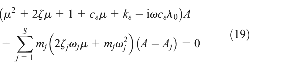

The characteristic equation can be obtained:
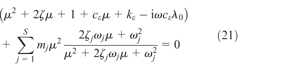
Assuming that the mass, natural frequency and damping ratio of the local resonance unit to be identical (m j = m a , ω j = ω a , and ζ j = ζ a ). The characteristic equation can be simplified as:

where
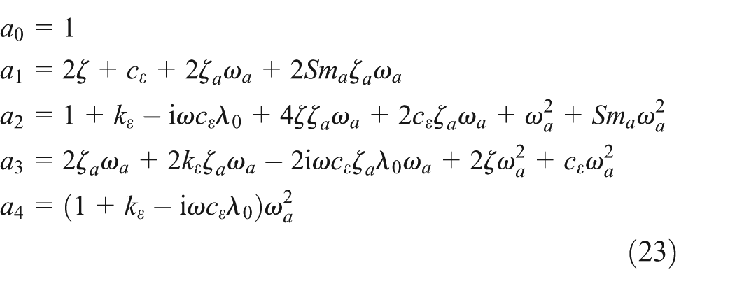
According to the Routh-Hurwitz stability criterion, 30 the instability threshold speed ω i of the rotor system can be obtained from the above expressions.
Numerical simulations
The parameters of the rotor and nonlinear seal force are m = 1 kg, c = 10 Nm/s, k = 400 N/m, m0 = 0.01 kg, e0 = 0.01 m, m f = 1 × 10⁻⁶ kg, c0 = 0.5 N/m, k0 = 0 N/m, λ0 = 0.48, n = 2, b = 0.5 and m a = 0.002 kg. The dimensionless parameters are calculated: ζ = 0.025, m e = 0.01, ε f = 1 × 10⁻⁶, cε = 0.5 and kε = 0.27,28 Taking the total mass ratio is Sm a = 0.01 and the number of local resonance units is S = 5. ω a and ζ a can be obtained from the characteristic equation. Figure 2 presents a contour plot of the instability threshold speed of the metamaterial rotor/seal system as a function of ω a and ζ a , obtained from equation (22). It can be seen that the instability threshold ω i reaches a maximum value of 2.67 at ω a = 0.99 and ζ a = 0.05. Accordingly, the parameters of the local resonance unit are selected as ω a = 0.99 and ζ a = 0.05.

Contour of the instability threshold of the metamaterial rotor/seal system varying with ω a and ζ a .
The instability threshold speed of the metamaterial rotor/seal system is calculated using equation (22). In Figure 3, the red star and blue circle indicate the eigenvalues of the rotor/seal system before and after the introduction of the metamaterial, respectively. As shown in Figure 3(a), the frequency of the instability vibration shifts from 1 to 1.02. Meanwhile, Figure 3(b) shows that the instability threshold speed increases from 2.29 to 2.67, corresponding to a 16.59% improvement.

Comparison results of the eigenvalues and real parts varying with the speed ω between the rotor/seal and metamaterial rotor/seal systems: (a) eigenvalues and (b) eigenvalue real parts varying with the speed ω.
Newmark numerical integration method is employed to solve equations (9) to (12) due to the complex nonlinear terms. The numerical algorithm is unconditionally convergent as the values of the parameters β ≥ 1/4 and δ ≥ 1/2. 31 While unconditional stability ensures that the numerical solution does not diverge, it does not guarantee accuracy. Therefore, the initial values should be chosen to approximate the true solution of the rotor/seal system as closely as possible. In this section, the initial conditions for displacement, velocity, and acceleration are all set to 1 × 10⁻⁵. These values are chosen to be close to zero, given that zero is itself a solution of the system. The integration time per period is set to p = 100, and the time step is h t = 2π/ω/p. The converge criterion is defined by the ratio of the Euclidean norm of the displacement increment at the current time step to that at the next time step. The iteration procedure continues until this ratio falls below a specified tolerance of 10−8.
Rotational speed is a key parameter in nonlinear rotor/seal systems and is therefore selected as the bifurcation parameter. For each rotational speed, 2000 periods are computed, with the final 200 periods retained as steady-state solutions for bifurcation analysis. The Poincaré section provides a geometric approach to simplify the analysis and visualization of periodic, quasi-periodic, and n-periodic motions, among others. The Poincaré map is constructed by sampling one point per period of the periodic solution. Figure 4 presents the bifurcation diagrams and amplitude-frequency response curves for both the rotor/seal system and metamaterial rotor/seal system. As before, the red star and blue circle denote the system before and after the introduction of the metamaterial, respectively. In the bifurcation diagram of the rotor/seal system, only a single point appears at each rotational speed, indicating single-periodic vibration for ω < 2.31. The vibration response becomes quasi-periodic or multi-periodic when ω ≥ 2.31. It is necessary to make a further judgement by Poincaré map. At this threshold, the effect of the nonlinear seal force becomes evident, and ω = 2.31 is identified as the instability threshold speed of the rotor/seal system.

Comparison results of the bifurcation and amplitude-frequency response between the rotor/seal and metamaterial rotor/seal systems: (a) bifurcation diagram and (b) amplitude-frequency response.
For the metamaterial rotor/seal system, single-periodic vibration is maintained for ω < 2.69, while quasi-periodic or multi-periodic responses emerge at ω ≥ 2.69. Thus, ω = 2.69 corresponds to the instability threshold speed of the metamaterial-enhanced system. Notably, the introduction of the metamaterial increases the instability threshold speed by approximately 16.45%. The metamaterial is capable of completely suppressing the propagation of the instability vibration, within the rotational speed range between ω = 2.31 and ω = 2.69 (highlighted by the gray rectangle).
Additionally, the discrepancy between the eigenvalue analysis and numerical integration is approximately 0.75%, indicating that the instability threshold speed derived from the characteristic equation is both acceptable and relatively conservative.
The vibration response of the system is furtherly analyzed at rotational speeds of ω = 2.2, ω = 2.6 and ω = 3, respectively, as shown in Figures 5 to 7. In these figures, the blue star and red circle denote the frequency spectrum, orbit of the rotor and Poincaré map for the rotor/seal system and metamaterial rotor/seal system, respectively.
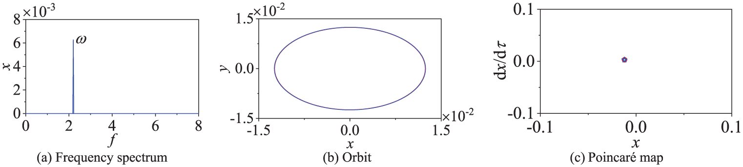
The frequency spectrum, orbit and Poincaré map of the rotor/seal (red) and metamaterial rotor/seal (blue) systems at ω = 2.2: (a) frequency spectrum, (b) orbit, and (c) Poincaré map.
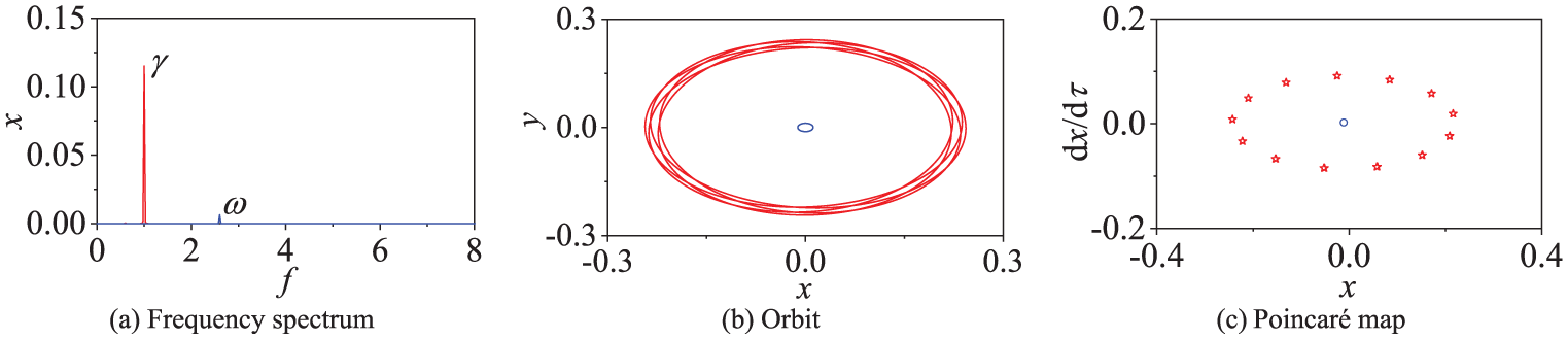
The frequency spectrum, orbit and Poincaré map of the rotor/seal (red) and metamaterial rotor/seal (blue) systems at ω = 2.6: (a) frequency spectrum, (b) orbit, and (c) Poincaré map.
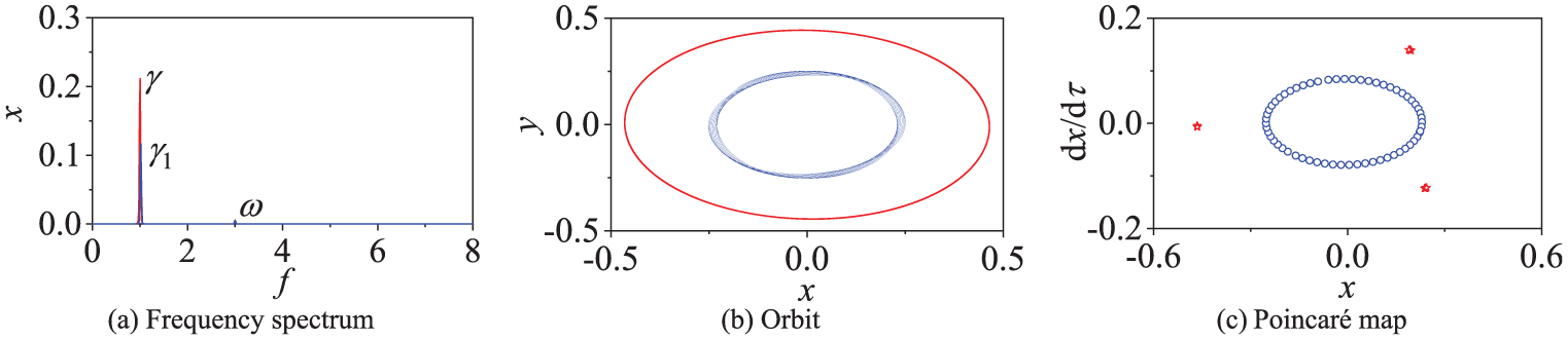
The frequency spectrum, orbit and Poincaré map of the rotor/seal (red) and metamaterial rotor/seal (blue) systems at ω = 2.3: (a) frequency spectrum, (b) orbit, and (c) Poincaré map.
At ω = 2.2, both systems exhibit a single point in their Poincaré maps, indicating single-periodic vibration at the excitation frequency ω. The corresponding rotor orbits are regular.
As the rotational speed increases to ω = 2.6, the ratio of the rotor natural frequency (γ = 1) to the excitation frequency (ω = 2.6) is ω/γ = 1/2.6, an irrational number. In the rotor/seal system, the Poincaré map reveals a closed curve formed by an infinite number of points, characteristic of quasi-periodic vibration involving both the excitation frequency ω and the natural frequency γ. The rotor orbit becomes irregular. In contrast, the quasi-periodic response is absent in the metamaterial rotor/seal system. The instability vibration is completely suppressed, and only a synchronous response at the excitation frequency ω remains.
At ω = 3, the Poincaré map of the rotor/seal system displays three isolated points, corresponding to a period-three motion. The frequency ratio ω/γ = 1/3 is rational, and the quasi-periodic response is replaced by three-periodic vibration. The rotor orbit becomes regular again, as the amplitude of the natural frequency component γ dominates that of the rotational frequency ω. For the metamaterial rotor/seal system, the response is qualitatively similar, but the instability vibration frequency shifts to the first-order natural frequency of the modified system, γ1 = 1.02. The ratio ω/γ1 = 1.02/3 is irrational, resulting in a quasi-periodic response characterized by a closed curve in the Poincaré map. Notably, the vibration amplitude of the metamaterial rotor/seal system is smaller than that of the original system.
The validity of the results is discussed as follows. Three types of periodic solutions (single-periodic, quasi-periodic, and n-periodic) are observed in the rotor/seal system. They are consistent with those reported in Cheng et al. 28 The instability threshold speed is verified using both eigenvalue analysis and the Routh-Hurwitz stability criterion. The discrepancy between the eigenvalue calculation and numerical integration is approximately 0.75%, indicating an acceptable level of accuracy.
Influence of damping
Metamaterials do not inherently serve as a source of damping. Rather, they rely on the local resonance mechanism to affect the propagation of the vibration. 32 It is important to note that the vibration mentioned in the previous sentence is the forced vibration by eccentric forces. In contrast, vibrations arising from seal (fluid) force are characteristic of the self-excited vibration. Accordingly, the case without damping is considered in the following discussion.
Setting the damping ratio ζ j = 0 in equation (21), the characteristic equation can be rewritten:
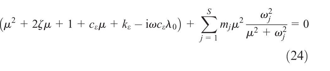
Figure 8 illustrates the variation of the instability threshold speed of the metamaterial rotor/seal system (without damping) as a function of the natural frequency ω a of the metamaterial unit, as obtained from equation (24). The results indicate that the instability threshold speed increases with ω a and asymptotically approaches the instability threshold speed of the original rotor/seal system (ω i = 2.29).

Instability threshold speed of the metamaterial rotor/seal system without damping varying with ω a .
For a more direct comparison with Figure 4, the natural frequency of the metamaterial unit is set to ω a = 0.99. Figure 9 presents the bifurcation diagram and amplitude-frequency response curve of the metamaterial rotor/seal system with and without damping, obtained from equations (8) to (11). In the figure, the blue star and black square denote the metamaterial rotor/seal system with and without damping, respectively. It can be observed that the bandgap generated by the metamaterial is located near the resonance region. In other words, the propagation of vibration within the frequency range around the rotor natural frequency γ is suppressed. Nevertheless, the instability vibration occurring at the rotor natural frequency γ (Figure 6) is not suppressed. In fact, the instability threshold speed is decrease (from 2.29 to 2.1). This indicates that introducing damping into the metamaterial is necessary to suppress the propagation of instability vibrations in the metamaterial rotor/seal system. However, the inclusion of damping also weakens the ability of the locally resonant bandgap to influence the propagation of the forced vibration, as shown in Figures 4(b) and 9(b). This is a contradictory choice for the rotor/seal system.

Comparison results of the bifurcation and amplitude-frequency response of the metamaterial rotor/seal system with and without damping: (a) bifurcation diagram and (b) amplitude-frequency response.
In addition, based on the local resonance mechanism, the forbidden band generated by the undamped metamaterial is near ω = 1. The bandgap boundaries can be determined using the following expressions 33 :

The propagation of the eccentric vibration is forbidden in the bandgap. The amplitude has significantly decreased.
Conclusions
This paper investigates the nonlinear dynamic characteristics and stability of the metamaterial rotor/seal system. Theoretical analysis results indicate the local resonance bandgap generated by the metamaterial alone is insufficient to suppress the propagation of fluid-induced vibrations. In fact, without damping, the metamaterial may even reduce the instability threshold speed, thereby increasing the risk of instability vibration. Introducing the damping into the metamaterial can increase the instability threshold speed by approximately 16% and effectively eliminate the instability vibration. These findings highlight both the potential and the design trade-offs associated with applying metamaterials in rotor/seal systems for self-excited vibration control. The main contribution of this paper is demonstrating the feasibility of suppressing self-excited vibrations in rotor/seal systems using metamaterials. However, the limitation of the paper is that it cannot take into account the influences of the position and number of the local resonance unit on the rotor nonlinear behavior due to the proposed model and method. This study focuses on the influence of metamaterials on the propagation characteristics of instability vibrations in rotor/seal systems. Further research can be extended to examine the bandgap performance of metamaterials in suppressing other forms of self-excited vibration propagation. In the future, metamaterials hold potential for practical application in mitigating fluid-induced vibrations and enhancing the stability of rotor/seal systems.
Further works include the effects of the defect state of the metamaterial on the self-excited vibration propagation in the rotor/seal system and the comparisons between the theoretical research and experiment for the effectiveness on the rotor test rig. We are considering the use of a liquid-filled rotor to achieve the desired characteristics of the rotor/seal system.
Footnotes
Appendix
Handling Editor: Divyam Semwal
Funding
The authors disclosed receipt of the following financial support for the research, authorship, and/or publication of this article: This research was funded by the National Natural Science Foundation of China, Grant Number 52475094.
Declaration of conflicting interests
The authors declared no potential conflicts of interest with respect to the research, authorship, and/or publication of this article.
Data availability statement
No new data were created or analyzed in this study.