
Abstract
Against the backdrop of Industry 4.0 and emerging Industry 5.0 driving manufacturing toward customized production, complex engineering systems feature high dynamics and complexity. Traditional single dynamic simulation tools face challenges like difficult cross-platform integration. To address the demand for multi-source heterogeneous digital twin modeling, this study proposes the Adams-FMI-Unity co-simulation technical architecture and agile implementation method: building a parametric multi-body dynamic model with Adams, achieving standardized integration of multi-source heterogeneous models via the FMI 2.0 standard, and enabling personalized real-time visual interaction based on the Unity engine. Validated with a crank-slider mechanism, the simulation shows high fidelity with theoretical calculations, achieving RMSE of 0.0015 m, MAE of 0.0012 m, and MAPE less than 0.2%. Interactivity verification proves that dynamic simulation can be realized by adjusting driving parameters. The main contributions of this work include: (1) a novel layered co-simulation architecture integrating Adams multi-body dynamics with Unity visualization through FMI 2.0, enabling real-time interactive digital twin applications; (2) a master-slave time synchronization mechanism ensuring consistent data exchange between heterogeneous simulation environments; and (3) experimental validation demonstrating the feasibility of the proposed framework for rapid product verification and customer interaction in customized production scenarios. This provides practical basis for subsequent industrial applications.
Keywords
Introduction
Currently, the global manufacturing industry is undergoing a profound transformation from Industry 3.0 to Industry 4.0. More recently, Industry 5.0 has emerged as an evolution of this digital transformation, emphasizing human-centric approaches, sustainability, and resilience in industrial settings. 1 Unlike Industry 4.0 which focuses primarily on automation and data exchange, Industry 5.0 places greater importance on the collaboration between humans and intelligent machines, recognizing that technology should serve human needs while promoting sustainable development. 2 The rapid growth of personalized demand has driven the continuous expansion of the customized manufacturing market scale. McKinsey research report predicts that the global customized manufacturing market size will reach 5 trillion US dollars by 2030, among which the customized demand in high-end equipment manufacturing, aerospace, automotive industry, and other fields is growing most rapidly. 3 As the core driving force of the Fourth Industrial Revolution, Industry 4.0 is reshaping the face of manufacturing through the in-depth integration of intelligent technologies. 4 Compared with the traditional mass standardized production mode, customized production requires manufacturing systems to quickly respond to personalized product needs while maintaining economies of scale, realizing flexible manufacturing of “batch size one.” 5 However, manufacturing systems in the customized production environment exhibit high complexity and dynamic characteristics. Each customized product has significant differences in geometric configuration, material properties, motion mechanisms, control strategies, etc., leading to frequent reconstruction and parameter adjustment of manufacturing equipment. 6 According to Industry 4.0-related research, the complexity of modern manufacturing systems mainly stems from the wide application of flexible automation and robot technology, which makes the analysis and optimization of manufacturing systems extremely difficult. 7 This fundamental transformation of the production mode poses unprecedented challenges to the design, verification and optimization of manufacturing systems. Especially with the continuous improvement of product complexity and the increasing shortening of development cycles, traditional product design, analysis, verification, and optimization methods have been difficult to meet the agile response needs of customized production. 7
Physical simulation technology, as an important bridge connecting the design layer and the management layer, can provide strong technical support for customized production. 8 The needs of physical simulation in customized production are mainly reflected in the following aspects: first, the demand for rapid product verification—the diversity of customized products requires the simulation system to quickly build targeted models to verify product performance under different configurations; second, the demand for multi-physics coupling analysis—customized products often involve the in-depth integration of multiple professional fields such as machinery, electronics, hydraulics, and control, requiring cross-domain co-simulation capabilities; third, the demand for real-time interactive verification—the customized process with deep customer participation requires intuitive simulation result display and real-time feedback mechanisms; finally, the demand for cost-benefit optimization—achieving high-quality product design and verification under limited time and cost constraints. Among various physical simulation technologies, dynamic simulation is particularly important because it can accurately describe the dynamic behavior of mechanical systems under the action of forces and motions. Uhlemann et al. 9 pointed out that more than 80% of customized products in modern cyber-physical production systems involve complex mechanical motion mechanisms, and their performance directly determines the functional realization and user experience of products. By solving complex multi-body dynamic equations, dynamic simulation technology can accurately predict key performance indicators such as motion trajectory, load distribution, and vibration characteristics of mechanical systems, providing a scientific basis for the mechanical structure optimization of customized products. 10 Especially in high-end manufacturing fields such as aerospace, automotive industry, and robot technology, multi-body dynamic simulation has become an indispensable core tool for product design. 11 However, traditional single dynamic simulation tools face significant limitations in meeting the complex needs of customized production. First, difficult cross-platform integration—simulation tools in different professional fields often adopt different modeling languages and data formats, making it difficult to achieve seamless integration; second, limited real-time performance—complex dynamic calculations often take a long time, making it difficult to support real-time customer interaction needs12; third, insufficient visualization—traditional dynamic simulation tools mainly focus on calculation accuracy, and are relatively weak in user interaction and result display. These limitations make it difficult for traditional simulation methods to give full play to their application value in customized production.
To address the above challenges, digital twin and multi-source heterogeneous model integration technologies have emerged. Digital twin refers to the technology of building a digital mapping twin in the information space based on data collection, fusion and interactive feedback of physical objects. 13 The difference from traditional 3D visualization lies in the real-time calculation and analysis of on-site data, so as to obtain accurate cognition and make decisions. Its advantage lies in the synchronization between the virtual twin and the physical entity, the real-time update and interaction of data, integrating multiple data sources such as physical systems, equipment status, and on-site environment. Digital twin technology integrates heterogeneous models of multiple disciplines, multiple scales, multiple physical fields, multiple time-space, and different granularities, and achieves high-precision simulation through standardized interfaces for data exchange between different simulation tools, thereby reflecting the full life cycle process of the corresponding physical equipment. 14
The primary objective of this research is to develop a dynamic simulation system that addresses the challenges of cross-platform integration, real-time performance, and intuitive visualization for customized production scenarios. Specifically, this work aims to: (1) design a layered co-simulation architecture that systematically integrates Adams multi-body dynamics modeling, FMI-based model integration, and Unity 3D visualization; (2) implement a master-slave time synchronization mechanism ensuring consistent data exchange between heterogeneous simulation environments; (3) validate the proposed framework through a representative mechanical system case study; and (4) discuss the framework’s potential for extension to more complex industrial applications.
Research progress on multi-source heterogeneous models and digital twin
Research progress on multi-source heterogeneous models
Multi-source heterogeneous models refer to models involving different modeling languages, different subject areas, and different modeling platforms. In the design of the digital twin framework for complex systems, it is necessary to integrate sub-system models from different scientific fields through multi-source heterogeneous modeling methods, and simulate complex systems through co-simulation technology. Common Multi-source Heterogeneous Models include multi-source heterogeneous modeling methods based on compatible software interfaces, multi-source heterogeneous modeling methods based on High Level Architecture (HLA) specifications, and multi-source heterogeneous modeling methods based on the Functional Mock-up Interface (FMI) standard.
The key to realizing the multi-source heterogeneous modeling method based on compatible software interfaces is that the modeling platforms of various Multi-source Heterogeneous Models need to have mutually compatible interfaces. Herrera-Cordero et al. 15 established a dynamic-control multi-source heterogeneous simulation model of a Single-Wheel Pendulum Robot (SWROB) with inertial motion drive using ADAMS/Matlab software. This work demonstrates that Adams has been successfully applied in heterogeneous co-simulation scenarios, integrating multi-body dynamics with control system design. Tong et al. 16 established a multi-source heterogeneous simulation model of the elevation servo device using Ansys, Adams, and EASY5 simulation software, and studied the dynamic characteristics of a rocket launcher’s elevation servo device during gun adjustment. Juan et al. 17 established a series six-degree-of-freedom multi-source heterogeneous simulation model through Adams, AMESim, and Simulink, and conducted research on the simulation analysis of complex mechatronic-hydraulic integrated systems. Qiang et al. 18 established a dynamic-electromagnetic-fluid Multi-source Heterogeneous Model using Adams, Ansys Magnetic, and Ansys Flotran.
In recent years, with the continuous improvement of the functions of commercial simulation software, the co-simulation method based on software interfaces has developed rapidly. Kim et al. 19 proposed a vehicle dynamics co-simulation framework based on MATLAB/Simulink and Adams, realizing the effective integration of the vehicle control system and the dynamic system. Li et al. 20 developed a multi-source heterogeneous simulation platform for hydraulic systems based on AMESim and MATLAB, realizing the seamless integration of models from different professional fields through standardized interfaces. Wang et al. 21 presented the design and simulation of a 6-DOF Stewart parallel lifting platform for assisted tea leaf picking using Adams, demonstrating the application of multi-body dynamics simulation in agricultural robotics.
The multi-source heterogeneous modeling method based on the High Level Architecture specification separates the main program and each subprogram environment based on the RTI support environment, and establishes a model by developing the interface between the subprogram and the main program. Bohan et al. 22 realized the CPS prototype system based on the data interaction model and High Level Architecture (HLA)/Data Distribution Service (DDS) system middleware, verified the model availability and compared the message compression performance. Wang et al. 23 constructed a distributed manufacturing system simulation platform based on the HLA standard, realizing the simulation analysis of multi-factory collaborative manufacturing through data interaction between federates. Zhang et al. 24 proposed a multi-physics coupling simulation architecture based on HLA, which was successfully applied to the multi-disciplinary simulation of aero-engines, significantly improving the simulation accuracy and computational efficiency.
The Functional Mock-up Interface (FMI) standard provides a unified interface specification for the integration of Multi-source Heterogeneous Models. The FMI standard supports the import and export of (FMUs, realizing model exchange and co-simulation between different simulation tools. 25 Gomes et al. 26 developed a multi-domain co-simulation platform based on the FMI standard, supporting the integrated simulation of models in multiple professional fields such as machinery, electronics, and hydraulics. Benedikt et al. 27 applied the FMI standard to the automotive industry, constructing a multi-source heterogeneous simulation model of engine-transmission system-body dynamics, realizing vehicle-level co-simulation. Awais et al. 28 developed a building energy consumption simulation system based on the FMI 2.0 standard, integrating HVAC system, building thermodynamics model, and control system model.
With the development of artificial intelligence and big data technology, emerging multi-source heterogeneous modeling methods are constantly emerging. Agent model technology based on machine learning provides a new idea for rapid simulation of complex systems. 29 Liu et al. 30 proposed a multi-physics agent model based on deep learning, which significantly reduced the computational complexity of multi-source heterogeneous simulation. Chen et al. 31 developed a model order reduction method based on Proper Orthogonal Decomposition (POD), which greatly improved the real-time performance of multi-source heterogeneous simulation under the premise of ensuring simulation accuracy. In addition, Wang et al. 32 constructed a cloud-based multi-source heterogeneous simulation service system, supporting remote collaborative modeling and large-scale parallel simulation.
Research progress on digital twin
The concept of Digital Twin was first proposed by Professor Michael Grieves from the University of Michigan in the United States in 2003, and has received extensive attention and development in the industry and academic circles since then. 33 Digital Twin makes full use of data such as physical models, sensor updates, and operation history, integrates multi-disciplinary, multi-physical quantity, multi-scale, and multi-probability simulation processes, and completes the mapping in the virtual space, thereby reflecting the full life cycle process of the corresponding physical equipment. 14
Tao et al. 34 proposed the five-dimensional digital twin model, which comprises physical entity, virtual model, services, data, and connection components, providing a comprehensive theoretical framework for digital twin implementation in manufacturing. This model has been widely adopted and extended by researchers worldwide, forming the foundation for numerous industrial applications. Lu et al. 35 conducted an extensive review of digital twin-driven smart manufacturing, analyzing the connotation, reference models, applications, and research issues in this domain. Their work identified critical challenges including data processing, model integration, and real-time synchronization, which remain central concerns for digital twin system development.
Mourtzis et al. 36 have made significant contributions to edge-cloud computing paradigms for digital twin applications. Their research addresses the computational challenges of real-time digital twin operations by distributing processing tasks between edge devices and cloud servers, thereby balancing latency requirements with computational capabilities. This is particularly relevant for industrial scenarios where real-time responsiveness is critical.
In terms of the combination of dynamic simulation, visualization technology and digital twin, many innovative research results have emerged in recent years. Leng et al. 37 proposed a digital twin modeling method for material flow based on physical simulation, simulating the physical interaction between workpieces and material handling systems through a physical engine, providing important technical support for the digital twin of manufacturing systems. Zhang et al. 38 developed a digital twin platform for complex mechanical systems, integrating multi-rigid body dynamics, finite element analysis, and real-time data collection functions, realizing real-time monitoring and predictive maintenance of equipment status. Rasheed et al. 39 reviewed the multi-physics modeling technology in digital twin, pointing out that multi-disciplinary optimization and uncertainty quantification are the key technical directions for the development of digital twin. Chen et al. 40 proposed a digital twin evaluation method for manufacturing systems based on system dynamics, providing a new idea for the performance optimization of manufacturing systems. Liu et al. 41 proposed a digital twin visualization method for manufacturing systems based on virtual reality technology, enhancing the user experience of the digital twin system through 3D visualization and interaction technology. Wang et al. 42 combined augmented reality technology with digital twin, developed an AR-assisted system for equipment maintenance, realizing the seamless integration of virtual information and physical environment. In predictive maintenance applications, high-fidelity digital twin models of equipment are established to realize fault prediction and remaining life assessment. 43 In terms of fatigue life prediction, the stress-strain history of key components under actual working conditions is calculated using multi-body dynamic simulation capabilities to achieve accurate prediction of fatigue life. 44 A wear prediction model is established based on the Archard wear theory, and the wear amount is calculated by obtaining the contact force and sliding distance through dynamic simulation. 45 The prediction results are displayed through 3D visualization, and the health status of components is displayed using color mapping. 46 Recent advances in AI-driven digital twin have opened new possibilities for intelligent simulation and optimization. Machine learning algorithms have been integrated with digital twin systems to enable predictive maintenance, process optimization, and adaptive control. 47 Deep reinforcement learning has been applied to manufacturing process optimization within digital twin frameworks, demonstrating significant improvements in production efficiency. 48
As the world’s most famous and widely used multi-body dynamics (MBD) software, Adams uses the Lagrange multiplier method to solve the dynamic equations of constrained multi-body systems, and can handle simulation problems involving complex physical phenomena such as rigid bodies, flexible bodies, and contact collisions. 49 While Adams has been successfully applied in various heterogeneous co-simulation scenarios as demonstrated by previous studies,15,21 the specific integration of Adams with Unity 3D through FMI for real-time interactive visualization in digital twin applications represents a novel contribution of this work. The innovation lies not in the individual components but in the systematic integration that enables real-time interactive digital twin functionality for customized production scenarios. Therefore, aiming at the rapid simulation verification needs of complex engineering systems driven by customized production, this paper analyzes the architecture and agile implementation method of the Adams-FMI-Unity co-simulation technology. By integrating parametric multi-body dynamic simulation, standardized model agile integration and personalized real-time visualization technology, it combines the professional advantages of Adams in multi-body dynamic modeling, the standardization capability of the FMI standard in cross-platform model integration, and the technical leadership of Unity in real-time visualization and interactive experience, 50 constructing a digital twin platform supporting rapid simulation verification and customer interaction of customized products. The correctness and interactivity of the simulation are verified through the crank-slider mechanism simulation case, providing a theoretical basis for the in-depth application and industrial development of digital twin technology in the field of customized production.
Modeling of dynamic simulation system
System architecture
Based on the demand for multi-source heterogeneous model integration, this paper proposes an Adams-FMI-Unity multi-source heterogeneous dynamic digital twin simulation system architecture. This architecture makes full use of the multi-body dynamic modeling capability of Adams, the cross-platform model exchange capability of the FMI standard, and the 3D visualization rendering capability of Unity, constructing a digital twin simulation platform supporting real-time interaction.
Overall architecture design
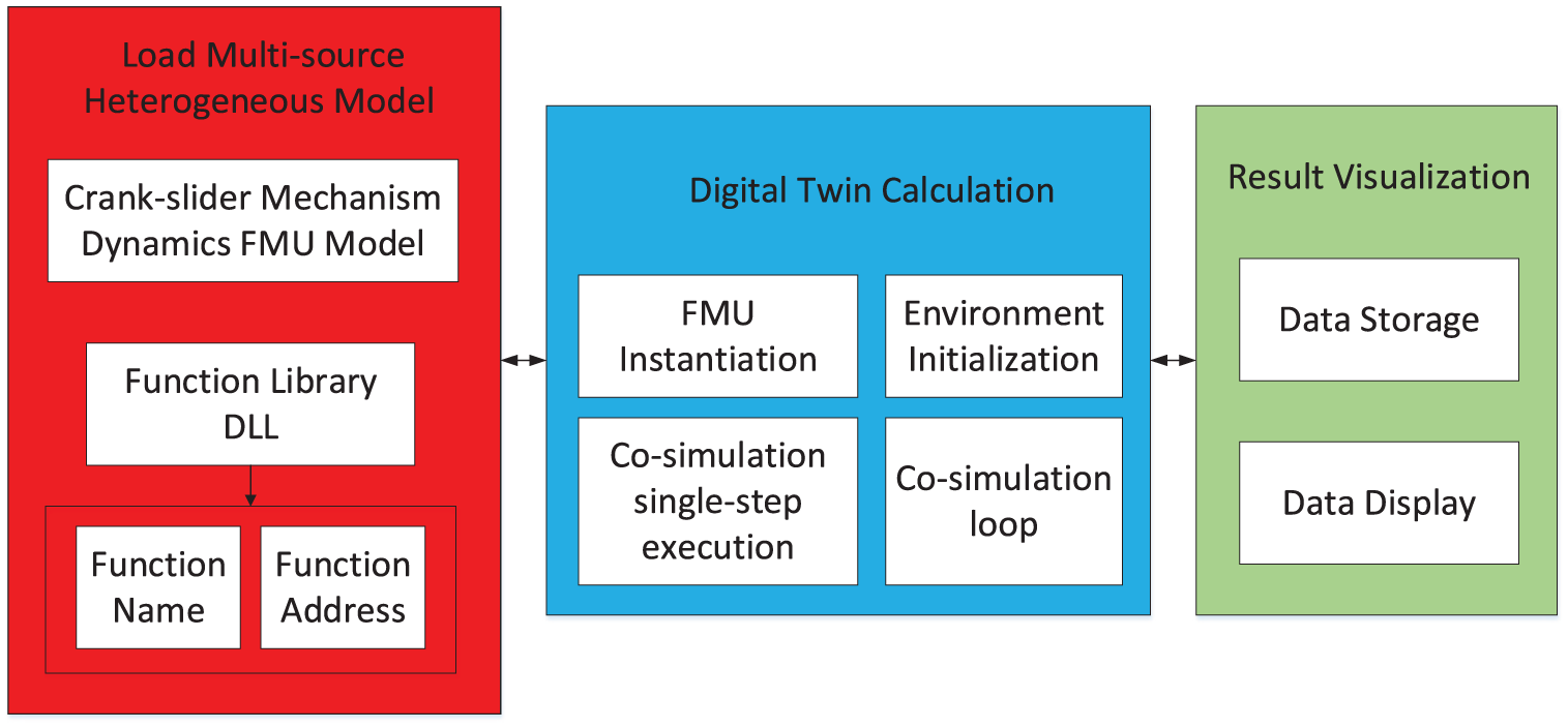
The Adams-FMI-Unity dynamic simulation system adopts a layered architecture design, as shown in Figure 1. The system architecture mainly includes three layers: the physical modeling layer, the model integration layer, and the visualization presentation layer. 51 Additionally, the enhanced architecture incorporates auxiliary modules for error handling, fault tolerance, and performance monitoring to address practical industrial deployment considerations.

Dynamic simulation system architecture design.
The physical modeling layer is responsible for the accurate physical modeling of complex mechanical systems. With Adams as the core, this layer establishes a complete physical model including multi-rigid body dynamics, rigid-flexible coupling dynamics, and constraint relationships. As a leading multi-body dynamic simulation software in the industry, Adams can accurately describe the kinematic and dynamic characteristics of complex mechanical systems. 52 In the physical modeling layer, the geometric model of the system is established through Adams/View, material properties are defined, loads and constraints are applied, and the corresponding mathematical model is generated.
The model integration layer realizes the seamless integration of Multi-source Heterogeneous Models based on the FMI 2.0 standard. 53 This layer encapsulates the dynamic model generated by Adams into a Functional Mock-up Unit (FMU), realizing the standardized encapsulation and interface unification of the model. The FMI standard provides a standardized interface for model exchange between different simulation tools.
The visualization presentation layer realizes the 3D visualization display of dynamic simulation results based on the Unity 3D engine. As a leading real-time 3D development platform in the industry, Unity has powerful graphics rendering capabilities and rich interactive functions. This layer receives real-time simulation data from the data interaction layer, drives the movement of the 3D model, and realizes the immersive visualization of the dynamic simulation process.
Core component functions
The Adams dynamic kernel, as the core computing engine of the system, is responsible for solving complex multi-body dynamic equations. Adams uses the Lagrange multiplier method to solve the dynamic equations of constrained multi-body systems, and can handle simulation problems involving complex physical phenomena such as rigid bodies, flexible bodies, and contact collisions. 54
The FMI interface adapter realizes the standardized interface between the Adams model and the external system. Through the FMI interface adapter, the Adams model can be exported to the FMU format, supporting co-simulation with other simulation tools that comply with the FMI standard.
The Unity rendering engine is responsible for real-time rendering of 3D scenes and user interaction processing. The Unity engine supports high-quality physically based rendering, real-time lighting, shadows and other visual effects, and can provide users with realistic simulation scenes. 55
System integration strategy
The system integration adopts a loose-coupling architecture design, where each component is relatively independent and communicates through standardized interfaces. The advantages of this design are:
High modularity: Each component has clear functions, facilitating maintenance and upgrading.
Strong scalability: New simulation components can be easily added or existing components can be replaced.
Cross-platform compatibility: Based on the FMI standard, it supports different operating systems and hardware platforms.
Error handling and fault tolerance
Recognizing the importance of robustness in industrial digital twin applications, the architecture incorporates error handling and fault tolerance mechanisms:
Communication timeout detection: Monitors data exchange latency and triggers recovery procedures when timeouts occur;
Data validation: Verifies the integrity and plausibility of exchanged data, flagging anomalous values for inspection;
State checkpointing: Periodically saves simulation state to enable recovery from failures;
Graceful degradation: Maintains partial functionality when non-critical components fail.
It is acknowledged that the current implementation assumes ideal communication conditions. Future work will include extensive fault injection testing in realistic industrial environments with potential network disruptions, sensor failures, and other fault conditions.
Information interaction
The information interaction of the Adams-FMI-Unity system is a key technical link to realize the co-simulation of Multi-source Heterogeneous Models. This section details the communication protocol, data format conversion, and synchronization mechanism between various components of the system (Figure 2).
Information interaction of dynamic simulation system.
Communication protocol design
The system adopts a layered communication protocol architecture, including application layer protocol, transport layer protocol, and network layer protocol. At the application layer, a special Simulation Data Exchange Protocol (SDEP) is defined, which specifies the format, transmission order, and error handling mechanism of simulation data. 56
Adams-FMI communication is implemented based on the C language interface of the FMI 2.0 standard. Adams provides simulation data such as state variables and derivative information to external systems through the FMI interface, and receives external control inputs at the same time. The communication process follows the state machine model of the FMI standard, including four main phases: instantiation, initialization, simulation, and termination. 57
FMI-Unity communication adopts a client-server architecture based on TCP/IP. Unity acts as a client, actively connecting to the FMI server to obtain simulation data. To ensure the real-time performance and reliability of communication, a message queue and data caching mechanism are adopted. 58
Data format conversion
Different software platforms adopt different data representation formats, which need to be standardized. The system defines a Unified Data Exchange Format, which supports the standardized representation of physical quantities such as position, velocity, acceleration, force, and torque. 56
Coordinate system conversion is an important part of data format conversion. Adams adopts a right-hand coordinate system, while Unity adopts a left-hand coordinate system, so coordinate system conversion is required.

Unit conversion handles unit differences between different software. Adams uses the mm-kg-s unit system by default, and Unity uses the m-kg-s unit system. Corresponding unit conversion is performed on length variables during communication.
Time synchronization mechanism
Real-time simulation requires strict time synchronization. The system adopts a master-slave synchronization mode, with Unity as the master clock and Adams as the slave clock. The synchronization process includes the following steps:
Time step negotiation: When the system starts, each component negotiates to determine a unified time step.
Synchronization point setting: Set synchronization points at the end of each time step.
Data exchange: Perform data exchange and state update at synchronization points.
Time advancement: After all components complete data exchange, uniformly advance to the next time step.
To handle the calculation time difference of different components, the system adopts a fixed time step mechanism with a time step of 0.02 s.
Simulation verification
Dynamic model of crank-slider mechanism
Taking the crank-slider mechanism as an example, this paper uses Creo solid modeling software to model each part of the motion mechanism and assemble it, then imports it into ADAMS/view, adds constraints and loads, and establishes a dynamic simulation model of the crank-slider mechanism.
The selection of the crank-slider mechanism as the validation case study is motivated by several considerations:
Analytical tractability: The crank-slider mechanism has well-established analytical solutions for kinematic and dynamic analysis, enabling rigorous validation of simulation accuracy against theoretical predictions;
Representative characteristics: Despite its apparent simplicity, the mechanism exhibits fundamental characteristics common to many industrial machines including rotary-to-linear motion conversion and force/velocity transformations;
Industrial relevance: The crank-slider mechanism forms the core of numerous industrial applications including reciprocating engines, compressors, presses, and stamping machines, making it directly relevant to manufacturing contexts.
It is acknowledged that the crank-slider mechanism represents a relatively simple system compared to complex mechanical assemblies encountered in advanced manufacturing applications. The mechanism serves as a validation baseline to verify the fundamental correctness of the proposed architecture. The framework is designed with generality in mind—the FMI standard supports arbitrary dynamic systems, and the co-simulation master can coordinate multiple FMUs for complex multi-domain systems. Extension to more complex systems including multiple mechanisms, flexible components, and contact interactions is identified as future work to fully demonstrate the framework’s capabilities.
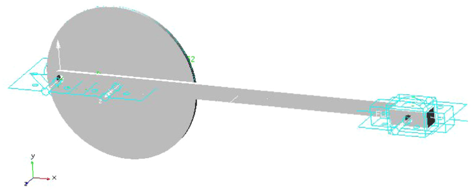
As shown in Figure 3, the crank-slider mechanism includes a crank, a connecting rod, and a slider. When establishing a dynamic model in Adams, it is necessary to add kinematic pairs and drives to the motion structure to realize the movement between various components. Rotational pairs are added between the crank and the ground, between the crank and the connecting rod, and between the connecting rod and the slider in the crank-slider mechanism model in sequence, and a sliding pair is added between the slider and the ground. In addition, a driving force is added to the rotational pair between the crank and the ground. The dynamic model after adding kinematic pairs and driving force is shown in Figure 4.

3D model of crank-slider mechanism.
Constraints and drives of crank-slider mechanism.
Visualization model of crank-slider mechanism
The design and development of the virtual scene is an important part of the digital twin visualization simulation. The virtual scene can create a highly realistic and reliable 3D virtual world according to requirements. In this simulation example, the 3D model of the crank-slider mechanism is imported into 3DMax software, converted into fbx format, and then imported into Unity3D. The imported virtual scene is shown in Figure 5. At the same time, a UI interface is made to realize the selection of the crank rotation drive proportional coefficient (Figure 6).

Virtual scene of crank-slider mechanism in Unity3D.

UI Interface.
Communication between UNITY 3D and multi-source heterogeneous dynamic models
So far, the virtual scene of the crank-slider mechanism has been built, but relying solely on the above virtual scene cannot realize the real-time dynamic simulation of the digital twin. It is also necessary to build the communication between Unity3D and Adams to realize real-time data interaction.
In ADAMS, six groups of system variables are added. The crank z-direction rotation angle, connecting rod z-direction rotation angle, connecting rod z-direction rotation angle, x and y direction displacements, and slider x-direction displacement are taken as output variables, and the crank rotation drive is taken as input variable. The drive is shown in the formula.

So far, the dynamic model in Adams has been established. In the Adams\Controls module, the FMU model conforming to the FMI standard of the crank-slider mechanism dynamic model is output through the plant export function. The FMU generation module is shown in Figure 7.
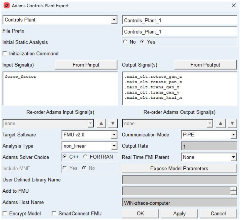
FMU generation module.
The data communication between the Adams FMU and the Unity3D scene system is the key to realizing virtual interaction, and also the key to the success of the digital twin dynamic system simulation based on Multi-source Heterogeneous Models. In Unity3D, a script is written in C# language to receive the position and attitude angle information of the crank-slider mechanism sent by the Adams FMU end, send the drive parameters of the crank-slider mechanism to the Adams FMU end, and associate the script with the crank-slider mechanism in the virtual scene.
The Adams FMU end receives the drive parameters of the crank-slider mechanism sent by the Unity3D end, performs dynamic calculation on the basis of the previous time step, and sends the position and attitude angle information of the crank-slider mechanism to the Unity3D end after the calculation is completed.
To make the objects in the simulation environment produce model movement behavior during operation, it is necessary to write corresponding behavior scripts and mount them to the corresponding model components for operation.
Taking the script that drives the model movement as an example, this script needs to receive the new coordinates of the model in the script from the FMU at a certain frequency, and continuously modify the old coordinate values of the object itself to the new coordinate values, thereby converting into the translation and rotation of the 3D model. The working principle of the model movement script is shown in Figure 8. The function of this script is to receive the coordinate and attitude angle data of the target model from the FMU in real time after the simulation starts, and modify the old coordinate and attitude angle data of the model itself to the new coordinate and attitude angle data.

Drive of visualization model of crank-slider mechanism.
Integration and verification of simulation system
After completing the modeling of the dynamic model and visualization model of the crank-slider mechanism, the two are connected in communication to form a co-simulation system. As mentioned earlier, Unity3D communicates by calling the dynamic model with the FMI standard interface generated by Adams.
Taking the crank rotation drive parameter force_factor = 1 as an example, the dynamic simulation system based on Multi-source Heterogeneous Models is simulated. The simulation results are shown in Figure 9.

Comparison Diagram of simulation and theoretical calculation results of dynamic simulation system.
Among them, the adams-fmi-unity calculation results curve is the slider displacement, and the theoretical calculation results is the theoretical calculation result of the slider displacement. The theoretical calculation formula is shown in equation (2),
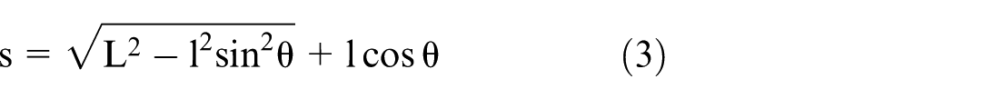
s is the slider displacement in mm; L is the connecting rod length in mm; l is the crank length in mm;
It can be seen from Figure 10 that the simulation results of the dynamic simulation system based on Multi-source Heterogeneous Models are consistent with the theoretical calculation results, and the simulation result error is less than 0.2%. The simulation results of the dynamic simulation system based on Multi-source Heterogeneous Models can be used for dynamic simulation in digital twin.

Error diagram of simulation and theoretical calculation results of dynamic simulation system.
Statistical evaluation of simulation accuracy
To provide a comprehensive assessment of simulation accuracy, multiple statistical metrics are employed (Table 1):
Statistical error metrics for simulation validation.

The RMSE of 0.0015 m should be interpreted relative to the mechanism’s operating range of approximately 0.26 m (from minimum to maximum slider displacement), representing a normalized error of 0.58%. This level of accuracy is sufficient for most engineering applications.
The error sources contributing to the observed deviation from theoretical values include:
Numerical integration: The Adams solver employs numerical integration with finite step size and tolerance, introducing discretization errors;
Interpolation: Data exchange between Adams and Unity occurs at discrete time points, requiring interpolation for intermediate visualization frames;
Floating-point arithmetic: The finite precision of floating-point representations introduces rounding errors;
Model idealization: The theoretical equations assume ideal rigid bodies and perfect joints, while the Adams model includes numerical regularization for solver stability.
The consistency of error metrics across multiple simulation runs (coefficient of variation less than 5%) confirms the repeatability of results and absence of systematic drift or instability.
On the basis of verifying the correctness of the simulation of the dynamic simulation system based on Multi-source Heterogeneous Models, the crank rotation drive parameter force_factor is modified to 2, 3, 4, and 5 respectively. The simulation results are shown in Figure 11.
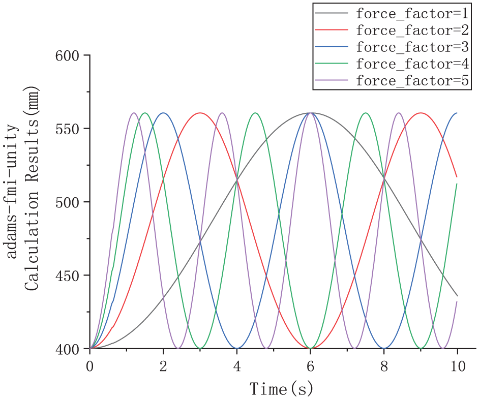
Interactivity simulation results of dynamic simulation system.
It can be seen from Figure 11 that the motion frequency of the slider displacement curve increases proportionally with the increase of the crank rotation drive parameter, indicating that modifying the crank rotation drive parameter can dynamically perform multi-source heterogeneous dynamic model simulation analysis, meeting the interactivity requirements of digital twin.
Discussion
Achievement of research objectives
The experimental results demonstrate that the proposed Adams-FMI-Unity co-simulation architecture successfully addresses the key challenges identified for customized production scenarios:
Cross-platform integration: The FMI 2.0 standard effectively bridges the gap between Adams multi-body dynamics simulation and Unity 3D visualization. The standardized interface abstracts the implementation details of each platform, enabling seamless data exchange without requiring detailed knowledge of internal data structures or solver algorithms.
Real-time performance: The master-slave time synchronization mechanism with 0.02-s communication step achieves smooth visualization at 50 frames per second while maintaining accurate simulation results. The measured communication latency of approximately 2 ms leaves substantial margin within the 20 ms step interval.
Visualization quality: The Unity 3D visualization provides intuitive representation of the mechanism motion, enabling operators to observe dynamic behavior that would be difficult to perceive from numerical data alone.
Comparison with related work
The proposed architecture offers several advantages compared to existing approaches:
Compared to proprietary integrated solutions, the FMI-based approach provides greater flexibility and openness, enabling integration of best-in-class tools from different vendors without vendor lock-in.
Compared to custom point-to-point integrations, the standardized FMI interface reduces development effort and improves maintainability. The FMI standard is maintained by an industry consortium, ensuring long-term support and compatibility.
Compared to offline simulation approaches, the real-time architecture enables interactive exploration and parameter adjustment that supports agile decision-making in customized production contexts.
Industrial challenges and limitations
The current implementation has limitations that should be addressed for production industrial deployment:
Data integrity: The system currently assumes that data transmitted between components is accurate and uncorrupted. In industrial environments with electromagnetic interference or network congestion, additional measures such as checksums, redundancy, and validation checks would be required.
Synchronization reliability: Network disruptions could cause missed synchronization points. Implementing comprehensive timeout handling, state recovery, and graceful degradation mechanisms would improve reliability.
Cybersecurity: Industrial digital twins may be targets for cyberattacks. The current implementation does not include authentication, encryption, or access control mechanisms essential for industrial deployment.
Scalability: The single-mechanism case study demonstrates basic functionality but does not fully validate the system’s ability to handle large-scale industrial systems with numerous components and multiple concurrent FMUs.
Framework generality and extensibility
The architecture is designed with generality in mind:
Model independence: The FMI standard supports arbitrary dynamic systems, not limited to mechanical mechanisms. Any system modelable in Adams or other FMI-compatible tools can be integrated.
Scalable integration: The co-simulation master can coordinate multiple FMUs, enabling simulation of complex multi-domain systems (mechanical, electrical, thermal, hydraulic).
Configurable visualization: The Unity visualization layer can be adapted to different systems by creating appropriate geometric models and configuring data bindings.
To fully validate framework generality, additional case studies with more complex systems are considered as future work, like multi-degree-of-freedom robotic manipulators.
Summary and outlook
Focusing on the demand for multi-source heterogeneous digital twin modeling of complex engineering systems in customized production under the background of Industry 4.0 and the emerging Industry 5.0 paradigm, and aiming at the technical limitations of traditional dynamic simulation tools, this study proposes and implements an Adams-FMI-Unity co-simulation technical scheme. The main contributions of this work are:
Based on the technical foundation of this research, future in-depth exploration can be carried out in the following directions:
Footnotes
Handling Editor: Aarthy Esakkiappan
Funding
The author received no financial support for the research, authorship, and/or publication of this article.
Declaration of conflicting interests
The author declared no potential conflicts of interest with respect to the research, authorship, and/or publication of this article.