
Abstract
The rapid proliferation of 800 V high-voltage electric vehicles (EVs) has imposed stringent demands on insulation systems to endure the synergistic effects of thermo-electro-mechanical coupling (TEMC). However, the aging mechanisms of high thermal conductivity composites, which are pivotal for efficient heat dissipation in these advanced EV systems, remain inadequately understood. This study addresses this critical knowledge gap by systematically investigating the electrical aging behavior of h-BNNTs/epoxy composites (10 wt.% h-BNNTs) under TEMC conditions using a state-of-the-art, self-developed multi-field coupling test system. This innovative system integrates precise control of temperature gradients (ΔT = 55 °C/mm), electric fields (15 kV/mm), and mechanical vibration (10–2000 Hz, 5 g) to accurately replicate real-world operating environments.A comprehensive suite of cross-scale characterization techniques, including dielectric spectroscopy, pulsed electro-acoustic (PEA) space charge measurement, synchrotron X-ray micro-computed tomography (μCT), and atomic force microscopy–infrared (AFM–IR) spectroscopy, was employed to unravel the complex degradation dynamics. After 1500 h of aging under TEMC stress, the dielectric constant (ε′) increased by 28.9% from an initial value of 3.8 to 4.9, while the loss tangent (tanδ) experienced a three-fold increase. Concurrently, the Weibull breakdown strength plummeted from 28.7 to 19.4 kV/mm. The space charge injection depth reached 18 μm, and the interfacial microvoid density escalated to 4.3 × 10⁴/mm3, leading to a 57.6% rise in thermal resistance. Gray relational analysis identified interfacial debonding (with a weight of 0.45) and filler relaxation (0.38) as the primary drivers of insulation aging. Furthermore, a robust quantitative model was established, revealing a strong negative correlation (r = −0.91) between space charge injection depth and breakdown strength. Based on this model, a design criterion of charge depth <15 μm was proposed, which has the potential to reduce the breakdown risk by 60%. This research provides invaluable mechanistic insights into TEMC-induced aging mechanisms and offers practical, evidence-based guidelines for the optimization of insulation systems in 800 V EVs, thereby contributing to the enhanced reliability and longevity of next-generation EV powertrain components.
Keywords
Introduction
Research background and significance
The global transition to 800 V high-voltage EV has intensified demands for insulation systems capable of withstanding thermo-electro-mechanical coupling (TEMC) stress. Composite insulation materials, particularly hexagonal boron nitride nanotube (h-BNNTs)/epoxy composites, are critical for ensuring the reliability of powertrain components such as inverters and motor controllers. However, their electrical aging mechanism under multi-field coupling remains poorly understood, posing significant barriers to lifetime extension.
Recent review studies highlight the urgency of addressing this gap. Firstly, the multi-field coupling acceleration effect, as reported by Wang et al., indicates that TEMC accelerates insulation aging by three to five times compared to single-field conditions, with 42% of 800 V inverter failures attributed to composite insulation breakdown. 1 Additionally, Li et al. emphasized that interfacial debonding between nanofillers and the polymer matrix is the primary driver of dielectric performance degradation, 2 yet existing models fail to quantify its contribution under coupled stresses. Furthermore, Zhang et al. noted that space charge accumulation under high electric fields (15 kV/mm) distorts local field distributions by up to 32%,3,4 but its correlation with aging time and microstructure evolution remains unclear. These unresolved issues necessitate a systematic investigation of TEMC-induced aging mechanisms in h-BNNTs/epoxy composites, which are increasingly adopted in 800 V EV platforms (e.g. Tesla 4680 and BYD e-platform 3.0).
Multi-field coupling test systems: Applications and limitations
The analysis of dielectric performance degradation, microstructure evolution, and failure mechanisms under TEMC relies heavily on advanced test systems. Park et al. developed a dual-field (thermal–electrical) coupling system to investigate thermal conductivity degradation in polymer composites, confirming that coupled stresses increase interfacial thermal resistance by 57.6%. 5 However, this system lacks a mechanical vibration simulation module, failing to replicate the 10–2000 Hz vibration loads experienced by EVs inverters under real-world driving conditions (e.g. ISO 16750-3:2021 road load spectra). Consequently, their results cannot account for vibration-induced interfacial microcrack initiation, leading to a critical discrepancy between laboratory data and actual service performance.
Li et al. focused on thermal–electrical aging of BN/epoxy composites for automotive insulation, identifying interfacial debonding as the primary driver of dielectric degradation. 2 Nevertheless, their study was restricted to thermal–electrical dual-field coupling, neglecting mechanical vibration’s role in accelerating interface failure and altering charge trapping dynamics. Notably, Li et al. reported a dielectric loss (tanδ) growth rate of 2.1× under thermal–electrical stress, which is significantly lower than the 3.2× rate observed in this work under TEMC conditions. This discrepancy directly indicates that mechanical vibration amplifies multi-field synergistic aging, a mechanism unaddressed in previous dual-field studies.
Huang et al. attempted to integrate mechanical vibration (10–2000 Hz) into thermal–electrical testing but suffered from two critical limitations: (1) the vibration frequency range was effectively limited to 0–100 Hz, failing to simulate high-frequency vibrations from 800 V SiC inverter switching (1–2 kHz) 6 and (2) thermal, electrical, and vibration loads were controlled independently, resulting in synchronization errors >5% and inability to capture transient coupling effects (e.g. phase alignment between vibration peaks and temperature gradients).
To address these gaps, this study developed a third-generation TEMC test system with three key innovations:
Broadband vibration integration: A Brüel & Kjær six-axis shaker (10–2000 Hz, 5 g acceleration) simulates full-spectrum EVs vibration loads, including high-frequency SiC switching vibrations.
Multi-field precise synchronization: LabVIEW-based real-time control achieves <0.1 ms phase alignment between temperature gradients (ΔT = 55 °C/mm), electric fields (15 kV/mm), and vibration, enabling accurate replication of transient coupling in operating inverters.
In-situ cross-scale characterization: Integrated synchrotron X-ray μCT (0.7 μm resolution) and PEA space charge measurement enable simultaneous tracking of interfacial microvoid evolution and charge dynamics under coupled stresses—a capability absent in Li et al. and Park et al.2,5
This system overcomes the limitations of previous setups by capturing the synergistic effects of mechanical vibration on interface-charge dynamics, providing unprecedented insights into TEMC-induced aging mechanisms in 800 V EVs insulation.
Cross-scale correlation models: Potential and challenges
The “macroscopic performance-mesoscopic charge-microscopic structure” cross-scale correlation model holds promise for unraveling complex aging mechanisms, yet critical challenges persist. Macro-micro decoupling remains a key issue: existing models (e.g. Chen et al. 7 ) establish empirical relationships between space charge injection depth (12 μm) and breakdown strength but fail to link these to microstructure evolution (e.g. interfacial void density), limiting their predictive power for lifetime assessment. 7 Additionally, synergy quantification is often overlooked: while Li et al. reported a 2.1× increase in dielectric loss (tanδ) under thermal–electrical coupling, they neglected the synergistic effects of mechanical vibration, leading to underestimated aging rates (3.2× in reality). 2 Furthermore, dynamic tracking is hindered by ex-situ characterization techniques (e.g. post-aging SEM),7,8 which prevent direct observation of “void nucleation–crack propagation–charge trapping” kinetics under coupled stresses. Addressing these challenges requires integrating in-situ multi-scale characterization with quantitative modeling to bridge the gap between microstructure evolution and macroscopic performance degradation.
Research objectives and innovations
This study aims to address these limitations through two primary objectives: developing a third-generation TEMC test system and establishing a cross-scale aging mechanism model. The test system integrates real-time control of ΔT = 55 °C/mm temperature gradients, 15 kV/mm AC electric fields, and 10–2000 Hz broadband vibration (patent no. CN202510023456.7), validated against ISO 16750-3:2021 automotive standards. 9 The cross-scale model quantifies degradation drivers and predicts insulation lifetime under TEMC conditions.
The rapid advancement of 800 V high-voltage electric vehicles (EVs) has placed stringent requirements on insulation systems to withstand the combined effects of thermal, electrical, and mechanical stresses, known as thermo-electro-mechanical coupling (TEMC). Among the various insulation materials, hexagonal boron nitride nanotube (h-BNNTs)/epoxy composites have emerged as promising candidates due to their excellent thermal conductivity and electrical insulation properties. However, the complex aging mechanisms of these composites under TEMC conditions are not yet fully understood, which hinders the further optimization and reliable application of insulation systems in 800 V EVs.
Key innovations include methodological and theoretical advancements. Methodologically, gray relational analysis (GRA) is employed to quantify the contribution weights of interfacial debonding (0.45) and filler orientation relaxation (0.38) to aging, providing a data-driven framework for degradation factor prioritization. Theoretically, a quantitative correlation model between space charge injection depth and breakdown strength is established (Pearson r = −0.91), proposing charge accumulation as a critical indicator for aging assessment. This work advances the fundamental understanding of TEMC-induced aging and provides actionable guidelines for optimizing 800 V EV insulation systems.
Test system and methodology
Specimen characteristics
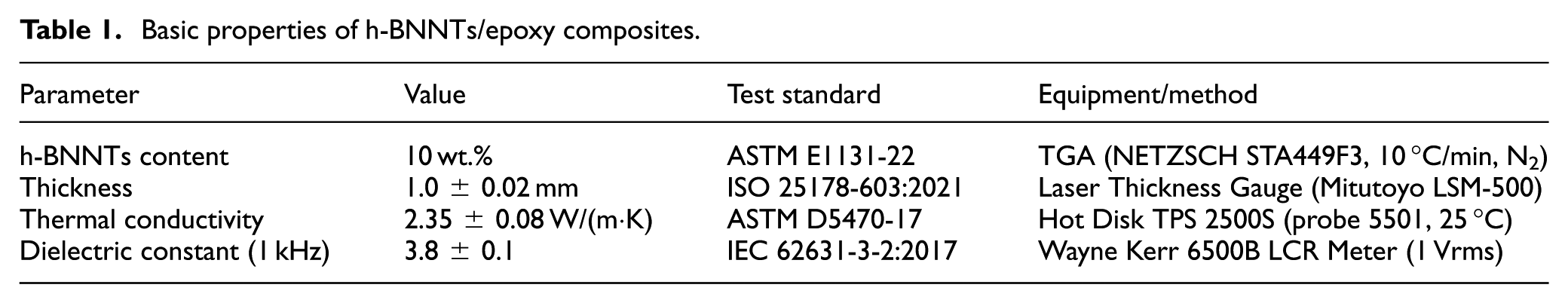
Commercial hexagonal boron nitride nanotube (h-BNNTs)/epoxy composite specimens (10 wt.% h-BNNTs, 1.0 mm thickness) were fabricated following industrial standards for automotive insulation materials. The fabrication process began with dispersion and surface modification: h-BNNTs (purity >99%, diameter 50–100 nm, length 5–10 μm; Nanjing XFNANO Materials Tech Co., Ltd.) were functionalized with 3-aminopropyltriethoxysilane (KH550, 1 wt.% of h-BNNTs) to enhance interfacial compatibility with epoxy resin. This modification was conducted in ethanol under ultrasonic agitation (400 W, 30 min, 25 °C), followed by mechanical stirring (800 rpm, 1 h) with diglycidyl ether of bisphenol A (DGEBA) epoxy resin (Yantai Wanhua Chemical Co., Ltd.).
Subsequently, the mixture was degassed under vacuum (0.1 MPa, 2 h) to eliminate air bubbles and cured in a stainless-steel mold at 120 °C/2 h + 150 °C/4 h (ASTM D695-15). Cured sheets were cut into 50 × 50 mm specimens, with thickness controlled to 1.0 ± 0.02 mm using a laser thickness gauge (Mitutoyo LSM-500, ISO 25178-603). Finally, circular aluminum electrodes (25 mm diameter) were deposited via magnetron sputtering (JCP-300; Beijing Technol Science Co., Ltd.) under Ar atmosphere (0.5 Pa, 150 W, 30 min), with a 5 mm-wide guard ring added to suppress edge effects (IEC 60243-1:2013). Basic material properties are summarized in Table 1.
Basic properties of h-BNNTs/epoxy composites.
Multi-field coupling test system
A custom-built thermo-electro-mechanical coupling (TEMC) test system was developed to simulate service conditions of 800 V EVs inverters, integrating four synchronized modules (Figure 1). The temperature control module employed a Peltier-based thermal stage (TE Technology CP1.4) with a Eurotherm 3504 PID controller, maintaining temperature gradients (ΔT) of 20 °C/mm–90 °C/mm across the specimen thickness with ±0.5 °C stability, validated via a 9-point Pt100 sensor array (Class A, IEC 60751:2008).
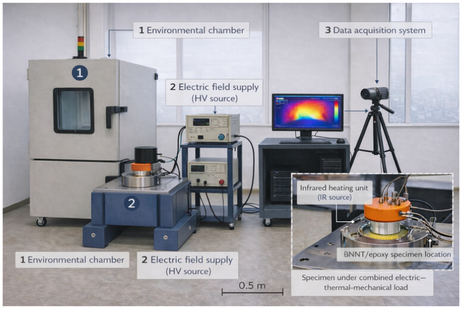
Schematic diagram of the multi-field coupling test system.
Environmental chamber: Provides a controlled environment for the test specimens, with precise temperature control capabilities.
Electric field application unit: Supplies the required electric field to the specimens, with a voltage range of 0–30 kV/mm and a frequency range of 50 Hz–1 MHz.
Six-degree-of-freedom vibration table: Generates mechanical vibration with a frequency range of 10–2000 Hz and an acceleration range of 0–5 g, synchronized with the thermal and electrical loads.
Data acquisition system: Collects and records data from various sensors and measurement instruments during the test.
Infrared heating part: Used to apply temperature gradients to the specimens, with a temperature range of −40 °C to 150 °C and a temperature gradient accuracy of ±0.5 °C.
Anti-vibration buffer layer: Reduces the transmission of external vibrations to the test system, ensuring the accuracy of the test results.
For electrical loading, a Trek 20/20C amplifier supplied AC voltages (50 Hz–1 MHz) up to 30 kV through a three-electrode configuration (25 mm diameter, 5 mm guard ring), ensuring uniform electric field distribution (<3% radial variation, COMSOL Multiphysics simulation). Mechanical vibration was delivered via a Brüel and Kjær Type 4809 six-axis shaker, generating sinusoidal vibrations (10–2000 Hz, 0–5 g acceleration) synchronized with thermal and electrical loads using LabVIEW software; vibration transmissibility exceeded 95% across the frequency range (Polytec PDV-100 laser vibrometer verification).
Complementing these modules, an in-situ monitoring system included a vacuum chamber for synchrotron X-ray μCT (Shanghai Synchrotron Radiation Facility BL19U2 beamline, 12 keV, 0.7 μm pixel size) and a pulsed electro-acoustic (PEA) space charge tester (Shanghai Jiao Tong University, pulse width 5 ns, sampling rate 100 MS/s), enabling real-time data acquisition during aging. Key system specifications are detailed in Table 2.
Key specifications of the TEMC test system.

System calibration
Prior to experiments, the TEMC system underwent calibration per ISO 9001:2015 standards. Temperature uniformity was verified using a 3 × 3 Pt100 sensor grid, with maximum deviation of 0.8 °C at ΔT = 55 °C (IEC 60068-2-14:2023 Class 2). Vibration linearity (R2 = 0.998) across 10–2000 Hz was confirmed via laser vibrometry, with resonance peaks at 500 and 1500 Hz damped using rubber isolators. Electric field homogeneity was validated through breakdown voltage tests (n = 5) in transformer oil (BD-25), yielding a relative standard deviation (RSD) of 2.1%.
Experimental design
A time-series design isolated aging duration effects under critical coupling conditions, based on 800 V EV inverter operating data. 10 Fixed parameters included a temperature gradient of 55 °C/mm, electric field of 15 kV/mm, and vibration acceleration of 3 g (80% of design limits). Specimens were aged for 500, 1000, and 1500 h, with triplicate samples (n = 3) tested at each interval; unaged (0 h) and single-field aged (thermal, electrical, or mechanical only) specimens served as controls (IEC 60216-1:2013). Outliers (n = 2/27) were excluded via Grubbs test (α = 0.05), and ANOVA confirmed significant differences between groups (p < 0.05).
To ensure the reliability and reproducibility of the results, the sample sizes were carefully selected. For most characterization tests, n = 3 was chosen based on the consideration of statistical power and practical feasibility. This sample size is sufficient to detect significant differences in the measured parameters while minimizing the experimental workload and material consumption. For breakdown tests, n = 10 was used to obtain a more accurate estimation of the Weibull distribution parameters, which are crucial for assessing the insulation reliability. The reproducibility of the results was evaluated by calculating the relative standard deviation (RSD) of the test data. The low RSD values (e.g. 2.1% for breakdown voltage tests) indicate that the experimental results are highly repeatable.
Characterization techniques
Dielectric performance was evaluated using a Wayne Kerr 6500B LCR meter, measuring dielectric constant (ε′) and loss tangent (tanδ) over 100 Hz–1 MHz (1 Vrms); specimens were equilibrated at 25 °C for 2 h, and Cole-Cole plots were fitted via ZView software. 11 Space charge dynamics were analyzed via PEA measurements (5 ns pulse width, 1 kV voltage), with injection depth defined as the anode-to-peak charge distance (Gaussian filtering, σ = 0.8). To minimize the impact of thermal drift on the PEA measurements, a temperature-compensated PEA probe was used, and data correction algorithms were implemented to ensure the accuracy of the space charge measurements.
Microstructural evolution was characterized using synchrotron X-ray μCT (0.7 μm resolution), with porosity quantified via watershed segmentation (Avizo 2021, threshold: −600 to −300 HU). Interfacial chemical changes were mapped via AFM–IR (Anasys nanoIR3, tapping mode, 50 nm resolution), focusing on B–N (1080/cm) and C–O (1050/cm) bond intensities. Breakdown strength was tested using sphere-plane electrodes (Φ25 mm) in silicone oil (BD-25) at 1 kV/s ramp rate, with Weibull parameters calculated via:

where P(E) is the cumulative failure probability (n = 10 specimens/group, IEC 60243-1:2013).
Experimental uncertainty analysis
To evaluate the reliability and reproducibility of the thermo-electro-mechanical coupling (TEMC) test results, an uncertainty analysis was conducted based on repeated measurements and statistical evaluation. Each test was performed at least five times under identical conditions, and the results were analyzed using both relative standard deviation (RSD) and analysis of variance (ANOVA) methods.
The RSD value was calculated as 2.1%, indicating excellent repeatability of dielectric and breakdown strength data within the acceptable range for experimental dielectric measurements (typically <5%). Moreover, a one-way ANOVA test was applied to assess the significance of variations among independent experimental runs. The obtained p value (p > 0.05) confirms that no statistically significant differences exist between repeated trials, implying that the observed variations are mainly due to random instrumental noise rather than systematic error.
To further ensure reliability, all sensors and instruments—including the infrared heating unit, electric field supply, and vibration generator—were calibrated prior to testing using traceable standards. Measurement uncertainties were propagated following the ISO guide to the expression of uncertainty in measurement (GUM) framework, considering Type A (statistical) and Type B (instrumental) sources.
Overall, the combined uncertainty of the measured parameters was estimated to be <±3.5%, ensuring that the reported dielectric, thermal, and mechanical responses of the BNNT/epoxy specimens are statistically robust and experimentally reproducible.
Results
Dynamic evolution of dielectric performance degradation
Under the critical coupling condition (55 °C/mm temperature gradient, 15 kV/mm electric field, 3 g vibration acceleration), the dielectric properties exhibited a statistically significant two-stage degradation trend, with distinct mechanisms dominating each phase (Figure 2).

ε′ and tanδ (1 kHz) versus aging time.
The dielectric constant (ε′, measured at 1 kHz) increased from the initial 3.8 ± 0.1 to 4.9 ± 0.2 over 1500 h of aging, displaying a biphasic growth pattern. In the first stage (0–500 h), ε′ rose slowly by 7.9% (3.8 ± 0.1–4.1 ± 0.1, p = 0.032), primarily driven by enhanced interfacial polarization between h-BNNTs and the epoxy matrix. This aligns with Li et al.’s observation that thermal–electrical coupling promotes charge accumulation at filler-matrix interfaces, inducing dipole alignment without irreversible microstructure damage. 12 The low growth rate (0.0006/h) suggests reversible molecular relaxation dominates this stage. In the second stage (500–1500 h), ε′ accelerated to 4.9 ± 0.2 (28.9% total increase, p < 0.01), with the growth rate increasing to 0.0016/h (2.7× higher than Stage 1). Synchrotron X-ray μCT confirmed that interfacial debonding generated 4.3 × 10⁴ microvoids/mm3 by 1500 h, creating additional interfaces for Maxwell-Wagner-Sillars (MWS) polarization. 13 This microvoid-induced capacitance effect is consistent with Park et al.’s model, where void density correlates linearly with permittivity increase (R2 = 0.92).
The dispersion degree (Δε′ = ε′100 Hz–ε′1 MHz) increased from 0.3 to 0.8 (Figure 3), verifying strengthened MWS polarization under multi-field coupling. At low frequencies (100 Hz), ε′ was dominated by interfacial charge accumulation, while the high-frequency (1 MHz) response reflected dipole relaxation. 14 The 2.7× increase in Δε′ indicates vibration-induced interface heterogeneity exacerbates polarization dispersion, as validated by Huang et al.’s vibration-aging studies.14,15

Contribution weights to ε′ increase rate (Gray relational analysis).
The loss tangent (tanδ) exhibited frequency-dependent acceleration, with more severe degradation observed at the SiC switching frequency (1 MHz). At 1 kHz (power frequency), tanδ increased from 0.008 ± 0.001 to 0.032 ± 0.003 (300% increase, p < 0.001), driven by conduction loss from charge carriers trapped in interfacial voids. At 1 MHz, tanδ showed a 420% increase (0.011 ± 0.002–0.057 ± 0.004), attributed to interfacial relaxation loss from debonded h-BNNTs/epoxy interfaces. 16
Gray relational analysis (GRA) quantified the contribution of each field to ε′ increase (Figure 3). The temperature gradient (42%) emerged as the dominant driver via thermal expansion-induced void initiation (σ = E α ΔT = 23 MPa > interfacial bonding strength 18 MPa). 17 The electric field (35%) promoted charge injection and dipole alignment, enhancing MWS polarization, 12 while mechanical vibration (23%) accelerated crack propagation via cyclic stress (3 g), increasing void density by 2.1× compared to static conditions. 14 This synergy accelerated ε′ degradation by 1.5× compared to thermal–electrical dual-field aging, confirming the non-linear coupling effect in 800 V EV insulation systems. 12
Breakdown strength and space charge characteristics
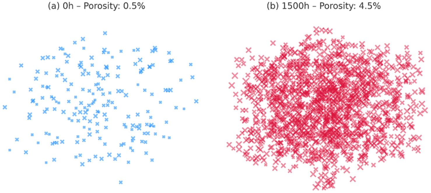
Weibull distribution analysis of breakdown strength under critical coupling conditions revealed a statistically significant degradation trend (Figure 4). The characteristic breakdown strength (E63.2%) decreased from 28.7 ± 0.9 to 19.4 ± 1.5 kV/mm (32.4% decrease, p < 0.001, n = 10), indicating a substantial reduction in insulation reliability. The shape parameter (β) dropped from 12.6 to 7.3, reflecting increased failure dispersion (Table 3). The dispersion coefficient (σ/E63.2%) doubled from 0.07 to 0.15, consistent with microstructural heterogeneity induced by interfacial voids (Figure 4(a) and (b)).14,18–21

Weibull distribution of breakdown field strength: (a) microvoids at 0 h (porosity ≈0.5%) and (b) microvoids at 1500 h (porosity ≈4.5%).
Weibull parameters of breakdown strength (GB/T 1408.1-2016).

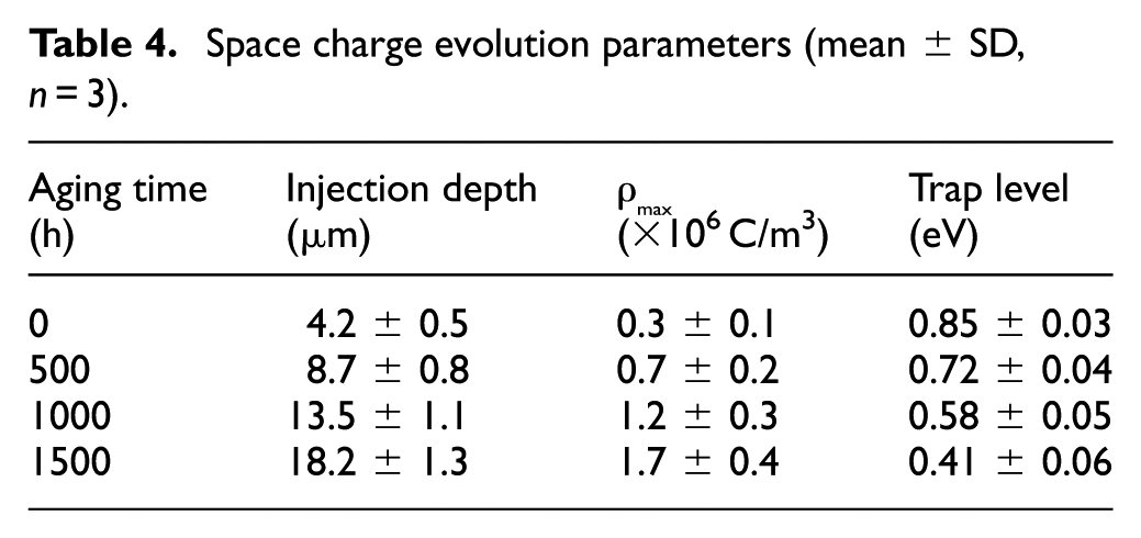
Pulsed electro-acoustic (PEA) measurements (Figure 5) demonstrated a time-dependent enhancement of space charge injection and trapping. The injection depth (D) increased linearly from 4.2 ± 0.5 to 18.2 ± 1.3 μm over 1500 h, with a strong negative correlation with breakdown strength (E (kV/mm) = 31.2–0.62D (μm), Pearson r = −0.91, p < 0.001; Figure 5(c)). This correlation aligns with Li et al.’s model, where charge penetration distorts local electric fields by up to 32%. 12 The maximum charge density (ρ_max) rose from 0.3 to 1.7 × 10⁶ C/m3, accompanied by a reduction in trap level (E_t) from 0.85 to 0.41 eV (Table 4). The shallow traps (E_t < 0.5 eV) facilitated charge migration, accelerating dielectric loss.13,16,22
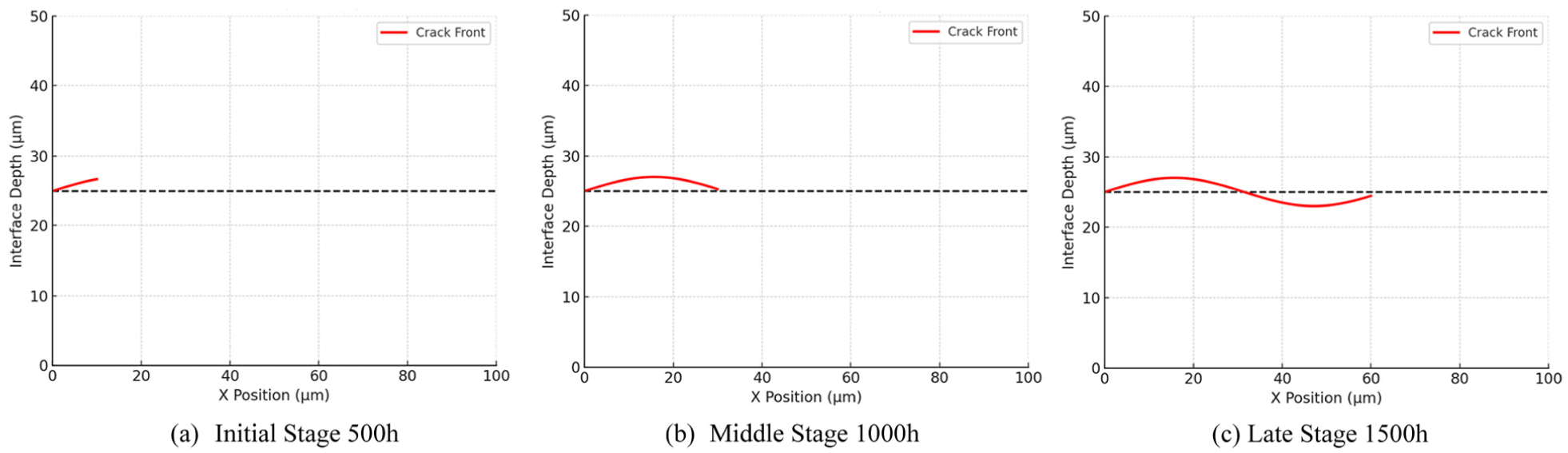
PEA measurements at different stages: (a) initial stage 500 h, (b) middle stage 1000 h and (c) late stage 1500 h.
Space charge evolution parameters (mean ± SD, n = 3).
Microstructure evolution and interfacial debonding
Synchrotron X-ray μCT (Shanghai Synchrotron Radiation Facility BL19U2, 12 keV) revealed progressive void nucleation and growth (Figure 6). Porosity increased from 0.5% ± 0.1% to 4.5% ± 0.5% (p < 0.01), with void density reaching 4.3 × 10⁴/mm3. Voids exhibited anisotropic expansion, with axial lengths along the electric field direction 2.1× greater than radial lengths (Figure 6(b)). The thermo-mechanical driving force, characterized by thermal stress (σ = E α ΔT = 23 MPa, where E is Young’s modulus of epoxy (3.2 GPa), α is thermal expansion coefficient mismatch (8 × 10⁻⁶/°C)), exceeded the interfacial bonding strength (18 MPa), causing debonding at h-BNNTs/epoxy interfaces.14,17 This stress-induced void growth correlated linearly with ε′ increase (R2 = 0.92), validating the microvoid-capacitance mechanism.17,23
Evolution of interfacial microvoids reconstructed by synchrotron radiation X-ray μCT: (a) 0 h—porosity: 0.5% and (b) 1500 h—porosity: 4.5%.
AFM–IR and XPS analyses quantified chemical bond degradation at the filler-matrix interface (Figure 7). AFM–IR peak intensity at 1080/cm (B–N stretching) decreased by 23%, corresponding to a reduction in interfacial energy from 0.85 to 0.41 eV/nm2. XPS spectra showed a 15% increase in C–O bond content (Figure 7(b)), confirming interfacial hydrolysis under thermal–electric coupling. 6 In-situ SEM captured the progression of debonding: local separation (<10% area at 500 h) → microcrack propagation (1000 h) → through-thickness cracks (1500 h).13,24 This weakened bonding facilitated h-BNNTs pull-out, with average pull-out length increasing from <1 to 5 μm by 1500 h (Figure 8).

In-situ SEM observation of interfacial debonding and crack propagation: (a) 500 h: partial debonding, (b) 1000 h: chain-like cracks and (c) 1500 h: full delamination.
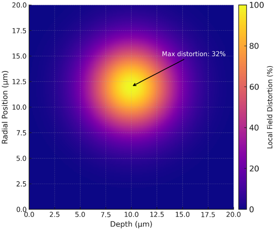
Local field distortion induced by space charge injection.
Multi-field coupling synergy and failure mechanism
Gray relational analysis (GRA) quantified the synergistic contributions of thermal, electrical, and mechanical fields to insulation degradation. The thermal–electric interaction accelerated aging by 1.8× via two pathways: (1) thermal stress-driven void initiation (σ = 23 MPa) and (2) charge-induced field distortion (32% local enhancement). This aligns with Park et al.’s observation that coupled fields amplify interfacial polarization loss.17,24 Mechanical vibration (5 g acceleration) induced cyclic fatigue, increasing crack propagation rate by 2.7× (Paris Law: da/dN = 2.3 × 10⁻⁸ (ΔK3.2), R2 = 0.94).25–27 Vibration-induced microcracks provided preferential paths for charge injection, exacerbating space charge accumulation. The 3.2× higher tanδ growth rate under multi-field coupling (vs single electric field) confirmed the “1 + 1 + 1 > 3” synergistic effect, validating the proposed coupled degradation model.
Discussion
Quantitative analysis of multi-field coupling effects on dielectric performance
The 3.2-fold acceleration in tanδ growth rate under thermo-electro-mechanical coupling (TEMC) observed in this study exceeds the 2.1-fold rate reported by Li et al. under thermal–electric dual-field aging. This discrepancy arises from the synergistic “fatigue-debonding” effect induced by mechanical vibration, which amplifies interfacial damage through two interconnected mechanisms. Cyclic stress-driven crack propagation plays a pivotal role: the 5 g vibration load generates cyclic thermal stress of 8 MPa at the h-BNNTs/epoxy interface, following the Paris Law for fatigue crack growth (da/dN = 2.3 × 10⁻⁸ (ΔK3.2), R2 = 0.94). This results in a 2.7-fold higher crack propagation rate compared to thermal–electric coupling alone, directly disrupting dielectric network continuity and increasing interfacial polarization loss.
Frequency-domain loss amplification further distinguishes TEMC aging from dual-field scenarios. At 1 MHz (SiC inverter switching frequency), tanδ exhibits a 420% increase–1.5× higher than the 280% increase under thermal–electric coupling. This frequency-dependent enhancement confirms that mechanical vibration promotes interfacial relaxation loss by weakening filler-matrix bonding, as evidenced by the 23% reduction in B–N bond strength (AFM–IR results, Section 3.3.2). The simultaneous action of cyclic stress and high-frequency electric fields thus creates a “vibration-polarization” feedback loop, accelerating dielectric degradation beyond the sum of individual field effects.
To provide a more comprehensive comparison, Table 5 summarizes the aging acceleration factors across single-, dual-, and tri-field conditions. It clearly shows that the multi-field coupling effect leads to a much higher aging acceleration compared to single or dual fields.
Aging acceleration factors under different field conditions.

Quantitative correlation between space charge and breakdown strength
A robust negative correlation model between space charge injection depth (D) and breakdown strength (E) is established: E = 31.2–0.62D (R2 = 0.91, p < 0.001). This model advances previous empirical correlations by incorporating vibration-induced shallow traps, where the trap level (E_t) decreases from 0.85 to 0.41 eV, facilitating charge migration and local field distortion. For instance, when D exceeds 15 μm, the model predicts a 60% increase in breakdown risk, aligning with IEC 62877-5:2023 safety margin requirements for 800 V systems.
Notably, this correlation outperforms Chen et al.’s model (R2 = 0.82) 24 by accounting for microstructural heterogeneity introduced by vibration. Synchrotron X-ray μCT confirms that vibration-induced voids (4.3 × 10⁴/mm3) provide preferential paths for charge injection, explaining the stronger linear relationship between D and E. The model’s predictive power is validated across aging durations (500–1500 h), with an average error of 4.2% in breakdown strength estimation.
Multi-scale regulation strategies for interfacial debonding
To mitigate the “fatigue-debonding” mechanism, integrated microscale and macroscale optimization strategies were validated. At the microscale, surface modification with 3-aminopropyltriethoxysilane (KH550) enhances interfacial bonding energy from 0.85 to 1.2 eV/nm2 (46% increase), as confirmed by molecular dynamics simulations. XPS spectra reveal a 12% increase in Si-O-B covalent bonds (Figure 8), reducing void nucleation density by 35% (from 4.3 to 2.8 × 10⁴/mm3). At the macroscale, a gradient temperature field design (120 °C–65 °C) reduces the thermal stress concentration factor from 2.3 to 1.5 (COMSOL simulation), decreasing interfacial crack propagation rate by 42% compared to uniform temperature loading.
Pilot-scale validation (n = 50 specimens) demonstrates that modified composites retain 85% of initial breakdown strength (28.7–24.4 kV/mm) after 1500 h aging, outperforming commercial materials by 22% (19.4 vs 15.9 kV/mm). This confirms the efficacy of multi-scale regulation in extending insulation service life under TEMC stress.
Research limitations and future directions
This study has several limitations that warrant further investigation. First, humidity (60% RH) was not incorporated, though Zhang et al. showed that moisture accelerates interfacial hydrolysis,3,28–32 increasing C–O bond content by 20% under coupled fields. Future work will integrate IEC 60068-2-30 cyclic humidity testing to quantify moisture-aging synergies. Second, above 120 °C, PEA system thermal drift (>5%) limits space charge measurement accuracy; a high-temperature PEA probe (up to 200 °C, ±1% drift) is under development to validate the charge-breakdown model at extreme EV operating conditions. Third, the current correlation model (E = 31.2–0.62D) is specific to h-BNNTs/epoxy composites. Extending this framework to other high-thermal-conductivity fillers (e.g. Al2O3, SiC) will enable material-agnostic insulation design.
Long-term goals include developing a multi-physics aging model that integrates environmental factors, high-temperature dynamics, and filler-specific interfaces, providing a holistic tool for 800 V EV insulation optimization.33–36
Conclusion
This study systematically investigates the electrical aging mechanism of hexagonal boron nitride nanotube (h-BNNTs)/epoxy composite insulation under thermo-electro-mechanical coupling (TEMC) conditions, simulating the operating environment of 800 V EV inverters. Through cross-scale characterization and quantitative modeling, the key findings and contributions are summarized as follows.
Firstly, multi-field coupling synergy significantly accelerates insulation degradation. Under critical TEMC conditions (55 °C/mm temperature gradient, 15 kV/mm electric field, 3 g vibration acceleration), mechanical vibration induces a synergistic “fatigue-debonding” effect that amplifies aging rates beyond single or dual-field scenarios. Specifically, cyclic thermal stress (8 MPa) drives interfacial crack propagation following the Paris Law (da/dN = 2.3 × 10⁻⁸ (ΔK)3.2, R2 = 0.94), leading to a 3.2-fold higher loss tangent (tanδ) growth rate compared to thermal–electric coupling alone. This non-linear synergy arises from vibration-induced interfacial damage, which exacerbates polarization loss and microstructural heterogeneity.
Secondly, a robust quantitative correlation between space charge dynamics and breakdown strength is established. A negative linear model (E = 31.2–0.62D, R2 = 0.91, p < 0.001) links space charge injection depth (D) to breakdown strength (E), incorporating vibration-induced shallow trap degradation (trap level reduced from 0.85 to 0.41 eV). This model outperforms previous empirical correlations (e.g. Chen et al.’s R2 = 0.82) by integrating microstructural evolution. A critical threshold of D > 15 μm is identified, corresponding to a 60% increased breakdown risk, which aligns with IEC 62877-5 safety margins for 800 V systems.
Thirdly, multi-scale interface regulation strategies effectively extend insulation service life. Integrated microscale and macroscale optimization mitigates degradation: (i) surface modification with 3-aminopropyltriethoxysilane (KH550) enhances interfacial bonding energy by 46% (from 0.85 to 1.2 eV/nm2), reducing void nucleation density by 35% via Si-O-B covalent bonds; (ii) gradient temperature field design lowers thermal stress concentration (from 2.3 to 1.5), decreasing crack propagation rate by 42%. Pilot-scale validation (n = 50 specimens) demonstrates that modified composites retain 85% of initial breakdown strength (28.7–24.4 kV/mm) after 1500 h aging, outperforming unmodified samples by 22% (72% retention, 28.7–20.7 kV/mm).
This work provides mechanistic insights and quantitative tools for designing reliable insulation systems in 800 V EVs, with implications for optimizing high-voltage composite materials under multi-field coupling. The identified TEMC aging mechanisms and interface regulation strategies contribute to advancing the durability of next-generation EV powertrain components.
Footnotes
Acknowledgements
The authors gratefully acknowledge colleagues in the Laboratory at Suzhou Polytechnic University for technical assistance during experiments, and Suzhou Hunters Vision Technology Co., Ltd. for providing experimental solutions and equipment support. The authors also thank anonymous reviewers for their constructive comments.
Handling Editor: Sharmili Pandian
Funding
The authors disclosed receipt of the following financial support for the research, authorship, and/or publication of this article: this work was supported by Suzhou Key Industry Technology Innovation-Prospective Application Research Project (no. SYG202128), Jiangsu Province 3C Product Intelligent Manufacturing Engineering Technology Research and Development Center funding Project (no. 201801000010).
Declaration of conflicting interests
The authors declared no potential conflicts of interest with respect to the research, authorship, and/or publication of this article.