
Abstract
To reduce the error sensitivity of cylindrical worm drive, the curve constructed worm drive is proposed. Depend on the theory of constructing tooth surfaces by the conjugate curve, the meshing theory, and mathematical model of the curve constructed worm drive are built. The tooth contact analysis of curve constructed worm drive is proposed, and it is simulated by the numerical method and finite element method. The meshing characteristic of two-point contact is verified, and the sensitivity is examined in terms of center distance, shaft angle, and axial errors, as well as the finite element analysis is utilized to examine the tooth contact in the presence of errors. The analyzed results show that this novel worm drive has well adaptation to the errors. This study is intended to provide a new way forward in the design of point contact worm drive.
Introduction
The cylindrical worm transmission is a type of spatially staggered shaft transmission device that offers numerous advantages, including a large transmission ratio, compact structure, and smooth operation. As such, it finds widespread use across various industries. 1 When designing a cylindrical worm drive, it is typically expected to have a linear contact between the cylindrical worm and the worm gear. However, achieving linear contact in the meshing process is challenging due to manufacturing and mounting errors. Because the line contact in conventional worm gear pairs is a theoretically fragile state of perfection, it is highly sensitive to both manufacturing and alignment errors. The presence of such errors causes the theoretically infinite contact line to degenerate into one or several isolated contact points and edge contacts. This shift in load-bearing behavior leads to an exponential increase in localized contact stress, which can easily trigger early-stage pitting, scuffing, and wear. In contrast, the point contact area, after running-in, forms a small elliptical patch in practical engineering applications. When errors such as center distance deviation, shaft angle misalignment, or manufacturing inaccuracies occur, this contact area can freely shift and adjust its shape on the tooth surface, thereby avoiding edge contact and stress concentration. Thus, the conventional worm gear pair evolves from a theoretically ideal line contact—representing a brittle optimum—into a point contact in engineering practice, exemplifying a robust sub-optimum. Hence, the substitution of a linear contact with a point contact can effectively reduce the sensitivity to errors in the worm drive.2–5
Regarding point-contact tooth meshing, some studies have been finished by researchers. Seol2,3 investigated the effects of contact shift and transmission errors on line-contact worm gears. The transfer point for the linear contact has been determined and computerized simulations have been developed. Litvin and Donno 4 and Litvin et al. 5 proposed a worm gear transmission that features localized contact for load bearing. Moreover, the influence of misalignment was investigated by TCA computer program. Litvin et al. 6 also proposed design of involute crossed helical gears. Litvin et al. 7 and Gonzalez-Perez et al. 8 proposed a novel geometry for worm gearing that effectively reduces the sensitivity of the gearing to error. Application of TCA confirms the reduced sensitivity to deviation and improved meshing conditions of this worm gearing. Shi et al. 9 investigated the effect of errors on the contact area and improved the engagement performance by localizing the contact zone to reduce the sensitivity to the loads and the errors. Simon10,11 suggested the utilization of an oversized hob for machining the worm wheel. Aiming to diminish the sensitivity to errors and the mismatch contact of the worm transmission. And computer aided contact analysis of load-bearing tooth flanks completed. Dudás 12 has proposed a novel type of worm gearing characterized by continuous pointwise meshing. Its main advantage is the lack of transmission errors and its ability to tolerate misalignments well. Meng et al.13,14 investigated the mismatched meshing of conical surface enveloping worm gear and the mismatched meshing of ZC1 worm gear. The two worm drive pairs not only have good meshing performance, but also are insensitive to assembly errors. Zhao et al 15 investigated the meshing theory of nonspecific mismatched transmission on the example of a type of mismatch transmission. Chi et al. 16 analyzed an hourglass worm transmission constituted by a hourglass worm and a modified worm gear. The study rescues the surface that this worm gearing is capable of achieving ideal point contact and is insensitive to positioning errors. Chen et al. 17 proposed a design for a multitooth point contact hourglass worm transmission. This hourglass worm gear transmission can grind precisely. Ye et al. 18 studied a novel point contact double lead worm gear. The ability of the hourglass worm to realize backlash-adjustable is confirmed by TCA and finite element simulation. Zheng et al. 19 offered a novel hourglass worm drive with point contact. The contact performance and backlash-adjustable capability of this hourglass worm gearing are verified by computer simulation and prototype experiments. Li et al. 20 proposed a novel point-contact hourglass worm gear based on modified involutes by modifying the involute gears. The analysis of meshing performance and error adaptation is completed. Ye et al. 21 studied a mismatched TI worm gearing. The contact characteristics of the worm gear can be affected by adjusting the parameters of the intermediate gear. This mismatched TI worm gearing performs well in terms of load carrying capacity and error adaptation has been verified. Ren22,23 presented a point contact worm transmission constructed from two generating surfaces. Additionally, A method is further proposed for the generation of point-contact worm drive using two conjugate involute helical surfaces. The aforementioned point contact transmissions primarily consist of mismatched engagements resulting in localized contacts, or alternatively. Generally, the origins of these transmission can be attributed to the conjugate surfaces. In recent years, a novel approach for point contact drives has been proposed through the theory of constructing tooth surfaces according to conjugate curves.24–26
On the basic of the curve conjugate theory, the curve constructed worm drive is proposed, the meshing theory and mathematical model are investigated. The TCA of the curve constructed worm drive is presented, and the characteristic of the two-point contact of the curve constructed worm drive are verified. Meanwhile, the effects of different meshing parameters on the meshing performance are investigated. An accurate errors analysis model is established in three dimensions, and the low error sensitivity of the curve constructed worm drive is examined through the finite element analysis.
Mathematical model
Coordinate systems
To elucidate the curve constructed worm drive, the coordinate system depicted in Figure 1 is established. The coordinate system Sm (Om, xm, ym, zm) and Sn (On, xn, yn, zn) rigidly connected to the absolute space. The rotatable coordinate system S1 (O1, x1, y1, z1) and S2 (O2, x2, y2, z2) are rigidly connected to the worm and worm wheel, respectively. Furthermore, rotate around the axes z1 and z2 with the angular velocity vectors ω1 and ω2. The curve constructed worm drive makes a continuous meshing motion, at a given time, the worm angle around the z1 axis is φ1 and the worm wheel angle around the z2 axis is φ2. The parameter denoting the distance between the center points of the curve constructed worm drive is a.

Coordinate systems of the curve constructed worm drive.
The conversion relationship from S1 to S2 is in the following:

Where,

Conjugate curve
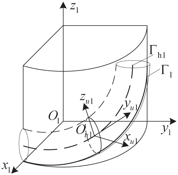
In the curve constructed worm drive, the trajectory of the contact points of the worm is a cylindrical helix and the equation of the cylindrical helix Г1 can be expressed in the following:

Where, R is the radius of the cylindrical helix, θ is the angle of helix, p is the pitch.
At any given point along the cylindrical helix Г1, it is possible to determine three vectors that are mutually orthogonal to each other, as illustrated in Figure 2. The vector α represents the tangential direction, β represents the principal normal direction, and γ represents the binormal direction. At the point P on the curve Г1, the normal vector n1 can be expressed by the principal normal vector and the binormal vector in any given direction. Hence, the normal vector n1 can be mathematically represented in any given direction as follows 27 :

Where, u and v are coefficients determined by the direction of the curve at point P.

Normal vector of cylinder helix and triangulation of curve.
Furthermore, according to the force relationship of the curve constructed worm drive at the contact points P, the solution to the relationship between the normal pressure angle and the principal normal and binormal vectors can be determined. This establishes that n n can be represented as the following equation:

Where, α n is the normal pressure angle.
In the rotating coordinate system S1, according to equations (2) and (3) above, the nor-mal vector n n in any direction of the cylindrical helix Г1 can be represented by the following equation:

Where, u = sin αn, v = cos α n , [βx1, βy1, βz1]T, and [γx1, γy1, γz1]T can be formulated as:

To simplify calculations, assume ω1 to be 1 rad/s. Consequently, the angular velocity, ω2, determined as i21 rad/s. In consequence, the relative velocity

The trajectory of contact for the curve constructed worm wheel is a conjugate curve, that is, produced by the cylindrical helix Г1. On the basic of the meshing principle, curves Г1 and Г2 should be tangential during meshing and satisfy the following properties:

Substituting equations (5) and (6) into equation (7), the engagement equation of the curve constructed worm drive is obtained as:

According to the coordinate change and meshing principle, the trajectory of contact points of the curve constructed worm wheel can be dealt with as:

Tooth surface
By equidistant the cylindrical spiral along the direction normal to the given pressure angle, as shown in Figure 3, with an equidistance of h1, the equation for the equidistance curve Гh1 can be obtained as follows:

Where h1 is the equidistant distance of equidistant curve Гh1 to worm contact trajectory.

Contact trajectory curves and the equidistant curves.
A circle can be created by taking the equidistant distance h1 as the radius and any point on the equidistant curve Гh1 as the center of the circle. A circular coordinate system Su (Ou, xu, yu, zu) is established, as shown in Figure 4. Any point Q on the circle can be determined by the parameters ϕ, together with the parametric equation of the circle can be obtained as follows:
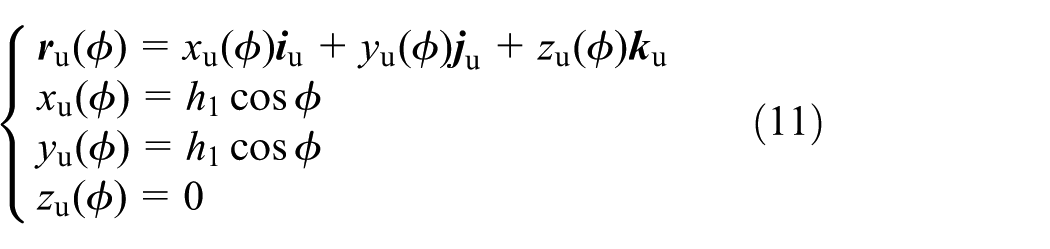
Where ϕ is the spiral parameter.
Coordinate system of the circle.
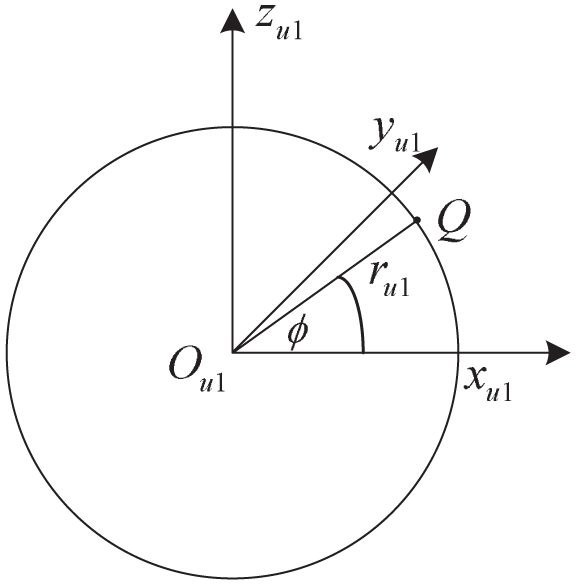
The surface Σ1 is generated by the continuous translation of the circle along the equidistant curve Гh1, as depicted in Figure 5. By employing a transformation relation from Su to S1, the surface Σ1 can be represented:

Where,
Circular swept round tube.
Through calculation, the tooth surface Σ1 has been determined as follows:

Where, R is the equidistant distance of constructed surface.
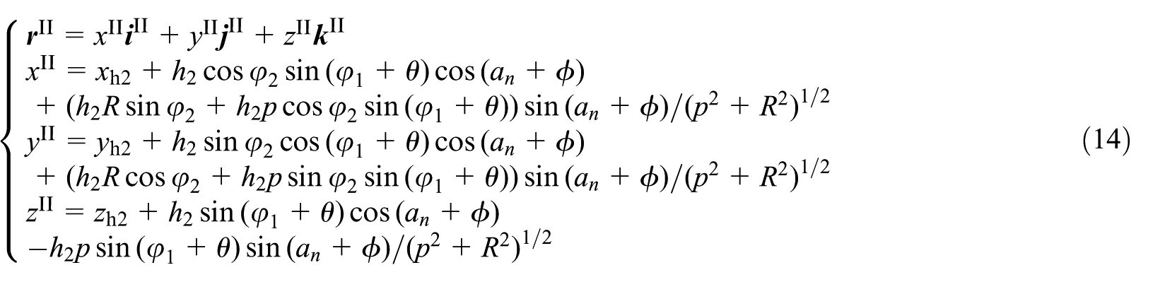
Similarly, the tooth surface Σ2 has been determined to be as follows:
As illustrated in Figure 6, the tooth surface on one side of the curve constructed worm drive, is respectively, generated by intercepting the above-mentioned surfaces Σ1 and Σ2 using the root and the tip cylindrical surface of the curve constructed worm and worm wheel, etc.

Intercepted tooth surface of the curve constructed worm drive.
Contact types
By adjusting the equidistant direction and equidistant distance along the normal equidistant curve, this point contact worm gearing can obtain three types of contact as shown in Figure 7.
Convex to convex contact: Considering curves Гh1 and Гh2 equidistant in opposite directions. By taking the positive and negative values of h1 and h2 in equations (13) and (14), the convex-convex contact mode is obtained.
Convex to plane contact: When the equidistance distance h2 between Г2 and Гh2 approaches infinity, the tooth profile curve of the worm wheel in the normal plane becomes a straight line, resulting in the attainment of the convex-plane contact mode.
Convex to concave contact: When the curves Гh1 and Гh2 have the same equidistant direction, that is, the parameters h1 and h2 take the same positive and negative, with h2 taking a larger value compared to h1, the convex concave contact is obtained.

Three types of contact for the curve constructed worm drive.
Constructed worm drive
By the method of constructing the tooth surfaces of the curve constructed worm drive described earlier. Selecting any of the contact types and then taking the appropriate parameters, the curve constructed worm drive can be constructed. As an example, a convex-plane contact mode of the curve constructed worm drive is constructed as depicted in Figure 8.

Convex-plane contact mode of the curve constructed worm drive.
Tooth contact analysis
Two-point contact characteristic
The above description indicates that the curve constructed worm drive is point contact. The surface of the worm tooth exhibits a cylindrical helix as the trajectory curve of contact. Obviously, the trajectory curve of contact on the worm wheel is part of the conjugate curve to the cylindrical helix on the worm. As shown in Figure 9, the green surface represents the worm gear tooth surface, and the red surface denotes the worm tooth surface. The intersecting area between the two is the meshing contact zone of the transmission pair. It can be observed that Figure 9(a) illustrates the meshing-in region of the curve constructed worm drive, presenting a long elliptical contact in the middle of the worm gear tooth surface. Figure 9(b) shows the mid-meshing region of the curve constructed worm drive, where the contact part splits into two short ellipses. Figure 9(c) depicts the meshing-out region of the curve constructed worm drive, with the two contact regions transforming into even shorter ellipses. During the course of the meshing process, these two contact points progressively move away along the contact trajectory. During the whole meshing process, the contact trajectory is V-shaped.
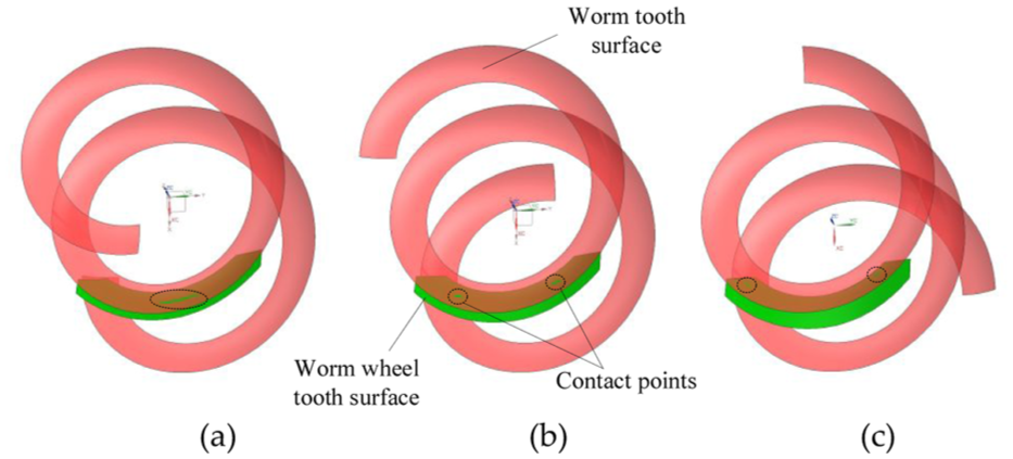
Two-point contact for the curve constructed worm drive: (a) begin of meshing, (b) middle of meshing, and (c) end of meshing.
Principal directions and curvatures
The process how the worm tooth surface is generated may be described by the movement of a tooth profile curve along the cylindrical helix Гh1. During meshing, at any contact point, the tangential vector of the tooth curve is always perpendicular to the tangential vector of the cylindrical helix. Therefore,

Where,
Similarly, the formation of the worm wheel tooth surface is easily described by the movement of a tooth profile curve along the conjugate curve Гh2. During meshing, at any contact point, the tangential vectors of the tooth curve and the tangential vectors of the generating line are perpendicular to each other, and the
Therefore, the principal curvature

Where,
Based on the engagement relationship between the tooth surfaces of the curve constructed worm drive, at the contact point,
Further analyzed, the relationship at the point of contact between the curvature of the cylindrical helix and the principal curvature of the tooth surface in the direction

Curvature relations for curve and curved surface.
δ represents the angle between the osculating plane and the normal plane of the tooth surface. On the basic of Meusnier theorem,
27
the mathematical equation that represents the curvature connecting the curve Гh1 and the worm tooth surface Σ1 in the direction

Combine with Figure 2, there exists the relation

Solve the curvature of Г1 and simplify. Substitute into equation (18) and the normal curvature

Similarly, the normal curvature

In the direction

Contact ellipse
The contact points of the two tooth surfaces experience pressure when the curve constructed worm drive meshes, resulting in elastic deformation. This deformation causes the formation of a transient contact ellipse as depicted in Figure 11.

Contact ellipse of the curve constructed worm drive.
Depending on Hertzian point contact theory 28 and gear geometry theory, 27 the mathematical description of the contact ellipse can be determined as:

Where, Δ represents the amount of elastic deformation. A and B are represented as:
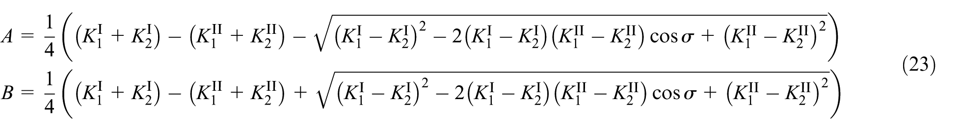
Where,
Induced normal curvature
The induced curvature quantifies how close two surfaces are along a particular tangential direction. This is also the important indicator for evaluating the strength of the contact between two surfaces. It represents the relative principal curvature of both tooth surfaces in worm gear transmission. Theoretically, a reduction in the induced normal curvature enables worm transmission to have better meshing characteristics.
According to the Euler equation the normal curvatures

Where, q1 is the angle between e and
Further,

Since the angle σ between the principal directions
The expression for the curvature of both tooth surfaces in the

Numerical examples
The design parameters are given in Table 1 to further analyze the curve constructed worm drive.
Design parameters of the curve constructed worm drive.

Contact trajectory
Contact points distribution is a significant index used to assess the meshing performance of worm transmission. Investigating the effect of key design parameters on the contact trajectory can contribute a valuable reference to the design of the curve constructed worm transmission.
While keeping parameters such as center distance unchanged, this analysis focuses on separately evaluating the effects of lead angle γ and normal pressure angle αn on the contact trajectory. Based on equation (2), the connection between γ and R can be presented as:
That is, when exploring the effect of the lead angle on the contact trajectory, it is possible to analyze it by considering the helix radius of the cylindrical helix, the modulus, and the numbers of worm threads. Figure 12(a) to (c) show the change in contact trajectory when one of the parameters is changed, respectively. Besides, the effect of normal pressure angle αn on the trajectory of contact is analyzed, as shown in Figure 12(d).

Contact trajectory of the curve constructed worm wheel surface: (a) helix radius R, (b) worm threads Z1, (c) axial module of the worm m xl , and (d) normal pressure angle a n .
From Figure 12, the contact points are projected onto the curve constructed worm wheel tooth surface whenever the worm is turned through an equal angle. The regularity of the contact point distribution throughout the meshing process is obtained.
Typically, the contact points exhibit a sparse distribution in proximity to the central region of the tooth surface, whereas they are densely distributed in close proximity to both sides of the tooth surface. In Figure 12(a) and (c), when the helical radius R of the cylindrical helix and the module m x 1 of the worm axial direction increase, the initial emergence location of the contact point moves towards the positive semi-axis of the y2-axis. From Figure 12(b), as the number of worm heads increases, the more dispersed the contact points will be. From Figure 12(d), it can be seen that αn exerts a marginal influence on the contact trajectory within the negative semi-axis of the y2-axis. Nevertheless, within the positive semi-axis of the y2-axis, the smaller the αn, the shorter the contact trajectory and the denser the distribution.
Contact ellipse
Since the value of elastic deformation does not influence the shape of the contact ellipse, given the elastic deformation Δ = 0.00635 mm, the laws of different parameters on the contact ellipse shape are discussed. According to equations (22) and (23), the size of the contact ellipse is related to
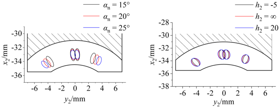
Contact ellipse of the curve constructed worm wheel surface: (a) normal pressure angle αn and (b) equidistant distance h2.
As shown in Figure 13(a), a modification of αn will lead to a change in the semi-major axis of the contact ellipse. As αn increases, there is a corresponding decrease in the value of the semi-major axis of the contact ellipse. From Figure 13(b), combined with equation (21), the semi-minor axis of the contact ellipse gradually converges to the red ellipse as h2 gradually converges to infinity.
Induced normal curvature
Based on equation (26), keeping h1 constant and changing the value of h2, the change of induced normal curvature
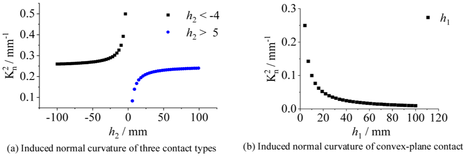
Induced normal curvature of the curve constructed worm drive: (a) induced normal curvature of three contact types and (b) induced normal curvature of convex-plane contact.
Finite element analysis of tooth contact
An accurate 3D model of the curve constructed worm drive is built according to the previously derived equations and considered the parameters given in Table 1. As presented in Figure 15, the 3D model is convex-plane contact.

Precision 3D modeling of the curve constructed worm drive.
To perform finite element static structural analysis on the 3D model, it firstly be simplified. Afterwards, the boundary conditions for the static structural analysis are set, as shown in Figure 16. Assuming the worm is stationary with respect to surface I which is fully constrained rigid. Besides, the worm wheel can only rotate around z1 as a result of applying cylindrical constraints on the rigid surface II. Define the material of the worm as structural steel, while the material of the worm gear is defined as PA66-GF50. Hexahedral mesh with 0.1 mm is used, and there are 823,566 elements with 1,332,573 nodes in the finite element model. Additionally, applying a torque T2 with 33 Nm on the rigid surface II.

Boundary conditions in finite element analysis.
Upon completing the finite simulation, Figure 17 illustrates the contact state of the curve constructed worm drive. Evidently, there are two points of contact between the worm surface and worm wheel surface. Therefore, the practical contact points are consistent with the above theory.

Contact points on the curve constructed worm wheel: (a) left tooth surface and (b) right tooth surface.
Now contact state is analyzed of the curve constructed worm drive at zero error. As presented in Figure 18, the contact state of the curve constructed worm drive is determined using finite element simulation. From Figure 18, the curve constructed worm drive exhibits the characteristic of two-point contact under the action of torque.
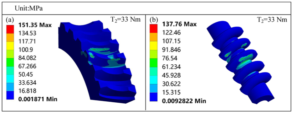
Tooth contact state of the curve constructed worm drive under zero error.
Error sensitivity analysis
The curve constructed worm drive is mainly designed to diminish the sensitivity of cylindrical worm drive to errors. It serves to reduce the machining accuracy requirement, reduce the break-in time and improve the industrial efficiency.
As shown in Figure 19, the error model of the curve constructed worm drive is created. It includes center distance error Δa, shaft angle error Δλ, worm axial error ΔL1, and worm wheel axial error ΔL2.

Error model schematic of the curve constructed worm drive.
Profile errors of tooth surface
Finite element analysis is carried out for the curve constructed worm drive, considering center distance errors of Δa = +0.1 mm and Δa = −0.1 mm, respectively. The tooth contact state is illustrated in Figure 20, taking center distance error into account.

Tooth contact state of the curve constructed worm drive under center distance error: (a) tooth surface of worm gear with Δa = + 0.1 mm, (b) tooth surface of worm with Δa = + 0.1 mm, (c) tooth surface of worm gear with Δa = − 0.1 mm, and (d) tooth surface of worm with Δa = − 0.1 mm.
From Figure 20, with Δa = +0.1 mm and Δa = −0.1 mm, the contact state of the curve constructed worm drive is still two-point contact. When Δa = +0.1 mm, the tooth surface contact stress increases by 10% compared to the zero error case. When Δa = −0.1 mm, the tooth surface contact stress is almost unchanged compared to the zero errors case.
Shaft angle error
The analysis of the tooth contact state of the curve constructed worm drive is conducted in the case of shaft angle error. As illustrated in Figure 21, finite element simulation of the tooth contact is performed under Δλ = +0.5° and Δλ = −0.5°.

Tooth contact state of the curve constructed worm drive under shaft angle error: (a) tooth surface of worm gear with Δλ = + 0.5°, (b) tooth surface of worm with Δλ = + 0.5°, (c) tooth surface of worm gear with Δλ = − 0.5°, and (d) tooth surface of worm with Δλ = − 0.5°.
From Figure 21, the contact points of the curve constructed worm drive are diminished under shaft angle error. In case of axis intersection angle error Δλ = +0.5°, the tooth contact stress increases by 26% compared to the zero error case. In case of axis intersection angle error Δλ = −0.5°, the tooth contact stress increases by 60% as com-pared to the zero errors case.
Axial error
As illustrated in Figure 22, the tooth contact state of the curve constructed worm drive under axial error is analyzed. The tooth contact state with axial error is analyzed using finite element simulation for the worm drive with variations of ΔL1 = +0.1 mm, ΔL1 = −0.1 mm, ΔL2 = +0.1 mm, and ΔL2 = −0.1 mm.
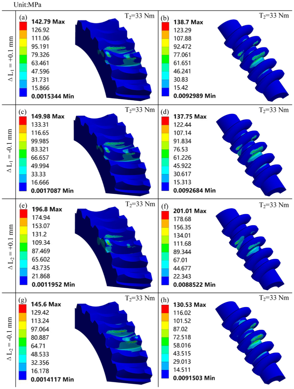
Tooth contact state of the curve constructed worm drive under axial error: (a) tooth surface of worm gear with ΔL1 = + 0.1 mm, (b) tooth surface of worm with ΔL1 = + 0.1 mm, (c) tooth surface of worm gear with ΔL1 = − 0.1 mm, (d) tooth surface of worm with ΔL1 = − 0.1 mm, (e) tooth surface of worm gear with ΔL2 = + 0.1 mm, (f) tooth surface of worm with ΔL2 = + 0.1 mm, (g) tooth surface of worm gear with ΔL2 = − 0.1 mm, and (h) tooth surface of worm with ΔL2 = −0.1 mm.
From Figure 22, the tooth contact state of the curve constructed worm drive remains practically unchanged for the worm axial errors ΔL1 = +0.1 mm and ΔL1 = −0.1 mm. The stress on the tooth surface is even decreased compared to the zero error case. For the worm wheel axial error ΔL2 = +0.1 mm, the tooth surface stress increase by 30%. However, when ΔL2 = −0.1 mm, the tooth surface stress is basically unchanged. There-fore, positive the worm wheel axial errors should be avoided as much as possible of the curve constructed worm drive.
Conclusions
In the research performed in the paper, the following conclusions are obtained:
The curve constructed worm drive with curve conjugation is proposed, presenting a mathematical model for this novel transmission, and this transmission exhibits three types of tooth contact modes.
The TCA of the curve constructed worm drive is presented. The verification of the characteristic of two-point contact of the curve constructed worm drive is conducted through finite element static structure analysis.
The model to analyze the error sensitivity of the curve constructed worm drive has been developed. This study employs finite element analysis to investigate the error sensitivity in terms of center distance, shaft angle, and axial errors. The curve constructed worm drive exhibits excellent adaptability to center distance and axial errors. However, it is relatively poorly adapted to shaft angle errors.
Footnotes
Handling Editor: Chenhui Liang
Funding
The authors disclosed receipt of the following financial support for the research, authorship, and/or publication of this article: This research was funded by the National Natural Science Foundation of China (52575050), Scientific and Technological Research Program of Chongqing Municipal Education Commission (KJZD-K202204401, KJQN202404405), and Center for Artificial Intelligence Applied Technology Outreach (2025XJZX04).
Declaration of conflicting interests
The authors declared no potential conflicts of interest with respect to the research, authorship, and/or publication of this article.