
Abstract
The “tube-to-tubesheet” joint expanded hydraulically plays a key role in many industrial applications, such as heat exchangers and boilers. These joints consist of three zones: Expanded zone, unexpanded zone, and a transition zone. This process generates residual stresses in the transition zone, influencing the durability, tightness, and reliability of these joints. The transition zone constitutes the weakest link of this joint, due to the presence of high axial residual stresses produced during the expansion process which, coupled with other service loads can lead to its failure. Hence, estimating the residual stresses in the transition zone caused by the expansion process is crucial for optimal joint design. The analytical model developed in this paper has shown that the equivalent residual stresses can reach 76% of the yield stress of the tube material and that the residual axial stresses reach 88% of the yield stress and the hoop stresses can reach 55% of the yield stress. It has also been shown that the stresses are maximum at the inner diameter of the tube. This study has provided an analytical model capable of predicting the residual stresses in this joint as a function of the expansion pressures, which is important for optimal sizing of the joint. A finite element analysis will be used to validate the analytical model.
Introduction
Industrial installations such as heat exchangers, steam generators, and boilers use so-called tube-to tubesheet joints. To ensure the tightness between the two fluids circulating in these joints, the hydraulic expansion process is often used, which consists of closing the clearance between the tube and the tubesheet by hydraulic pressure exerted on the inner surface of the tube. This process causes residual stresses to develop in the joint which will be added to the stresses induced in service and this can result in the failure of the joint if these residual stresses are not taken into consideration in the design phase of these joints.
These joints consist of three zones: Expanded zone, transition zone, and unexpanded zone (Figure 1).

Tube-to-tubesheet joint geometry.
The expanded zone has been the subject of research by several researchers such as Laghzale and Bouzid 1 who have studied this zone in several papers and with several material behaviors:
Elastic perfectly plastic behavior 1 : In this article, they proposed an analytical model that expresses the residual contact pressure that is at the origin of the tightness of the joint.
Bilinear behavior 2 : In this article they developed a model that predicts the residual stresses in this zone and taking into account the hardening.
Stovpnyk et al. 3 conducted an experimental study to analyze the influence of the initial clearance between the tube and the tubesheet on the residual stresses in a mechanically expanded joint. Their work, based on measurements of clearances and residual stresses, showed that the highest stress levels occur when the initial clearance reaches or exceeds 0.40 mm.
Thekkuden et al. 4 analyzed the combined influence of expansion percentage and grooving conditions on the mechanical and metallurgical properties of tube-to-tubesheet joints, both purely expanded and hybrid welded-expanded types. The results showed that poor weld quality significantly reduces the joint’s strength. For joints produced solely by expansion (without welding), pull-out tests revealed that the tubes detached from the tubesheet under all grooving conditions and for expansion percentages ranging from 4% to 10%.The authors recommend using tubesheets thicker than 23 mm for heat exchangers manufactured exclusively by the expansion process.
Hong et al. 5 investigated the influence of initial clearance between the tube and the tubesheet, expansion pressure, and material yield stress on the residual stresses in a hydraulically expanded joint made of stainless steel 304 L. The residual stresses were evaluated both experimentally and numerically. The results showed that the maximum residual stress in the expanded joint occurs when the initial clearance is completely closed. Moreover, the residual stress level decreases with the reduction of the initial clearance and the yield stress of the tube material.
Scott et al. 6 studied, experimentally, the joint using the X-ray diffraction method, stress corrosion cracking tests, and strain gauge measurements. The authors concluded that these three methods found approximately the same results. They also found that hydraulic expansion generates acceptable residual stresses, and that ground tubes should preferably be annealed to achieve low residual stresses.
On the other hand, the transition zone, although it constitutes the critical zone of these joints, has attracted less research. It was studied analytically for the first time in 1988 by Updike et al. 7 These authors returned in 1992 to study this zone a second time based on the theories of beams on elastic foundations and they found that the axial residual stresses reach about 94% of the yield stress of the tube material in the inner diameter of the tube while the hoop residual stresses can reach 60% of the yield stress of the tube material in the inner diameter. 8
Allam et al. 9 studied the transition zone. The analytical model they developed is based on beam on elastic foundation theories with a plane stress state. They found that the axial residual stress varies between 86% and 109% of the yield stress, while the hoop stress ranges between 55% and 68%.
Bouzid and Pourreza 10 studied this zone by dividing it into two zones: A plastic zone with rigid perfectly plastic behavior, which is not the case for the case they studied, and a second elastic zone on which they used the Theories of beams on elastic foundations applied to thin cylindrical shells. The authors found that the axial and hoop residual stresses reach the yield stress at the beginning of the transition zone and at the inner diameter of the tube.
The mathematical model presented in this article is based on dividing the transition zone into two distinct regions: an elastic region and a plastic region. This approach has been used by other researchers; however, the originality of the present work lies in the assumption made regarding the variation of the tube’s mean diameter within the plastic region of the transition zone. The proposed model makes it possible to predict the residual stresses in this zone as a function of the expansion pressures. This prediction is of dual interest: on one hand, to determine the optimal pressures that ensure good tightness, and on the other hand, to avoid stress levels that could compromise the integrity of the joint. Finally, a finite element analysis will be carried out to validate the analytical model developed in this study.
Analytical approach
To analyze the residual stresses in the transition zone, a cross-section is made at this location of the tube, thereby dividing it into two parts:
A predominantly plastic region on the side of the expanded zone, with a very thin elasto-plastic region that is neglected for simplification.
An elastic region on the side of the unexpanded zone (Figure 2).

Schematic representation of the tube showing the expanded, transition, and unexpanded zones.
Assumptions and basic equations
The mathematical model proposed to evaluate the residual stresses in the transition zone of the hydraulically expanded tube is based on the following assumptions:
An elastic perfectly plastic behavior of the tube and tubesheet materials.
The tube and the tubesheet are considered as axisymmetric bodies with a plane state of deformation, their materials are incompressible and the limiting criterion applied is that of Tresca.
For the plastic region of the transition zone (the elasto-plastic region being neglected), it is assumed that the displacement of the average radius of the tube, during the loading of the tube, varies according to the following function:

Where the coordinate
The elastic region is considered as a long cylindrical shell.
Long shell theories (similar to beam on elastic foundations theories) give the following expressions 11 :
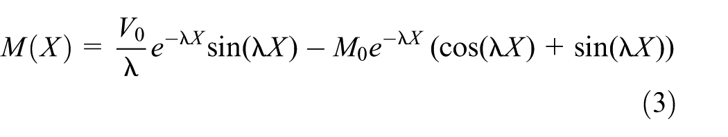
The axial stress and the hoop stress are described as equation (2), respectively:

Where the coordinate
Where:
When

Consider the following edge conditions to determine M0 and V0:
- Both functions equations (1) and (4) have the same value for

- On the other hand, it is assumed (hypothesis) that the two functions also have the same derivative for

By solving equations (6) and (7), M0 and V0 are obtained as equation (8), where they are a function of

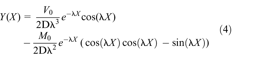
Substituting equation (8) in equations (3) and (4) the following equations (9) and (10) are obtained:


The final expressions of the stresses


The (+) sign is for the inner diameter and the (−) sign is for the outer diameter.
To determine these two stresses, it is sufficient to know the displacement
These two stresses are expressed as equation (13) for x = 0 (beginning of the elastic region):

And the equivalent Von Mises stress is:

This expression enables the evaluation of the plasticized length. The next step consists in determining the displacement
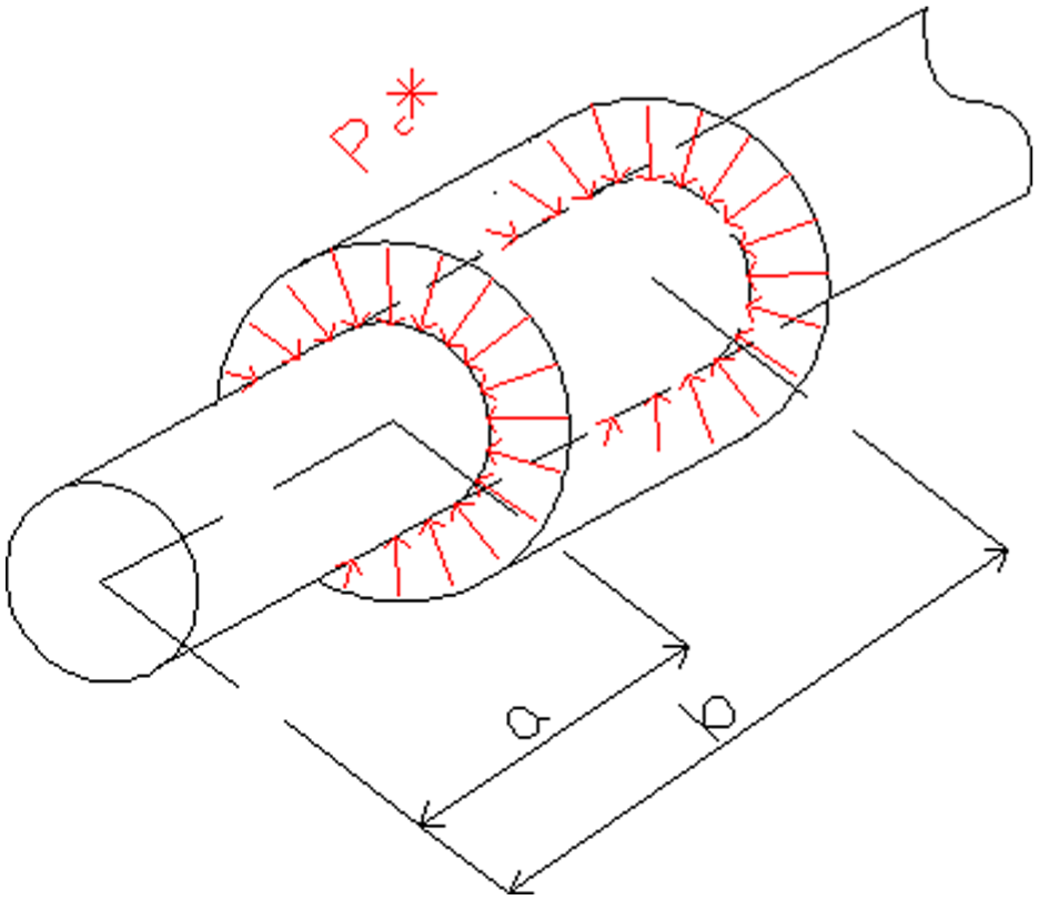
Phases of the expansion process (for the different phases of expansion, the results from Laghzale and Bouzid 1 will be taken into consideration)
The study of the different phases of expansion of the expanded zone, which will allow determining

The expansion phases of the expanded zone.
Phase 1: Elastic deformation of the expanded zone of the tube (a–b)
In this phase the expanded zone of the tube deforms elastically up to the pressure which causes the start of plasticization of the tube
Considering the tube as an open thick cylinder, the displacement of the average radius in the expanded zone is obtained as equation (17):

The displacement of the average radius at the end of the elastic phase of the expanded zone is obtained as equation (18) by replacing

And the plastic length
And the stresses in the elastic region of the transition zone at the end of this phase are obtained by substituting equations (15) and (18) into equations (11) and (12).
Phase 2: Plastic deformation of the expanded zone of the tube and closing of the gap (b–c)
Beyond
Beyond the plastic collapse pressure . the tube deforms plastically until the gap closes.
This plastic collapse pressure is:

Assuming that the entire thickness of the tube plasticizes before it comes into contact with the tubesheet, it is possible to determine the displacement of the average radius at the closing of the gap.
The geometric relationships are given by:

Incompressible materials involve:

By substituting equations (20) in (21) and after integration, equations (22) is obtained
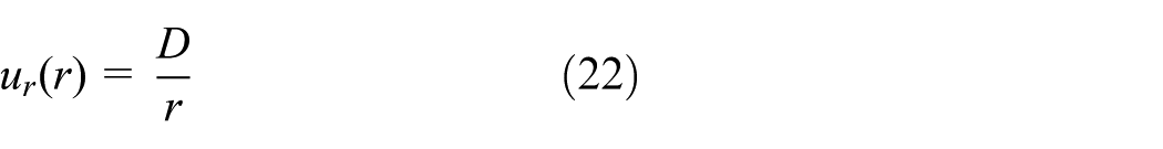
where
When the gap is closed,

The displacement of the average radius is given by

By substituting equations (23) in (24), the following equation (25) is obtained:

And the plastic length
And the stresses in the elastic region of the transition zone at the end of this phase are obtained by substituting equations (15) and (25) into equations (11) and (12).
Phase 3: Elastic deformation of the tubesheet (c–d)
Once the tube comes into contact with the tubesheet it begins to deform it elastically while it continues to deform plastically.
The contact pressure which is responsible for the deformation of the tubesheet is given by:

The displacement of the outer radius of the tube is obtained by considering the geometric compatibility from moving the interface:

where
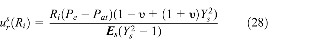
where
And the displacement of the average radius of the tube at the end of this phase is obtained from equation (24), where D is expressed by equation (29):
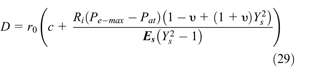
By substituting equations (29) in (24), the following equation (30) is obtained, giving the displacement of the average radius at the end of this phase:

And the plastic length
And the stresses in the elastic region of the transition zone at the end of this phase are obtained by substituting equations (15) and (30) into equations (11) and (12).
Phase4: Elastic unloading without elasto-plastic deformation of the tubesheet and no reverse yielding (d–e)
During unloading, the tube and the tubesheet deform elastically and the contact pressure is obtained by analyzing the displacement of the interface:

During unloading the relative displacements are given by:


Which gives:
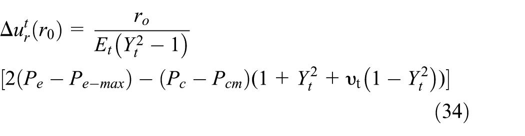

By equating equations (34) and (35), equation (36) is obtained:

where:

And the residual contact pressure is obtained by equation (36) by setting

where:

Substituting (39) in equation (38), the following equation (40) is obtained:

The unloading stresses in the transition zone during this phase are obtained considering the tube as a thin, infinitely long cylindrical shell and subjected to uniform pressure
Long tube subjected to uniform pressure from (a) to (b).
And the axial and hoop unloading stresses are respectively

where:

The various parameters which make it possible to determine
And finally the residual stresses in the elastic region of the transition zone are obtained from the following expression:

where:
Numerical finite elements model
The analytical model was validated by a simulation using the software (ANSYS Workbench 18.1). The model is 2D, and the material behavior is elastic perfectly plastic. The joint is modeled using surface bodies, and the tube length beyond the tubesheet is sufficient to avoid discontinuity edge effects (Figure 5). The American Society of Mechanical Engineers (ASME) code suggests that this length should be five times the attenuation length
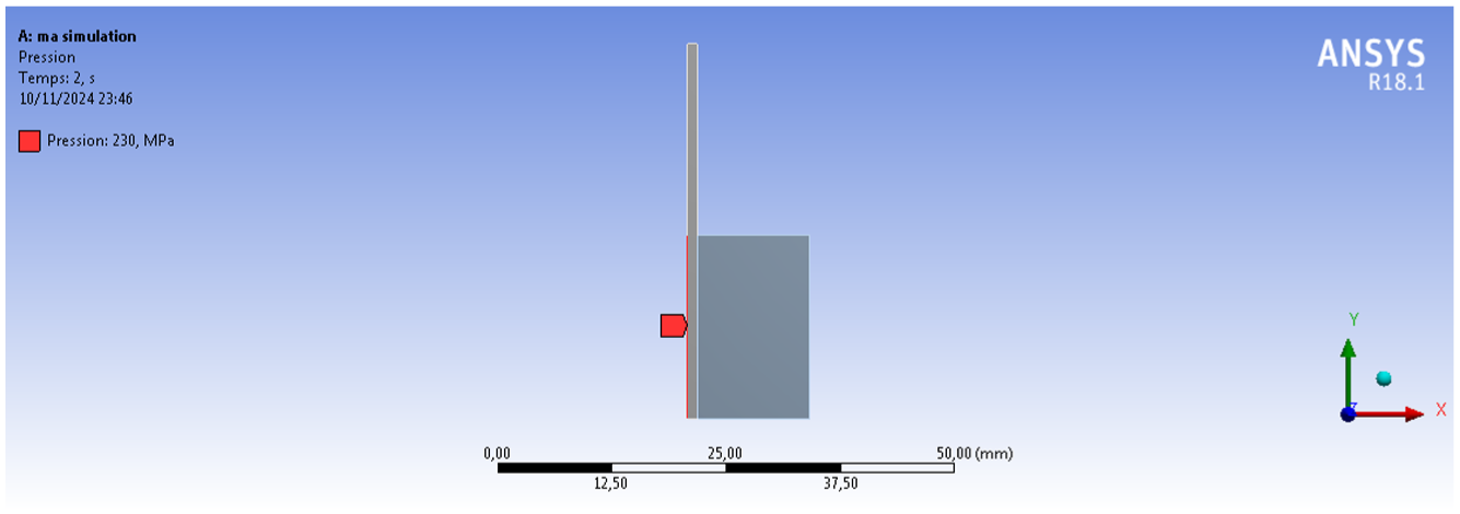
An image of the joint simulation.
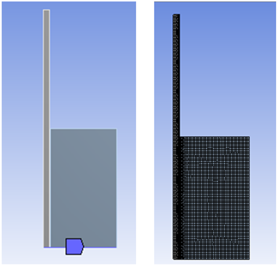
The support used is on the left, and the mesh is on the right.
Geometry and mechanical properties of joint.

Results and discussion
The maximum expansion pressure was chosen to avoid plastic deformation of the tubesheet which starts from
The plastic collapse pressure of the tube is
At the end of the loading phase, the plasticized length of the transition zone is
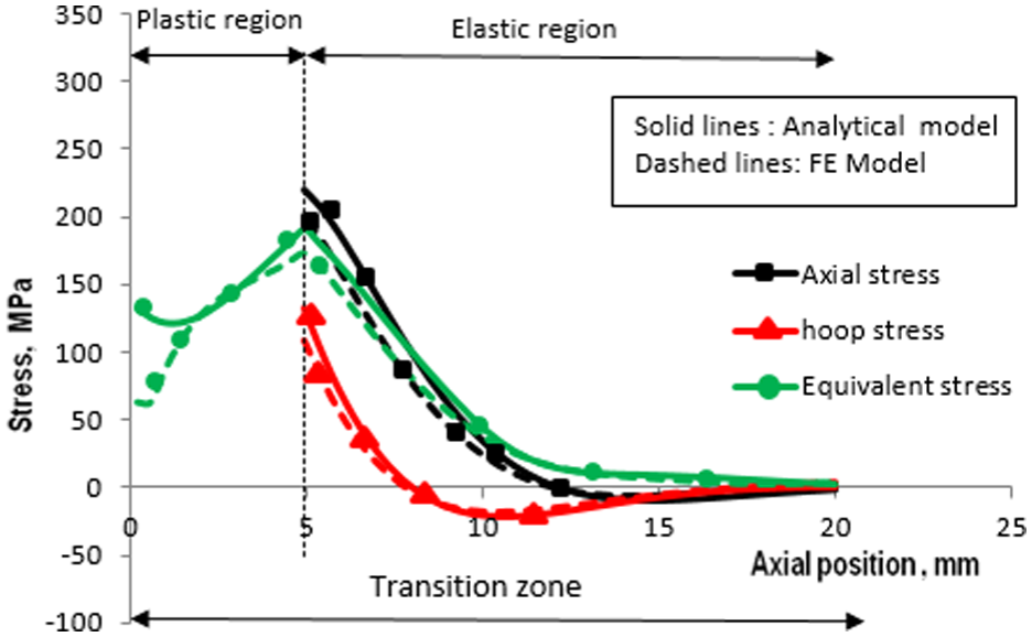
Figure 7 shows that there is good agreement between the analytical model and the numerical model.

Comparison of stresses in the inner diameter of the tube at the end of the loading phase in the transition zone.
At the beginning of the elastic region of the transition zone, the discrepancy between the numerical and analytical axial stresses is 2.4% of the numerical σx, which is lower than the 4% difference reported byBouzid and Pourreza. 10 The analytical axial stress exceeds the yield stress at the end of the elastic region and it represents about 114% of the yield stress.
At the beginning of the elastic region of the transition zone, the discrepancy between the numerical and analytical hoop stresses is 6% of the numerical
The comparison between the residual stresses at the inner diameter and at the end of the unloading phase is shown in Figure 8. The difference between the numerical and analytical model at the beginning of the elastic region of the transition zone is 8% of the analytical value for axial stresses and 17% of the analytical value for hoop stresses while for equivalent stresses it is 7%.The analytical axial residual stress in the inner diameter and at the beginning of the elastic region of the transition zone is 88% of the yield stress and the hoop residual stress is 55% and the equivalent residual stress is 76% of the yield stress. These results are in good agreement with the literature.
Comparison of residual stresses in the inner diameter of the tube at the end of the unloading phase in the transition zone.
The comparison between the stresses in the outer diameter is in Figures 9 and 10 and the agreement between the two models is of the same order as for the inner diameter except for the hoop stress which represents a difference in appearance that deserves particular attention.

Comparison of stresses in the outer diameter of the tube at the end of the loading phase in the transition zone.

Comparison of residual stresses in the outer diameter of the tube at the end of the unloading phase in the transition zone.
Conclusions
The analytical approach described in this paper provides a solid basis for estimate residual stresses in hydraulically expanded joints. However, for a complete and robust assessment, it is combined with numerical analyses for prediction through powerful software. This integrated approach allows improving the performance and reliability of tube-to tubesheet joint, while optimizing their manufacturing. In fact, this analytical model that was developed in this article also allowed to determine the plasticized length of the transition zone at the end of each expansion phase, then to evaluate the stresses at the end of each expansion phase, and finally to determine the residual stresses in the inner and outer diameter of the tube in the transition zone, a very important thing that must be taken into consideration in the dimensioning phase of these joints.
The following observations can be made:
The equivalent residual stress is maximum at the inner diameter and can reach 76% of the yield stress at the beginning of the elastic region of the transition zone.
The axial residual stress is maximum at the inner diameter and can reach 88% of the yield stress at the beginning of the elastic region of the transition zone.
The hoop residual stress is maximum at the inner diameter and can reach 55% of the yield stress at the beginning of the elastic region of the transition zone.
Using a general behavior material with the same analytical approach will be more realistic than an elastic perfectly plastic behavior.
Although in this work, essentially, the equivalent residual stress has been determined in the plastic region of the transition zone, nevertheless the determination of the axial and hoop residual stresses in this region will be better.
Footnotes
Appendix
Handling Editor: Aarthy Esakkiappan
Funding
The authors received no financial support for the research, authorship, and/or publication of this article.
Declaration of conflicting interests
The authors declared no potential conflicts of interest with respect to the research, authorship, and/or publication of this article.