
Abstract
Hot isostatic pressing (HIP) equipment relies on cylindrical gas containers reinforced with prestressed wires to withstand high internal pressures. Traditionally, the design of these wire-wound cylinders has largely depended on engineering experience, and often neglecting the effects of thermal stress, which limits the ability to achieve optimal design. To address this challenge, this study proposes an automated optimization framework based on the penalty method, systematically considering key design requirements including static strength, stability, and thermo-mechanical coupled performance. The optimization problem, involving multiple design variables and constraints, is solved using Differential Evolution (DE) and Non-dominated Sorting Genetic Algorithm (NSGA-II) to identify optimal wire-winding configurations. A representative optimized cylinder satisfying strength, buckling, and thermal requirements is verified through finite element analysis. Results show excellent agreement with analytical predictions, with coefficients of determination exceeding 0.99 and most relative errors well below 15%. The proposed framework provides a valid and practical tool for the intelligent design of HIP cylinders, enabling improved performance and material efficiency in engineering applications.
Keywords
Introduction
Hot isostatic pressing (HIP) is a material processing technique invented in 1950s, and now is widely used for the manufacturing of advanced materials with ultrahigh mechanical performance. 1 By imposing uniform ultrahigh gas pressure onto each accessible surface of the treated component at an ultrahigh-temperature environment, the body can be further densified and internal defects will be effectively eliminated. Thus, the strength, fracture toughness, fatigue life as well as anti-corrosion capability of the material can be drastically enhanced. Engineering experience shows that the material can achieve over 99% of full density after HIP treatment. 2 Apart from post-processing of components like special ceramics and additive manufactured metallic materials, the combined HIP and powder metallurgy process which is so-called Near Net Shaping-HIP (NNS-HIP), is able to fabricate and consolidate materials in one single cycle, remarkably improving material property and manufacturing efficiency. 3 HIP equipment includes several important systems, which are respectively main system, heating and insulating system, gas and cooling system, and control system. Among them the main system plays the role of “backbone” in the overall HIP installation, used to withstand ultrahigh internal gas pressure. The main system comprises of the following parts: pressure vessel, top and bottom closures, and frames. The pressure vessel is constructed by three layers: cylinder at the inner layer, used to contain and seal high pressure gas; water jacket at the middle layer, used for heat dissipation; prestressed wires at the outer layer, used to offer prestress to the cylinder. The structure of HIP pressure vessel is illustrated in Figure 1. By exerting initial tensile stress (i.e. winding stress) on the steel wires and surrounding them on the cylinder, prestress is generated in the cylinder which is beneficial for improving its load capacity. This technique is so called wire winding which was firstly proposed by Longridge at the end of 19th century. 4 Compared to other methods to reinforce pressure vessel, such as autofrettage and shrink-fit, wire winding has several outstanding advantages: easy to control prestress distribution, easy installation, low cost, high-level safety, and fitness to large-scale equipment construction, hence is generally used for HIP installation.5–7 The control of prestressing is based on different principles. Longridge firstly proposed to use constant winding stress for the wires, which is considered as the simplest case. Comstock 8 and Manning and Labrow 9 investigated the principle of constant tension wire winding based on maximum stress criterion, which ensures that all the wire layers can achieve the maximum allowable tensile stress at working state. In 1970s, Gronbaek and Wanheim 10 and Yan 11 independently proposed the constant shear stress wire winding technique based on maximum shear stress criterion. By manipulating variable winding stresses at different wire layers, all the wires can reach the maximum allowable shear stress during working state. The constant shear stress method aligns well with the failure characteristics of high-strength steel wires and is now the most widely adopted technique in engineering applications of wire-wound pressure vessels.
Illustration of HIP pressure vessel construction.
Recent studies have been done for the optimization design of wire-wound pressure vessels. Hajmohammad et al. 12 employed the distortion energy theory based on the von Mises criterion to optimize wire-wound vessel configurations, aiming to reduce the overall size and weight of pressure vessel installations. Sedighi et al.13,14 explored a hybrid reinforcement approach that combines wire winding and shrink-fit techniques for thick-walled cylinders, demonstrating significant potential for improving the fatigue performance of such components. Elfar et al. 15 proposed an analytical method to predict the residual stress distribution in thick-walled cylinders subjected to combined autofrettage, shrink-fit, and wire-winding processes. This method was subsequently integrated into a machine-learning-based framework to enhance fatigue life prediction. 16 In recent years, automatic and intelligent design concepts have been widely incorporated into the optimization of pressure vessels. Liu et al. 17 developed an improved genetic-algorithm-based strategy to achieve minimum-weight designs for pressure vessels. Mohammed and Rashid 18 introduced a hybrid optimization framework combining grey wolf optimization and the whale optimization algorithm, which demonstrated enhanced robustness in searching for global optima in pressure vessel design. Alcántar et al. 19 investigated the application of evolutionary optimization techniques, including genetic algorithms and simulated annealing, for lightweight design of composite pressure vessels. However, a noticeable research gap remains in the optimization method as well as the development of automatic design tool of HIP cylinders, particularly under the combined influence of mechanical and thermal stress constraints. This study addresses this gap by proposing a computational automatic optimization strategy specifically for HIP cylinder design, incorporating significant safety requirements, including allowable stress limits, buckling resistance, and thermal stress effects.
To validate the proposed optimization scheme, finite element analysis (FEA) is performed. In the simulation of the wire-winding process, an equivalent approach is adopted, in which the prestress is represented by an equivalent thermal stress generated through the application of a negative temperature difference in each wire layer.20,21 In addition, the element birth and death technique can be employed to model and control the sequential layer-by-layer winding process. 22 These methodologies will serve as references for the FEA implementation and verification in this work.
Design method of HIP cylinder
Balance relationship
The balance relationship of HIP cylinders is based on Yan’s prestress theory. 11 During operation, the HIP cylinder is subjected to an extreme environment with high pressure and elevated temperature. From a safety perspective, it is essential that the HIP cylinder remains under compressive stress throughout the entire service cycle to prevent crack initiation and propagation through the wall thickness. To characterize the stress state and ensure structural stability, Yan introduced the prestress coefficient η to describe the equilibrium condition of wire-wound cylinders. This coefficient is defined as follow:

Where σ gti is the hoop stress on cylinder’s inner surface in prestress state, σ pti represents the hoop stress on the inner surface induced by the internal gas pressure. It follows that when η > 1, the cylinder remains in a compressive state throughout the entire operational cycle.
During working condition, each wire layer achieves the same allowable shear stress, and the radial stress distribution within the wire layers along thickness direction is expressed as:

Where

Where P i is the internal gas pressure, r i is the inner radius of cylinder, r j is the innermost radius of wires. For the convenience of calculation, two variables are introduced:
Thus, equation (3) can be simplified as:
Where r o can also be deduced by applying Lame’s equation:

To ensure that the cylinder is always compressive, as well as to prevent the cylinder from deforming too much under prestress, η is generally chosen within a range of 1.05–1.1.
Strength requirement
The strength design of cylinder and wires are all based on maximum shear stress criterion (Tresca’s criterion). For cylinder, its critical condition is prestress state, with the maximum allowable stress defined as
Since the cylinder is subjected to compressive stresses, which are generally considered safer than tensile stresses, its allowable stress can be set at a higher level. For cylinders forged from high-strength steel alloys, the minimum safety factor n1 can be specified as 1.3 approximately. Contrarily, the wires experience tensile stresses throughout the operating cycle, their stress levels should be maintained well below the allowable limit to ensure structural integrity and extend fatigue life. Additionally, according to the ASME Boiler and Pressure Vessel Code (BPVC) Section VIII, Division 3, for wires containing welded joints, the maximum equivalent stress must not exceed the weld strength, defined as two-thirds of the material’s yield strength. 23 Thus, the wires must have a relatively high safety factor, generally around n 2 = 2.
Anti-buckling requirement
During prestress state, the cylinder is subjected to compressive stress from the external pressure exerted by the wound wires. Therefore, its buckling behavior must be assessed. According to theory of elasticity developed by Timoshenko and Goodier, 24 the following criterion should be satisfied to ensure that the cylinder remains stable against buckling:
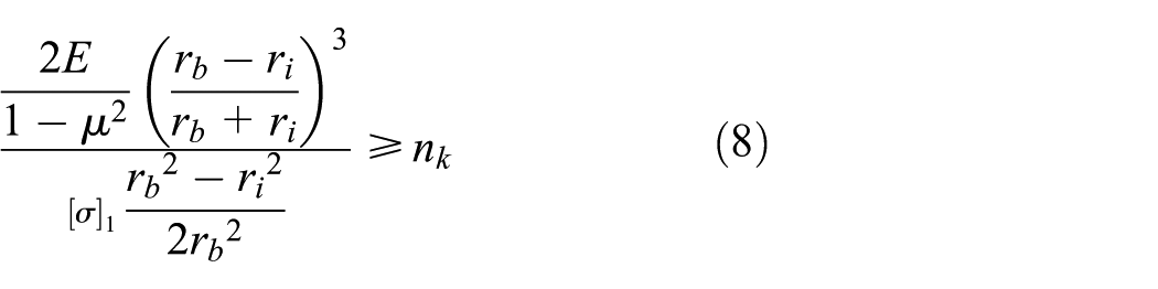
Where E is the elastic modulus and μ is Poisson’s ratio, r b is the outer radius of the innermost cylinder, n k is defined as anti-buckling safety ratio which is generally settled around 2. It should be noted that the water jacket is a segmented cylindrical structure and remains under compressive stress throughout the operational cycle, its stress distribution is comparable to that of a monolithic structure. Therefore, for design purposes, the cylinder and the water jacket can be considered as a single integrated body. However, the buckling behavior of the innermost cylinder must be evaluated separately after the design is finalized.
Thermal stress under steady state
During working state, non-uniform thermal expansion within the cylindrical body leads to the development of thermal stresses. In addition, the expansion of the cylinder induces further constraint forces from the surrounding prestressed wires, which must also be taken into account in the stress analysis. Based on the principle of superposition, the effects of prestress and thermal expansion can be calculated independently, and the combined thermo-mechanical response is obtained by superimposing these two contributions. This method was first proposed by Liu et al., 25 and in this study, the detailed implementation procedure based on displacement continuity is presented, which will be further validated in the following finite element analysis sections.
Under steady-state thermal conditions, the temperature distribution within the cylinder along the radial (thickness) direction can be expressed as follow 26 :
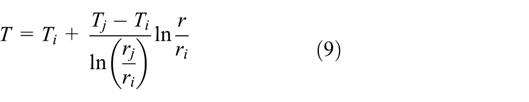
Where T i is the internal surface temperature of the cylinder and T j is the external surface temperature of water jacket during working state. The thermal stress distribution of the cylinder is deduced as 26 :

Where α is thermal expansion coefficient; C1, C2, and k are constants to be determined. For a cylinder only withstand temperature gradient and has no other constraints, its boundary condition can be defined as:

Substituting equation (11) into equation (10), it can be deduced that:

By solving equation (12), C1, C2, and k can be determined and the thermal stress distribution of the cylinder can be subsequently obtained.
To calculate the additional pressure exerted by the wires due to thermal expansion, the wire-wound assembly can be modeled as a two-layer cylindrical structure with zero initial interference, in which the cylinder and water jacket assembly are treated as the inner layer, and the wire assembly as the outer layer. Let the additional interface pressure induced by thermal expansion be denoted as
The radial interface displacement of inner layer (i.e. the cylinder and water jacket assembly) resulted by the additional interface pressure is:

The radial interface displacement of inner layer resulted by temperature gradient is:

Where T0 is the room temperature.
The radial interface displacement of outer layer (the wires) resulted by the additional interface pressure is:

The displacement continuity at interface requires that:

Thus, the additional interface pressure can be determined:
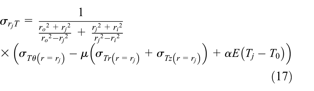
According to the principle of superposition, the compound stress on the inner surface of the cylinder in working condition is:

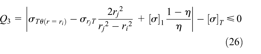
Based on the maximum stress criterion, it should be satisfied that:

Where
Based on these deductions, the optimization design framework of HIP cylinder can be established.
Optimization of HIP cylinder based on penalty method
Fundamental principle of penalty method
As discussed in section “Design method of HIP cylinder,” the optimization design of the HIP cylinder can be formulated as a nonlinear programming (NLP) problem, characterized by single or multiple objective functions, multiple design variables, and multiple constraint conditions. For such problems, the application of penalty method provides an effective approach to handle constraint violations within the optimization process.
Defining an optimization problem with constraints as follow 27 :

Based on penalty method, this problem can be transformed to:

In penalty method, the objective function f(x) is augmented with a penalty term cP(x), where c is the penalty factor and P(x) represents the constraint violation function. Thus, the original constrained optimization problem of minimizing f(x) is transformed into an unconstrained problem of minimizing
Implementation of penalty method
Optimizing the cylinder weight
The mathematical model of HIP cylinder optimization can be established as discussed in section “Design method of HIP cylinder.”
For a HIP cylinder with fixed inner diameter, to minimize its cost/weight, the objective function is defined as:

Given that the thickness of the water jacket,

Since the prestress coefficient η is also predetermined before design, it will be eliminated from optimization as well. Therefore, there are three variables involved in optimization process:
Three constraint conditions are defined as follows.
Constraint 1 (balance requirement): the force and stiffness balance should be achieved for the overall wire-wound cylinder assembly:

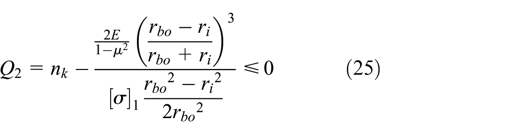
Constraint 2 (anti-buckling requirement): the safety factor to against buckling should not be less than n k :
Constraint 3 (Safety requirement considering thermal stress): based on the maximum stress criterion, the cylinder’s thermo-mechanical stress under actual operating conditions must not exceed the allowable stress.
Thus, the objective function can be transformed into the following form based on penalty method:

This penalty-based single-objective optimization model is a nonlinear constrained problem with continuous design variables. The Differential Evolution (DE) algorithm was adopted as the solver owing to its global search capability and robustness in handling such problems. DE is a population-based stochastic optimization method that evolves candidate solutions through mutation, crossover, and selection operators. It does not rely on gradient information and is therefore well suited for nonlinear and nonconvex optimization problems with continuous variables. 28 In preliminary tests, the DE algorithm exhibited stable convergence behavior and reliable performance, making it an appropriate and efficient choice for solving the present structural optimization problem.
Optimizing both cylinder weight and wire layer count
Generally, there exists a negative correlation between the cylinder weight and the number of wire layers. Minimizing the cylinder weight typically requires an increased number of wire layers to maintain the overall stiffness of the wire-wound assembly. However, the cost associated with the steel wires is non-negligible, particularly for large-scale HIP equipment. Therefore, a multi-objective optimization considering both the cylinder weight and the number of wire layers is necessary.
Following the same principles outlined in section “Optimizing the cylinder weight,” the objective function can be defined as:

Here, f1 denotes the penalty function corresponding to the cylinder weight, while f2 represents the penalty function associated with the number of wire layers. Instead of assigning fixed weighting coefficients to the two objective functions, applying a multi-objective optimization algorithm is more effective for addressing such problems.
The Non-dominated Sorting Genetic Algorithm II (NSGA-II), proposed by Deb et al., 29 integrates two key mechanisms: non-dominated sorting and crowding distance, into the conventional GA framework. NSGA-II is capable of producing a set of Pareto-optimal solutions, none of which is dominated by others in the objective space.
By employing NSGA-II in the optimization of HIP cylinder design, a balanced trade-off between cylinder weight and the number of wire layers can be achieved, providing flexible solutions for engineering applications.
Case studies and optimization results
In the case studies, the optimization of the HIP cylinder installation is characterized by two distinct modes: single-objective optimization, which exclusively targets the minimization of cylinder weight; and multi-objective optimization, which seeks to identify optimal trade-off solutions that balance a lightweight cylinder design with reduced wire consumption.
Single-objective optimization of the cylinder weight
This case study is to optimize the cylinder weight/cost of a HIP prototype based on section “Optimizing the cylinder weight,” with fundamental design parameters shown in Table 1.
Design parameters of the HIP prototype.

Where P D is design pressure which should be larger than maximum working pressure.
The cylinder is fabricated by SA-723 Class2a steel alloy, which has properties described in the ASME BPVC Section II. 30 The high-strength carbon-steel wires are used for prestress winding. The material properties of cylinder and wires are listed in Table 2.
Material properties of cylinder and wires.

As illustrated in section “Strength requirement,” the domain of safety factors in
The assignment of penalty factors in DE is relatively straightforward and typically involves using sufficiently large constants to enforce constraint satisfaction. The specific settings of penalty parameters for DE are listed in Table 3.
Settings of DE for single-objective optimization.

The penalty factor was set to 108 to ensure effective constraint enforcement, and the influence of different magnitudes (10, 103, 105, 108) was examined, as shown in Figure 2 when defining

Comparison tests of DE solutions using different penalty factors: (a) 10, (b) 103, (c) 105, and (d) 108.
It can be seen that when the penalty factor is set to 10, its magnitude is insufficient to effectively constrain the objective function, leading to unrealistic optimization results. For penalty factors of 103, 105, and 108, convergence is achieved in all cases, and the optimized objective function values remain consistent. This indicates that the optimized results obtained by DE are not sensitive to the choice of penalty factor once the penalty factor is large enough to enforce the objective function. Therefore, a sufficiently large value of 108 is adopted for subsequent implementations.
To further verify the convergence stability of applying DE as the solver, the experiments evaluating the performance in the single objective optimization of HIP cylinders compared DE with Sequential Least Squares Quadratic Programming (SLSQP) 31 is conducted. SLSQP is a gradient-based optimization algorithm that can be effectively applied to this problem. Its core approach involves transforming NLP problem into a series of local quadratic programming (QP) subproblems, which are then solved using the least squares method to determine the search direction. The comparison results are shown in Figure 3 and Table 4.
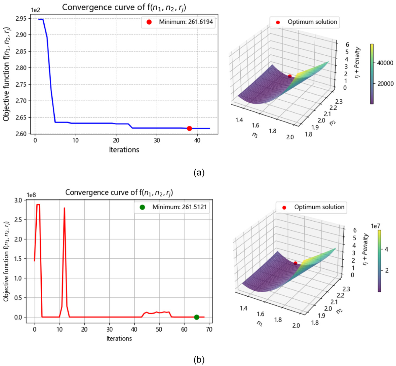
Comparison results of single objective optimization using: (a) DE and (b) SLSQP.
Optimized design values and constraints check between DE and SLSQP.
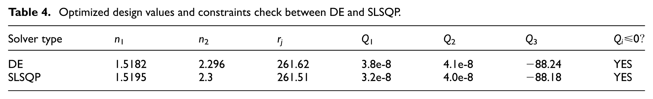
It can be concluded that the gradient-based algorithm SLSQP produced optimization results very similar to those obtained using the DE method. This observation verifies both the feasibility and the effectiveness of employing DE for solving the single-objective optimization problem. The agreement between the two methods demonstrates that DE is capable of achieving high-quality solutions comparable to a well-established gradient-based approach, while offering additional flexibility in handling nonlinearity and complex constraint landscapes.
Multi-objective optimization of both cylinder weight and wires count
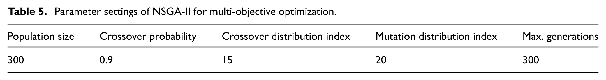
This case study is to optimize the same HIP prototype in section “Single-objective optimization of the cylinder weight,” while with different objective of reducing both cylinder weight and wires count based on the same principle demonstrated in section “Optimizing both cylinder weight and wire layer count.” The settings of NSGA-II parameters are listed in Table 5.
Parameter settings of NSGA-II for multi-objective optimization.
The optimization result is shown in Figure 4, with solutions at the Pareto front highlighted.

Optimized trade-off results between cylinder weight and wires count.
Most of the solutions on the Pareto front exhibit parameter values where n1 falls within the range of 1.47–1.51, and n2 ranges from 2.08 to 2.26. Additionally, the radius r j remains approximately constant at around 262 mm across all solutions.
To further evaluate the trade-off characteristics, several representative solutions from the Pareto front are selected and compared with the optimal solution obtained in section “Single-objective optimization of the cylinder weight.” The comparison results are summarized in Table 6.
Comparison of the results obtained by single and multi-objective optimizations.

It can be observed that the cylinder thickness obtained through multi-objective optimization does not differ significantly from that derived using single-objective optimization. However, the number of wire layers is notably reduced. This trend becomes more pronounced in large-scale HIP cylinder optimization problems.
As an illustrative example, Figure 5 and Table 8 present the optimization results for an ultra-large scale HIP cylinder with design parameters shown in Table 7.

Single and multi-objective optimizations of the ultra-large HIP cylinder: (a) optimization result of cylinder weight using DE and (b) Pareto optimal results of cylinder weight and wires count using NSGA-II.
Design parameters of the ultra-large scale HIP cylinder.

Comparison of optimization results of the ultra-large HIP cylinder.

It can be seen that for this ultra-large HIP cylinder, the multi-objective optimization yields a design with only a 6 mm increase in cylinder thickness compared to the result obtained from single-objective optimization, while achieving a 37.5 mm reduction in total wire thickness. In such large-scale constructions, this reduction corresponds to a saving of over 450 km of wire length, which is highly significant in terms of material and cost. According to the aforementioned findings from the multi-objective optimization, it is recommended to select a solution from the Pareto front according to engineering priorities. Specifically, when an increase in cylinder thickness is within 10 mm and leads to a reduction of more than 10% in wire consumption compared to the single-objective optimization result, such a solution can be adopted for practical applications, particularly in large-scale HIP constructions.
Based on the above findings, the following summary can be drawn:
Single-objective optimization is suitable for general HIP cylinder design, especially when the primary goal is to minimize cylinder weight. However, as the scale of the HIP cylinder increases (such as for working diameters exceeding 2000 mm), the consumption of prestress wires becomes a non-negligible factor. In these cases, multi-objective optimization proves more effective by enabling a balanced trade-off between cylinder weight and wire usage, thereby reducing the overall manufacturing costs of both the forging and winding materials.
FEA verification of the optimal HIP cylinder design
The optimum design obtained in Table 6, based on multi-objective optimization results, is used for FEA to verify its feasibility in engineering application. For this case,
Static stress analysis of wire-wound cylinder
The actual r j and r o values are determined according to equations (6) and (7), which are respectively 262 and 332.5 mm. The winding stress curve as demonstrated by Yan and Gronbaek based on constant shear stress principle, is shown as follow10,11:
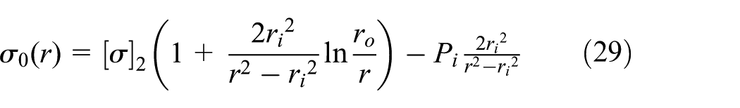
It should be noted that a continuously varying winding stress distribution is not feasible in practical engineering applications. Instead, an equivalent layer-by-layer winding process with constant tensile stress per layer is employed. Assuming that the total number of wound wire layers is Z o , the cumulative prestress exerted on the cylinder is obtained by the superposition of the individual prestress contributions from each wire layer. To satisfy the design criteria, the total prestress should be expressed as:
Where r k is the inner radius and rk+1 is the outer radius of the k th wire layer.
Thermal stress method (TSM) can be used to simulate the behavior of wire subjected to uniform tensile winding stress. TSM is based on the compatibility of deformation resulted by thermal contraction. To more accurately simulate the actual winding process, the equivalent temperature difference ΔT is derived in this study by explicitly considering the effect of finite wire layer thickness. During the winding of the k th wire layer, the deformation relationship is shown as:

Where

Substituting equation (32) into equation (31), the equivalent temperature difference can be derived:

Thus, the winding stress of each wire layer and the corresponding temperature difference can be determined.
Note that in the early stage of wire-winding technology development, it was not feasible to achieve and control layer-by-layer winding stress adjustment (i.e. variable-tension winding). Therefore, an alternative approach was adopted: the winding layers were divided into several steps, and a constant winding stress was applied within each step. Extensive experiments and engineering practice have verified the feasibility and reliability of this equivalent approach.32–34 This provides guidance for finite element modeling, where a similar simplification can be employed to significantly reduce computational cost while maintaining nearly the same level of accuracy.
Based on engineering experience, when the thickness of each simplified winding step is less than 10% of the total wire package thickness, the step division is considered sufficiently fine, making this simplification applicable for numerical simulation. Therefore, the number of wire layers is reduced to

Using 10-layer step winding to replace continuous winding.
Assuming that the initial temperature is 0, the winding stresses as well as the temperatures of each wire layer are calculated in Table 9.

The equivalent temperatures are sequentially applied to the corresponding wire layers using the element birth and death technique. 18 Initially, all wire elements are deactivated (“killed”), and then reactivated (“born”) layer by layer in the desired winding sequence. This approach effectively replicates the engineering process of layer-by-layer wire winding within the finite element analysis (FEA) framework. The FEA procedure utilizing the element birth and death technique is illustrated in Figure 7.

FEA process of wire winding by using element birth and death technique.
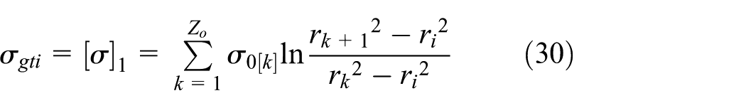
A 1/4-scale two-dimensional symmetric wire-wound cylinder model is used for FEA based on plane stress assumption. Linear elements are employed to avoid excessive deformation, and a radial network–like mesh is generated to ensure proper alignment between adjacent layers, as illustrated in Figure 8(a). In addition, each wire layer is subdivided into four slices to more accurately capture the stress gradient. Frictionless supports are applied along the symmetric boundaries, as shown in Figure 8(b). The model used for static analysis contains 14,875 elements, and a mesh refinement study under prestress state is conducted to verify its effectiveness as shown in Table 10. It should be noted that the mesh sensitivity analyses for the cylinder and the wires are based on different principles. For the cylinder, being continuous and uniform, the maximum equivalent stress can be assessed directly. In contrast, for the wires, due to their discrete structure and the errors introduced by the sequential-winding approach, spurious local peaks may appear, which do not reflect the global stress state. Therefore, the average equivalent stress of the wires is evaluated instead.
(a) Mesh of the wire-wound cylinder model and (b) constraints at symmetrical boundaries.
Mesh refinement study for the model used in static analysis.

It can be seen from Table 10 that, for the cylinder sensitivity analysis, the variation in maximum equivalent stress is 0.35% from MESH 2 to MESH 1 and only 0.17% from MESH 3 to MESH 2, indicating that MESH 2 provides sufficient accuracy. For the wires, the variation is 0.50% from MESH 2 to MESH 1 and only 0.006% from MESH 3 to MESH 2, indicating that the results obtained with MESH 2 have already converged. Thus, MESH 2 is used for static analysis.
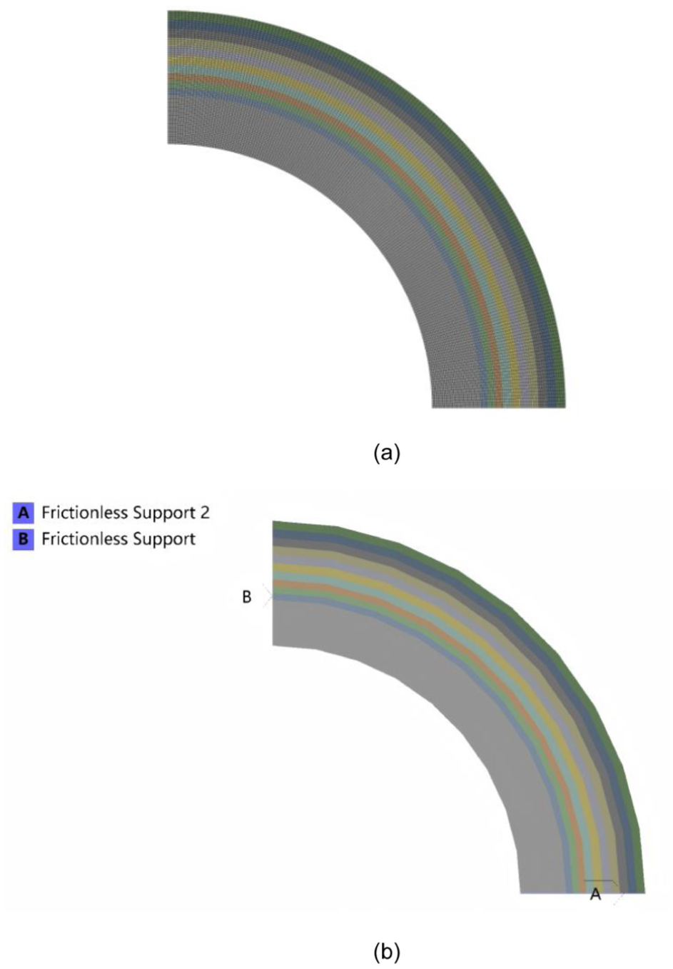
The computed FE simulation results are shown in Figure 9.
(a) Stress contour plot in prestress condition, (b) stress contour plot in working condition, (c) deformation contour plot in prestress condition, (d) deformation contour plot in working condition, (e) hoop stress distribution in prestress condition, (f) hoop stress distribution in working condition, (g) radial stress distribution in prestress condition, (h) radial stress condition in working condition, (i) deformation of inner wall radius in prestress condition.
The statistical analysis of FEA results compared to theoretical results are shown in Figure 10.

(a) Error analysis results of stress distributions in prestress condition and (b) error analysis results of stress distributions in working condition.
The FEA results show good agreement with the theoretical calculations, with most relative errors well below 15%, indicating the reliability of the simulation approach. An optional approach to improve the accuracy of the simulation is to adjust the winding stresses according to the deformation of previously wound layers. In the prestress state (Figure 9(e)), the hoop stress at the inner wall of the cylinder is close to and slightly higher than the design value. In the working state (Figure 9(f)), the hoop stress remains below zero, indicating that the cylinder stays under compressive stress during operation. Therefore, from a manufacturing feasibility perspective, the proposed design scheme is confirmed to be effective. Furthermore, the maximum equivalent stress within the cylinder is significantly lower than its yield strength, confirming that the structural integrity is maintained. Similarly, the maximum equivalent stress in the wire layers is well below the welding strength limit of 1200 MPa, demonstrating that the wires also possess sufficient strength under the given loading conditions.
It is also important to note that during the actual construction and manufacturing process, the deformation of the cylinder’s inner wall radius should be measured after each step-winding is completed under prestress condition. This measurement helps verify whether the deformation agrees with the predicted analytical value, as illustrated in Figure 9(i).
Buckling analysis of prestressed vessel
As discussed in section “Anti-buckling requirement,” the buckling behavior of the innermost vessel (excluding the water jacket) must be evaluated independently. This vessel is subjected to a uniform external pressure induced by the wound wires, calculated to be 67.05 MPa. The results of the eigenvalue buckling analysis, performed in combination with static analysis, are presented in Figure 11.

Simulation results of buckling mode shape of innermost vessel: (a) first mode shape, (b) second mode shape, (c) third mode shape, (d) fourth mode shape, (e) fifth mode shape and (f) sixth mode shape.
It can be identified that the minimum load multiplier of all mode shapes is 1.73, which is larger than the minimum anti-buckling safety factor
Thermal stress analysis
The HIP cylinder is subjected to a combination of mechanical and thermal stresses under working condition. To evaluate the resulting compound stress using FEA, a 1/8-scale three-dimensional symmetric model of the wire-wound vessel assembly is employed. The boundary conditions are consistent with the analysis performed in Section “Static stress analysis of wire-wound cylinder.” This model contains 1,568,700 elements, and the mesh refinement study is performed in Table 11.
Mesh refinement study for the model used in thermal analysis.

It can be seen from Table 11 that the maximum equivalent stress varies by 0.07% from MESH 2 to MESH 1 and only by 0.016% from MESH 3 to MESH 2, indicating that the results obtained with MESH 2 have already converged. Therefore, MESH 2 provides sufficient accuracy for use in the thermal analysis.
For simplification purposes, and according to the superposition method outlined in section “Thermal stress under steady state,” the initial prestress within the wires is neglected, and the wire–cylinder assembly is modeled as a double-layer pressure vessel with zero interference between the layers. After completing the thermal stress analysis of the simplified model, the mechanical stresses induced by the initial prestress, obtained either from theoretical calculations or from the simulation data presented in Section “Static stress analysis of wire-wound cylinder,” are superimposed onto the cylinder to evaluate the coupled thermo-mechanical strength under the actual operating condition. T i = 170°C, T j = 50°C are set as boundary conditions of the cylinder. Thermal expansion coefficient α of the cylinder is given as 14 × 106/°C. The temperatures of both the wire layers and the surrounding environment are set to 22°C. The results of the thermo-mechanical coupled simulation are presented in Figure 12. The statistical analysis of FEA results is shown in Figure 13.

FEA thermal compound stress in working state compared to theoretical results: (a) equivalent stress contour plot, (b) compound radial stress curve, (c) compound hoop stress curve, and (d) compound axial stress curve.

Error analysis results of thermal compound stress distributions.
It can be seen that FEA results are in good agreement with analytical results, with relative errors mostly below 5%. The hoop stress at the inner wall of the cylinder can be extracted in Figure 12(c), which is

Therefore, it can be concluded that the optimal HIP cylinder design obtained via penalty method is validated by the FEA results and is deemed applicable for engineering implementation.
Conclusions
This study proposed an integrated computational optimization framework for the structural design of HIP cylinders reinforced by prestressed wires. The framework combines analytical modeling, penalty-based mathematical formulation, and intelligent optimization algorithms with finite element validation. The key findings and contributions are summarized as follows:
Design methodology and governing principles: The design of HIP cylinders is guided by three essential mechanical principles: (a) equilibrium between the wire layers and the cylinder body; (b) stability of the inner pressure vessel under the prestress condition; and (c) structural integrity under working conditions considering thermal effects. These principles were analytically derived and embedded into the optimization model as constraint functions.
Optimization framework and algorithmic validation: A nonlinear optimization model was formulated using the penalty method to incorporate multiple design constraints. DE and NSGA-II algorithms were employed to handle single- and multi-objective formulations, respectively. Comparative tests with the gradient-based SLSQP algorithm confirmed that DE achieves stable convergence and robustness, demonstrating the method’s suitability for complex nonlinear optimization in engineering applications.
Single- and multi-objective design insights: The single-objective optimization effectively minimizes the structural weight while satisfying all safety requirements. Additionally, the multi-objective approach provides a set of Pareto-optimal solutions that balance cylinder thickness and wire consumption. It is revealed that a modest increase in cylinder thickness (within 10 mm) can reduce wire usage by more than 10%, offering a practical design trade-off for large-scale HIP constructions.
Numerical validation and engineering applicability: The optimized configuration defined by allowable stress levels of
Engineering significance and future perspective: The proposed framework provides a systematic, automated, and verifiable approach for the intelligent optimization of HIP cylinder design, significantly reducing reliance on empirical trial-and-error methods. Future work will focus on integrating manufacturing constraints, ratcheting and fatigue performance evaluation, and real-time optimization to further enhance the design-to-production workflow for ultra-high pressure systems.
Footnotes
Handling Editor: Aarthy Esakkiappan
Author contributions
Yubo Huang – Writing, editing, experiment, and methodology. Wen Qi – Project administration. Bao Wang – Project administration and reviewing. Zhengchi Li – Experiment and methodology. Zhoujin Lv – Project management and communication. Lei Zhang – Methodology.
Funding
The authors disclosed receipt of the following financial support for the research, authorship, and/or publication of this article: This work was supported by Ministry of Industry and Information Technology of the People’s Republic of China (Grant No. 2023ZY01010).
Declaration of conflicting interests
The authors declared no potential conflicts of interest with respect to the research, authorship, and/or publication of this article.
Data availability statement
The readers may contact the corresponding author for further implementation details and data.
Replication of results
The necessary data for replicating the results have been presented in the manuscript.