
Abstract
Fueled by global environmental policies and energy transition initiatives, new energy vehicles are undergoing rapid development. However, internal combustion engines, particularly diesel-powered vehicles, continue to dominate the global automotive market. Owing to their high energy density and extended range, diesel engines are anticipated to remain critical, long-distance transportation, and industrial machinery for a long time to come. Therefore, optimizing diesel engine systems’ emission and combustion performance is crucial for enhancing energy efficiency and reducing global pollutant emissions. This review systematically examines the influence of nozzle geometry, operating conditions, and fuel properties on in-nozzle cavitation and near-field spray atomization in diesel injectors, culminating in proposed optimization strategies.
Keywords
Introduction
Currently, new energy vehicles are developing rapidly worldwide, influenced by global environmental concerns and government policies. Nevertheless, internal combustion engines, particularly diesel-powered vehicles, maintain a dominant share of the global automotive market. 1 Despite the anticipated expansion of the new energy vehicle market, the phase-out of conventional powertrains will inevitably be a protracted process. Moreover, due to their high energy density and longer driving range, diesel engines are expected to remain indispensable in heavy vehicles, long-distance transportation, and industrial machinery for a considerable period of time. 2 Consequently, enhancing the efficiency and curtailing emissions from diesel engines through optimized combustion remain critical short-term objectives for improving global energy sustainability.
Specifically, under high load conditions, the combustion temperature must be maintained within a high range to ensure complete fuel pyrolysis and promote the conversion of nitrogen to nitrogen oxides. However, although traditional lean-burn combustion methods can improve thermal efficiency, the concentration gradient in the local air-fuel mixture may create incomplete combustion zones, which are the primary source of particulate matter emissions. To comply with increasingly stringent emission regulations, researchers have proposed various combustion strategies.3–5 The essence of these strategies is to achieve clean combustion by precisely controlling fuel injection parameters, as shown in Figure 1 (an original image created by the author).

Comparison of three combustion modes: HCCI, PCCI, and LTC.
The advent of electronically controlled high-pressure common-rail systems has been instrumental in enabling new combustion modes. The system achieves ultra-high-pressure injection through the accumulation of common rail pressure, significantly improving fuel atomization quality and combustion phase control. The core control logic of the system is managed by an electronic control unit (ECU). As a key component, the common rail ensures that fuel is evenly delivered to each cylinder’s injector under constant pressure, and the injectors achieve millimeter-level injection timing and fuel quantity control based on precise commands from the ECU, 6 as shown in Figure 2.

Schematic diagram of the common-rail injection system. 6
The fuel injector nozzle serves as the critical interface between the upstream and downstream sections of the fuel injection system, and its internal flow decisively affects the spray pattern and various performance parameters. The main components are illustrated in Figure 3 (which is an original image created by myself), and the part primarily discussed in this paper is the nozzle hole, which is shown in the enlarged image below.

Profile structure of injector nozzle.
Flow contraction and pressure gradient changes inside the orifice can readily generate various flow patterns, including cavitation and bubble ingestion, which are particularly prominent in high-pressure injection scenarios and micro-orifice configurations. The fuel flow represents a typical cavitating two-phase flow. Specifically, cavitation caused by sudden changes in nozzle geometry is termed geometry-induced cavitation, while cavitation caused by vortex formation is termed string cavitation. Figure 4 describes the two cavitation mechanisms and their respective spraying modes, highlighting the important influence of the flow dynamics on the atomization efficiency and injection stability.
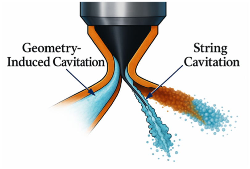
Schematic diagram of geometry-induced cavitation and string cavitation.
Cavitation phenomena in diesel injector nozzles and their characterization parameters
Overview of cavitation phenomena
In high-pressure fuel systems, diesel fuel flows at velocities reaching several 100 m/s. As the flow direction and cross-sectional area change, the local flow velocity increases significantly, leading to a sharp pressure decrease. Cavitation occurs when the local pressure falls below the fuel’s saturation vapor pressure.
Importantly, cavitation on the internal wall surface generates pressure waves from micro-jet impacts and bubble collapse, which can cause erosive damage to the nozzle material. In contrast, cavitation-induced disturbances at the outlet enhance fuel-air mixing, leading to a more homogeneous mixture. This dual role of cavitation—both detrimental and beneficial—significantly impacts nozzle longevity and combustion efficiency. 7
A distinct category of cavitation, characterized by filamentary structures, is termed string cavitation or vortex cavitation. This form of cavitation is caused by vortices formed within the nozzle flow channel, where the pressure in the core rapidly drops below the saturation vapor pressure, leading to cavitation. Unlike geometry-induced cavitation, the bubble morphology in string cavitation does not directly contact the nozzle’s inner wall, thus avoiding erosion damage.
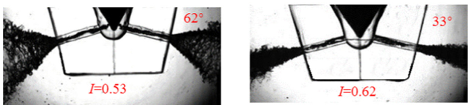
Notably, vortex cavitation (string cavitation) significantly enhances fuel atomization compared to geometry-induced cavitation (Figure 5). This occurs because the vortex structure generates a strong centrifugal force field at the nozzle outlet, leading to higher-frequency pressure disturbances during vapor bubble collapse. This micro-explosion effect, combined with the shear force generated by vortex motion, effectively promotes secondary droplet fragmentation, resulting in finer particle distribution and a more uniform spray field.

The string cavitating patterns in injector nozzle.
Characterization parameters of cavitation phenomena
The flow inside the nozzle is a complex multiphase turbulent process, involving the interaction of liquid, vapor, and entrained gas. Fluids, encompassing both gases and liquids, possess inherent properties (density, viscosity, surface tension, thermal conductivity, and mass diffusivity) that are functions of temperature, pressure, and composition. Fuel, as a typical fluid medium, exhibits different flow characteristics under specific operating conditions of diesel engine injectors. Its flow pattern can be categorized as laminar or turbulent based on flow state, steady or unsteady based on temporal characteristics, and single-phase or multiphase based on phase composition.
In fluid mechanics, flow similarity between systems is achieved when they share proportional dimensions, initial/boundary conditions, and dynamic forcing mechanisms. This similarity is quantified using specific criteria, primarily dimensionless parameters. By eliminating scale effects, these parameters reflect the inherent consistency of flow characteristics within the system. Establishing fluid system similarity requires satisfying multiple matching criteria simultaneously, including geometric configuration, kinematic characteristics (such as velocity distribution), and dynamic parameters (such as force ratio). The dimensionless group is a mathematical expression that normalizes and couples these multidimensional physical quantities.
Reynolds number
The Reynolds number (Re) characterizes the transition from laminar to turbulent flow. Re represents the ratio of inertial forces to viscous forces and is defined as follows:

Here, U represents the characteristic velocity, and L represents the characteristic length, which depends primarily on the fluid flow apparatus. ρ denotes the fluid density, while μ and υ represent the dynamic viscosity and kinematic viscosity of the fluid, respectively.
The flow regime is determined by the Reynolds number (Re). At low Re, viscous forces dominate, resulting in laminar flow. In this regime, the flow velocity is very low, and fluid particles move along parallel paths without mass exchange between layers. When Re increases sufficiently for inertial effects to dominate, the flow transitions to turbulence (also known as turbulent or chaotic flow). In this regime, the flow velocity increases significantly, and streamlines mix, forming a multi-scale vortex structure. The flow state between laminar and turbulent is defined as transitional flow.
Cavitation number
The cavitation number (CN) is a key dimensionless parameter governing cavitation inception and intensity. It physically represents the balance between the injection pressure (Pinj), backpressure (Pback), and the vapor pressure (Pvap). It is defined by the following mathematical expression:

This equation balances the pressure-driven cavitation effect against the fluid’s dynamic resistance. The numerator represents the effective pressure gradient, while the denominator reflects the influence of viscosity and flow velocity. A lower cavitation number increases the propensity for cavitation inception. An increase in injection pressure (Pinj) leads to a higher cavitation number; conversely, a decrease in backpressure (Pback) results in a significant increase in the cavitation number. Under normal operating conditions, Psat is typically much lower than P2; thus, its effect on the cavitation number is often negligible at constant system pressure. Consequently, the cavitation number is primarily determined by the difference between the injection pressure and the backpressure.
Discharge coefficient
The discharge coefficient (C d ) is a key parameter for characterizing the flow performance of a nozzle. The discharge coefficient (C d ) is defined by the following equation:

The discharge coefficient is strongly correlated with the internal cavitating flow behavior, and its value decreases with increasing cavitation intensity. This equation is applicable only under cavitating flow conditions. Numerous studies have investigated and validated this correlation, which will be discussed in detail in subsequent sections. As shown in Figure 6, the discharge coefficient remains constant for a given liquid under non-cavitating conditions. Upon cavitation inception, the discharge coefficient decreases predictably with the cavitation number. 8

Coefficient of discharge with cavitation number in diesel nozzle. 8
Generally speaking, researchers can induce different cavitation morphology distributions by systematically adjusting the design parameters of the nozzle structure (such as aspect ratio, cone angle, nozzle shape, inlet angle, and SAC volume). A consistent finding is that using a convergent nozzle structure can effectively suppress cavitation caused by geometric features, while significantly enhancing the vortex driven cavitation effect.
In addition to geometric factors, the physical properties of fuel are also significantly affected, among which the mechanism of temperature parameters and component composition on the development of cavitation is a focus of attention. In the field of dynamic operating parameters, boundary conditions such as injection pressure, back pressure, and injection duration have become current research hotspots. The coupling effect of different parameter combinations in the cavitation modulation process was systematically verified on different types of experimental platforms, revealing several flow control laws with guiding value. The exploration of these multidimensional parameter spaces has laid an important foundation for establishing the quantitative relationship between cavitation morphology and spray characteristics.
In addition, enhancing the understanding of internal flow and atomization of nozzles through cavitation research can significantly improve the fuel air mixing process, reduce fuel consumption, and support compliance with strict emission standards (such as Euro 7, China VI, and US EPA Tier 4). Therefore, the study of cavitation phenomenon not only has scientific value, but also has strategic importance in the transition to environmentally sustainable transportation.
Influence of key factors on cavitation and near-field spray in diesel injector nozzles
Geometric structural factors
Nozzle geometry is a fundamental factor influencing cavitation inception and development. Due to their ease of fabrication, early studies often empirically investigated nozzle geometry effects, focusing on orifice plate shapes and pressure chamber properties. Subsequently, with advancements in numerical modeling, research in this area expanded to include computational fluid dynamics (CFD) simulation.
Cavitation test benches, like most experimental setups, have evolved from simple to complex designs. Among these, the two-dimensional planar nozzle rig is the simplest to construct. Consequently, early cavitation experiments were primarily conducted using such setups. Due to the structural characteristics of two-dimensional flat plates (where the nozzle inlet transition is simplified to a more abrupt two-dimensional form), the onset of cavitation and cloud cavitation phenomena are easily observable. For example, high-resolution imaging of transient cavitation in rectangular nozzles has been used to validate combined models against simulations. 9 Figure 7 shows the comparison between the combined model and experimental results. Unfortunately, no upgraded version of the model was proposed in subsequent research. After the onset of cavitation, by changing the liquid flow velocity and fluid properties, the sheet-like cavitation can become unstable, which makes it relatively easy to observe the detachment phenomenon at the tail of the sheet-like cavitation, known as cloud cavitation. Research has shown that the dynamic process of cloud cavitation shedding is influenced by a mixture of vortex shedding and pressure oscillation. 10 By analyzing the quantitative images of visualization experiments, the frequency of cloud cavitation and detachment can be accurately predicted using large eddy simulation methods. Cloud cavitation occurring at different locations has different impacts. The closed zone of the steam cloud diffuses downstream in a transient manner with obvious periodicity, characterized by the Strouhal number. 11 When cloud cavitation occurs at the nozzle hole outlet, the resulting turbulence disturbance is one of the important factors leading to the formation of the filamentous ligament around the spray, 12 as shown in Figure 8. From the perspective of fluid velocity, research on the periodic detachment of cloud cavitation shows that when a specific inlet velocity threshold is exceeded, the detachment of laminar cloud cavitation reaches a consistent periodic pattern, as shown in Figure 9. In addition, as the inlet flow velocity increases, the recovery frequency of the tail region of the sheet-like cavitation is negatively correlated with the inlet flow velocity, which is also reflected in the relevant Strouhal number. 13 The occurrence and development of cavitation, including cloud cavitation, have been determined to be influenced by flow velocity and not by aspect ratio or needle tip position. 14 Of course, if the needle valve tip is not aligned, the cavitation inside each nozzle hole will exhibit significant asymmetric development. In addition, some researchers have used numerical simulation techniques to investigate the instability of cavitation detachment from the perspective of re-entry jets, and have obtained a strong correlation between simulation results and experimental observations. 15

Comparison between experimental data and simulated data of cavitating flow. 9

Morphology of super cavitation and spray field. 12

Pressure fluctuations (cloud shedding). 13
It is worth noting that there is little research on the cavitation characteristics of pipe columns on a two-dimensional flat plate cavitation test bench. There are two reasons for this phenomenon: firstly, the two-dimensional flat plate cavitation test bench appeared earlier, and the research on cavitation phenomenon is still in its infancy, and the phenomenon of pipe column cavitation has not yet been discovered. Secondly, due to the structural characteristics of two-dimensional flat plates, it is difficult to form a strong vortex flow state, which does not meet the initial conditions for series cavitation.
Quantitative temperature variation experiments demonstrate that raising the fuel temperature from 25°C to 60°C leads to a 20% increase in cavitation inception area (from 2.5 to 3 mm2) at the nozzle hole entrance, as measured by synchronized high-speed camera and pressure transducer systems. This thermal effect is consistent across different fuel types, including diesel and methanol, with methanol exhibiting a slightly higher sensitivity (22% increase in cavitation area under identical conditions). Furthermore, the enhanced cavitation activity correlates with improved spray atomization, evidenced by a 9% increase in spray tip velocity (from 80 to 87.2 m/s) and a 6% reduction in droplet size (SMD decreased from 24 to 22.56 μm), measured by particle image velocimetry (PIV) and laser diffraction techniques, respectively, 16 as shown in Figure 10. Different fuel media correspond to different spray shafts. Compared with biodiesel and diesel, biodiesel has higher surface tension and viscosity (lower surface instability), and its spray angle narrows. 17

The contour of vapor volume fraction of geometry-induced cavitation. 16
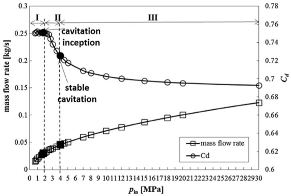
Due to its large-scale nature, the details of transient cavitation development inside the enlarged transparent nozzle have always been easily captured. 18 Therefore, researchers often use such test benches to study the transient flow characteristics of cavitation. Unlike the two-dimensional flat plate cavitation test bench, the columnar cavitation phenomenon is particularly evident in the enlarged cavitation test bench. Of course, cloud cavitation can still be observed in the enlarged nozzle holes. However, in this case, cloud cavitation does not dominate; Instead, string cavitation occurs. In addition, we also observed that under the influence of pressure difference, 19 cloud cavitation detached from the tail of the sheet-like cavitation can migrate to the columnar cavitation region, 20 as shown in Figure 11. The coexistence of cloud like cavitation and columnar cavitation in nozzle holes is not common; Usually, under the action of strong eddy currents, there is only one form of cavitation inside the nozzle hole (series cavitation). In this case, as the cavitation intensity increases, the cone angle related to the cavitation of the cylindrical tube also widens. This can be clearly seen by comparing the cone angles of the pipe column cavitation generated by the conical surface of the needle valve and the wellbore cavitation. However, when considering the pressure fluctuations caused by cavitation, a higher cavitation intensity may not necessarily be advantageous. The main reason for these pressure fluctuations is the change in the effective cross-sectional area of the nozzle hole, which is influenced by the intensity of vortex cavitation. This reflects temporary changes rather than sustained cavitation intensity. As shown in Figure 12, although the cavitation intensity caused by needle valve lifting is lower than that caused by needle valve lifting under the same conditions, the pressure change caused is more significant. In addition to affecting pressure fluctuations, changes in cavitation intensity can also be measured using another metric: flow coefficient. In the initial stage of cavitation, as the cavitation intensity increases, the flow coefficient slightly increases and then sharply decreases. Therefore, the inflection point of the flow coefficient can serve as an indicator for detecting the onset of cavitation, as shown in Figure 13. Among them, Kcrit is the starting point of cavitation. In addition, similar to geometric induced cavitation, due to the asymmetry of fuel flow, string cavitation is also sensitive to needle valve eccentricity, resulting in differences in vortex intensity in different nozzle holes.
Two special cavitation patterns (needle-originated string cavitation and hole-to-hole string cavitation) were observed simultaneously. 19

Pressure pulsation trends corresponding to needle-originated string cavitation and hole-to-hole string cavitation. 19

Correlation between K and Cd for nozzles with different length–diameter ratios. 20
The type of nozzle hole significantly influences cavitation morphology. Quantitative analysis reveals that, compared to straight hole nozzles, convergent nozzles reduce geometry-induced cavitation area by approximately 3% at low needle lifts, as evidenced by high-speed camera observations. Simultaneously, they enhance cavitation intensity by 4%, leading to a 5.2% increase in spray breakup rate. 21 Geometric induced cavitation usually occurs in divergent nozzles, and under the same conditions, the conditions for generating geometric induced cavitation in straight hole nozzles are relatively strict. In addition, compared with the other two hole shapes, 22 convergent nozzles have higher flow stability and better emission performance under the same outlet diameter. The researchers also studied another type of hole type-spiral groove (adding spiral grooves inside the nozzle hole). Research has found that this type of hole significantly inhibits the onset of cavitation. Focusing on the nozzle hole outlet, it can be observed that the spray cone angle of the spiral slot hole is 4–7 times larger than that of the ordinary hole, which fully reflects the positive role of this hole in enhancing spray atomization, 23 as shown in Figure 14. In shadow imaging mode, when there is cavitation in the drill string inside the hole, excess shadow areas often appear at the hole outlet. Initially, researchers were unsure whether these additional shadow areas were caused by air being sucked back into the nozzle inlet. It was not until the researchers completed the underwater jet experiment and combined it with the simulation of the three component multiphase model that they discovered that the shaded area at the outlet of the hole was caused by the inhalation of air or steam due to the phase transition of columnar cavitation. 24

The near-field jet of the NSH, SGH63, and SGH43 nozzles. 23
It is worth noting that although the enlarged transparent nozzle has very similar flow characteristics to the prototype nozzle, they are only similar rather than completely identical. Although the macroscopic cavitation structure can be defined by the cavitation intensity, the transient development of cavitation bubbles inside the nozzle varies at different scales due to the different residence times and lifetimes of moving bubbles. However, based on the similarity of flow between nozzles of different scales and extensive research experience on the cavitation flow characteristics inside enlarged holes, a deeper and more comprehensive understanding of the cavitation flow characteristics inside actual sized nozzles under actual operating conditions of diesel engines has been obtained. 25
Considering the small structural size and opacity of actual metal nozzles, some researchers choose to use synchrotron X-ray phase contrast imaging technology to study the cavitation flow characteristics inside these nozzles. However, in terms of effectiveness and convenience, this method ultimately falls short of transparent nozzles. However, in the study of metal nozzles, researchers found a new near hole spray atomization form, namely mushroom nozzles. Initially, researchers observed a mushroom shaped nozzle in the experiment and subsequently established a model to validate and expand the experimental results. This study only speculates that this injection structure may be caused by air entering the nozzle after the needle valve at the end of the previous injection was closed, but does not analyze the specific reasons in detail, 26 as shown in Figure 15. Subsequently, other researchers conducted further research and determined that mushroom shaped nozzles can exhibit different shapes based on the presence of bubbles. For example, the direct cause of thin mushroom nozzles is the bursting of bubbles in spray. The thrust generated by bubble rupture, combined with surface tension and air resistance, causes the compact mushroom shaped nozzle to deform. If there are multiple bubbles in the spray, the energy released by the compressed bubbles can produce a drum plume, 27 as shown in Figure 16. The position of the bubbles inside the nozzle hole is also crucial. Bubbles reach maximum compression away from the nozzle outlet, but when they approach the needle valve at the outlet, due to the decrease in flow velocity difference, the bubbles expand, resulting in reduced compression and energy storage. Nevertheless, the residual energy is still sufficient to support the spray atomization in the area of the hole outlet. 28 The mushroom shaped spray head is usually surrounded by ligaments. The formation of ligaments is relatively complex and can be summarized as the shear action of local vortices. Under this shear action, the tip surface of the mushroom shaped nozzle undergoes vortex motion, resulting in the formation of two types of ligaments near it: quasi axisymmetric ligaments and downstream ligaments. Ligaments were also observed on the surface of the liquid nucleus, which were formed by spinal fractures caused by surface instability, 29 as shown in Figure 17.
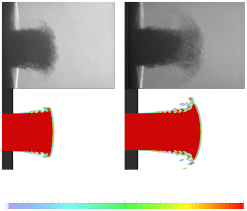
A good correspondence between the mushroom head shapes determined in experimental and simulated environments. 26
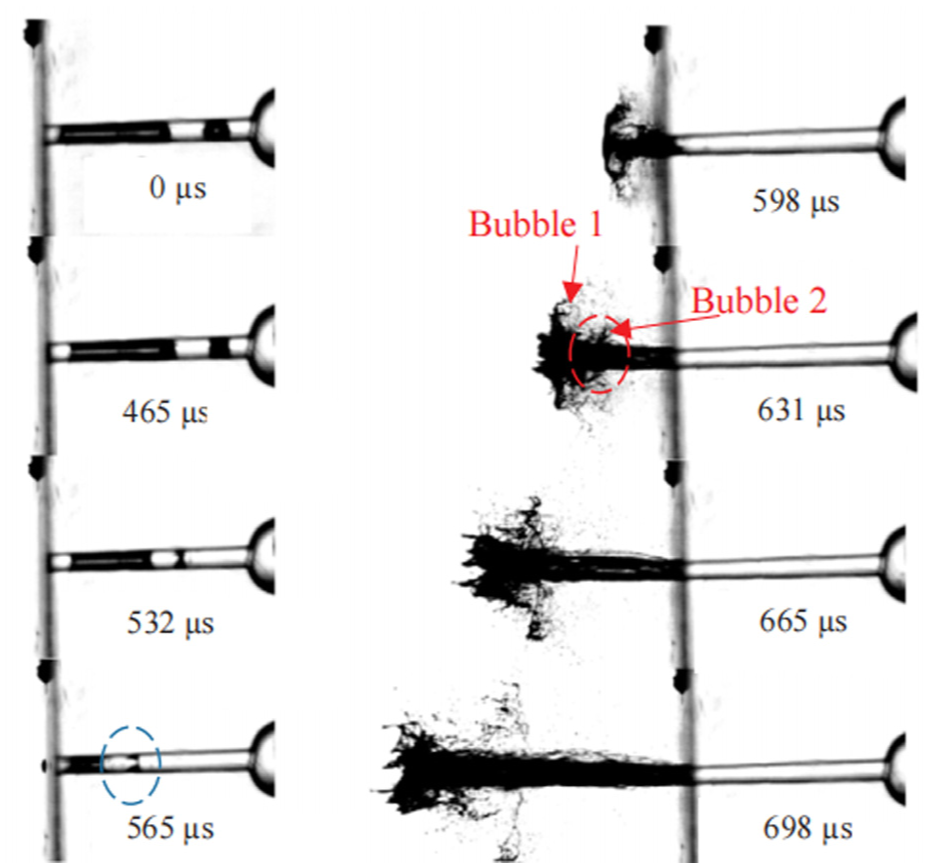
The drum shaped plum produced by multiple gas bubbles. 27

Ligament formation of the fuel spray. 29
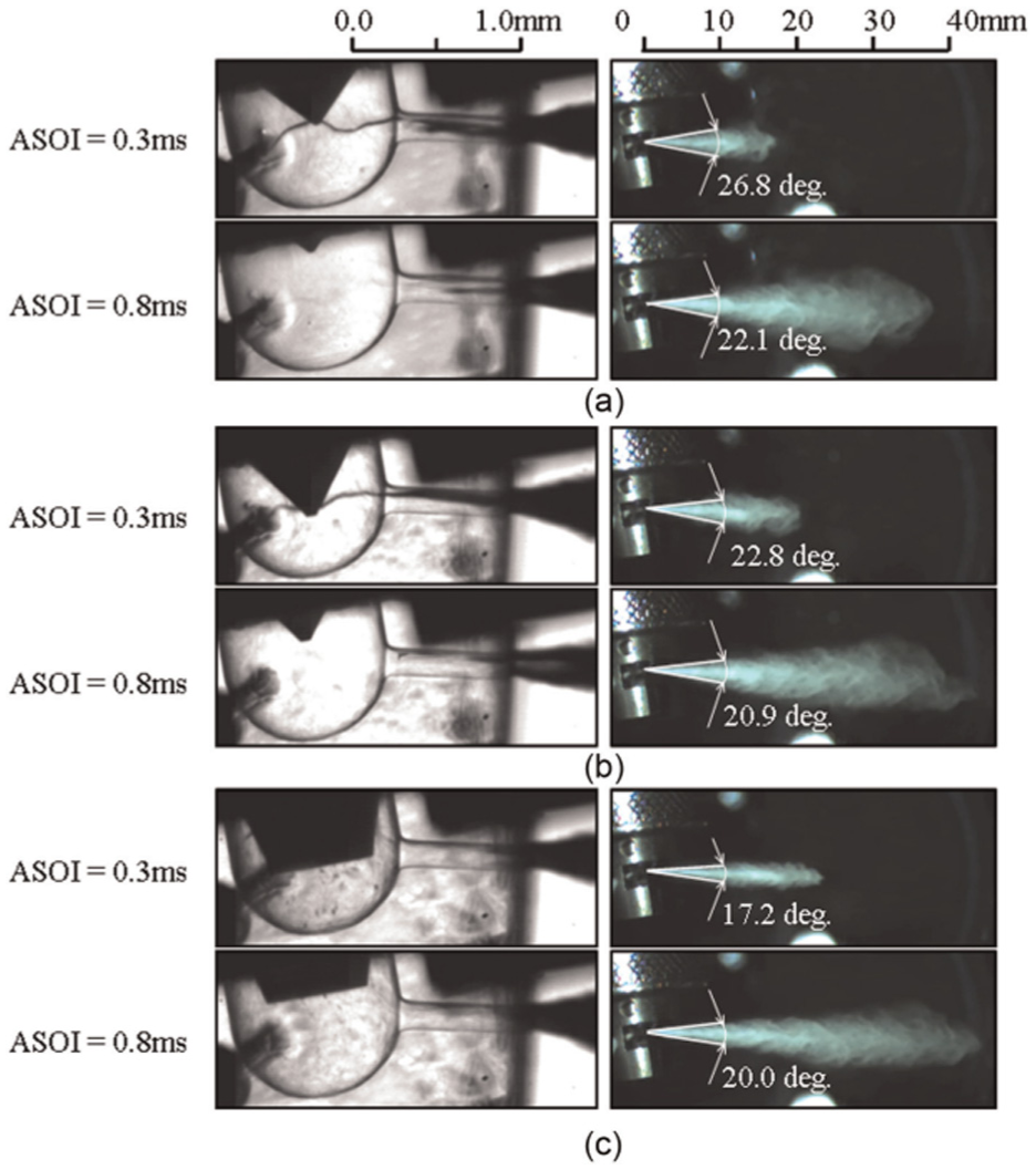
Sometimes, vortex motion does not necessarily lead to the formation of ligaments. However, it inevitably brings ambient gas into the spray area, which is called ambient gas entrainment. This can be clearly observed through the micro PIV technology. It is found that the gas entrainment rate is linearly related to the axial distance of the spray, and the fracture dynamics of the spray center plays a leading role in determining the entrainment rate.30,31 In addition, single and multiple exposure X-ray phase contrast images can be used to characterize ligaments and capture specific aspects such as jet rupture and droplet splashing during transient processes. During the characterization process, it was observed that small and circular ligaments were formed under conditions of fewer pores and shorter pore lengths. Specifically, after fuel enters each hole from the SAC chamber, the shorter the hole, the faster the fuel velocity decreases, and the higher the degree of fragmentation of the corresponding injection pattern, as shown in Figure 18. This spray pattern usually shows a large spray cone angle, but due to the loss of early protection of the hole wall, it may be affected by changes in the density of the spray environment.32,33 Similarly, the more holes there are, the faster the fuel velocity decreases in both axial and radial directions, which slows down the intensity of jet rupture. 34 Meanwhile, the more holes there are, the more uniform the distribution of upstream working pressure 35 becomes. Of course, having more holes is not always better. For example, in the simulation study of 3–9 holes, researchers observed that the jet went from highly dispersed and fluctuating to stable, and then to strong turbulent fluctuations, corresponding to 3–7, 8, and larger than eight holes, respectively. 36 After the number of holes is determined, the arrangement between holes is also a topic worth studying, and the angle between holes is an important parameter. Compared with the single hole nozzle, the proper hole angle can enhance the near-field spray atomization effect and make the spray droplets smaller. But when the angle is small and the distance between the holes is close, under the influence of negative relative pressure, the corresponding jets will interact with each other, causing the jet axis to deflect, 37 as shown in Figure 19. However, this deflection phenomenon is relative; In reality, even if the jet undergoes slight deflection, the main body of the jet remains roughly within the axial region of the hole and maintains the integrity of the jet core, even at high jet pressures. 38 More creatively, researchers have proposed a new type of V-shaped cross hole diesel engine nozzle. In the experimental study of phase Doppler wind speed measurement, fuel droplets with smaller diameter were detected, and the fan-shaped spray structure was captured. Compared with the conventional conical spray, the penetration of the fan-shaped spray structure at the spray tip is weaker, but the spray angle increases. The angle of the v-shaped hole can control the spray angle characteristics of the front and side, 39 as shown in Figure 20. In a real nozzle, although the internal cavitation inside the hole cannot be directly observed, the near hole spray morphology characteristics can provide insights into the situation. For example, the fracture mode, fuel jet deflection and asymmetric velocity behavior of spray from different holes may be caused by different cavitation patterns in the holes due to the irregularity at the nozzle inlet. 40 By combining an amplified dual pulse laser source with a dual frame camera in the experiment, the asymmetry of the jet can also be obtained. In this setup, it is possible to clearly capture different high-speed and low-speed regions on both sides of different holes. It is even possible to obtain a specific speed difference—the speed difference between the “high speed” and “low speed” sides of the spray is about 100 m/s, thus producing a difference in the spray atomization environment. 41 For the regular inlet nozzle, compared with the sharp inlet nozzle, the spray produced by the smooth inlet nozzle has a larger radial diffusion range and a shorter axial spray distance in the near hole area. As the jet moves toward the far field area, the spray growth rate of the smooth inlet nozzle increases rapidly, almost reaching the growth rate level of the sharp edge inlet nozzle, but the radial diffusion width remains in a small range. 42 This result is similar to the situation of jet flow during hydraulic flipping. Specifically, when cavitation develops to the outlet of the hole, it causes hydraulic overturning, resulting in an extension of the jet rupture length.43,44

Effect of nozzle length on spray velocity and spray cone angle. 32

Asymmetric structure of spray in group hole puzzle. 37

Comparison of spray angles of front-face and side-face sprays in the V-shaped nozzle. 39
Similar to the enlarged transparent nozzle, various types of column cavitation phenomena are often observed in the prototype transparent nozzle, highlighting the commonality of column cavitation morphology.
In fact, it can be inferred that columnar cavitation patterns also exist in real metal nozzles. However, due to limitations in actual detection methods, they are rarely mentioned in experiments with real nozzles, although this does not mean that there are no such studies published. For example, researchers added 1 μm sized tungsten particles to diesel in the laboratory, enabling them to record relevant X-ray images using high-energy multi-color X-rays. The study successfully revealed the transient behavior of vortices, vortex induced cavitation, and flow separation in steel micro nozzles, 45 as shown in Figure 21. Under the conditions of the prototype nozzle, the presence of vortices inevitably accompanies the cavitation of the string. The experimental results show that as the needle valve head increases, the cavitation intensity of the pipe column first increases and then decreases. One possible explanation for this trend is the change in kinetic energy of fuel flow. X-ray tracing imaging has revealed for the first time the transient vortex and cavitation phenomena that occur in real high-pressure injection scenarios. In addition, the similarity between the jet and outflow characteristics inside the nozzle was confirmed by comparing with the experimental results of enlarging the nozzle under the same conditions. Due to the high manufacturing complexity and precision requirements of various types of experimental nozzles, simulation methods can be used to assist in the study of complex hole types. For example, in the study of elliptical nozzles, some researchers have employed numerical simulation methods. Four elliptical holes were selected, distinguished by their main axis orientation (vertical or horizontal) and eccentric horizontal changes, while maintaining the cross-sectional area of the hole outlet as the sole control parameter. As shown in Figure 22, the research results indicate that under the same injection conditions, there are significant differences in the occurrence and spatial distribution of critical cavitation among different nozzle designs.The elliptical nozzle with a horizontal long axis direction experiences cavitation earlier, and its cavitation trend is similar to that of a circular nozzle.

The influence of needle lift on the fluid dynamics within the nozzle. 45

Contour representation of vapor mass fraction. 46
The cavitation conditions of elliptical nozzles with a vertical axis are more stringent. Compared with cylindrical nozzles, horizontally arranged elliptical nozzles exhibit remarkably similar cavitation patterns, characterized by steam formation adhering to the upper wall of the aperture in both nozzle designs. On the contrary, vertically oriented elliptical nozzles are prone to forming cavitation structures, which tend to propagate toward the central area of the hole, as shown in reference. 46 From the morphology of cavitation, the cavitation inside the cylindrical nozzle is cylindrical and symmetrical around the hole axis. Due to the larger range of cavitation along the long axis surface compared to the small axis surface, the cavitation shape inside the elliptical nozzle presents a horseshoe shape. 47 In addition, compared with the circular nozzle, the elliptical nozzle has better spray distribution and droplet crushing effect.48–50
Multiple studies have shown that the pore shape has a significant impact on the cavitation flow pattern inside the pore. In the comparative study of cylindrical and conical nozzles, it was found that cylindrical nozzles can simultaneously accommodate geometrically induced cavitation and columnar cavitation, while conical nozzles suppress geometrically induced cavitation and only allow columnar cavitation to occur. In a cylindrical nozzle, when two types of cavitation coexist, geometrically induced cavitation gathers near the hole axis under the influence of vortices and columnar cavitation. The aggregation of geometrically induced cavitation also plays a role in obtaining wider jet cone angles, as described in. 51 As shown in Figure 23, at 1500 µs, when the geometrically induced cavitation phenomenon does not gather near the hole axis, the spray cone angle is still very narrow. But the cone angle increased significantly by 1500 µs, and geometric cavitation phenomena gathered near the hole axis. The upstream region of the orifice entrance, especially the SAC chamber, is crucial as it is the initial formation area of vortices. In addition to the commonly encountered cavitation caused by drilling needle lifting, another form has also been discovered, which is wellbore to wellbore cavitation, 52 as shown in Figure 24. Similar conclusions were drawn from numerical simulation studies based on Reynolds stress turbulence model and Schnerr Sauer cavitation model. In addition, the research focuses on the velocity components along the axial, radial, and tangential directions to elucidate the flow field characteristics during the cavitation process of the pipe column. A pair of co rotating vortices were discovered in the SAC chamber, which is believed to be the reason for the complex orientation of the string cavitation structure. From the perspective of the vorticity transport equation, the vortex stretching term is the main factor affecting the evolution of string cavitation, while the expansion term related to fluid compressibility has a relatively small impact. 53

The transient behavior of cavitating flow within a single cylindrical nozzle featuring a miniature sac. 51

Transient changes of hole-to-hole string cavitation. 52
For two cylindrical nozzles with the same outlet diameter, the cavitation position also shows differences. In the case of VCO nozzle, cavitation only occurs at the upper part of the hole inlet. For micro encapsulated nozzles, cavitation occurs simultaneously in the upper and lower parts of the hole inlet. Compared with microcapsule nozzles, VCO nozzles maintain lower momentum flux, which is improved under strong cavitation conditions. 54 The VCO nozzle only exhibits cavitation in the upper part, while the microcapsule nozzle exhibits cavitation throughout the entire inlet section. 54 When spiral arc-shaped grooves are engraved on the wall of the circular hole, under the guidance of these grooves, the fuel will flow in a spiral shape inside the hole, providing greater centrifugal force when the fuel jet leaves the nozzle. This leads to the generation of more ligaments and finer droplets near the pores due to strong disturbance effects, theoretically enhancing the atomization effect at the expense of sacrificing velocity coefficient and flow coefficient. 55 This is consistent with some previous research results on magnifying transparent spiral nozzles 23 and mutually confirms them. As shown in Figures 25 and 26, under the same conditions, the spray cone angle of spiral groove (SGH) nozzle is larger, but the flow coefficient is smaller.

Spray characteristics corresponding to the NSH and SGH nozzles. 56

The flow coefficients for the SGH nozzle and the NSH nozzle. 56
Even without such spiral arc groove, cavitation can still promote spray atomization. 56 Nowadays, through continuous improvement and research, the simulation method of circular holes has become more complex and accurate. Especially with the increasing popularity of the OpenFOAM open-source program, researchers have proposed an improved model that considers non-uniform bubble nucleation, mass transfer source terms caused by cavitation, diesel engine resistance, virtual mass force, and surface tension. This model effectively describes the complexity of flow and initial disintegration in diesel spray nozzles, including nozzle cavitation and nozzle fragmentation. The results indicate that the direct reason for the detachment of the cavity wall is that the evaporation zone inside the cavity is relatively small compared to the cavitation zone.
The development of jet detachment from the cavity is directly affected by Kelvin Helmholtz instability, and the deeper reason is the large velocity difference at the interface between air and fuel.57,58 This is similar to the spray characteristics obtained using the diesel spray model and the mixed limited evaporation assumption.59,60 When the cavitation conditions become more favorable, especially when the needle valve is lifted, the still attached cavitation will continue to develop along the upper surface of the hole toward the hole outlet. When the needle valve head is low, the cavitation zone mainly exists during the needle valve seat period, and the area is small, not reaching the outlet. 61 Residual bubbles were also observed in the prototype transparent nozzle. Unlike the conclusion drawn from real non transparent nozzles, the sources of residual bubbles are macroscopic observations, namely air inhalation (at the beginning of injection) and compression, as well as diesel air back suction (at the end of injection). Under the influence of residual bubbles, the morphology of near hole spray also presents mushroom structure. 62 When the jet momentum is sufficient, the ligament will be accompanied by a mushroom shaped structure. 63
Numerical modeling of cavitation has proven highly successful in recent studies. By calibrating simulation parameters against experimental metrics such as mass flow rate, momentum flux, and flow velocity, researchers can achieve close agreement between numerical results and actual flow behavior. Turbulence and vorticity are identified as the primary factors governing cavitation inception. Their influence directly causes vapor separation near the orifice inlet. Moreover, cavitation and turbulence intensity exhibit strong coupling, with peak vorticity observed at the phase interface. 64
Cavitation flow inherently involves multiphase interactions among gas, vapor, and liquid. Accurately capturing realistic flow details requires accounting for fluid compressibility, which introduces additional complexity into cavitation simulations. In response, researchers have developed an advanced compressible multiphase model combining the Volume of Fluid (VOF) method with Large Eddy Simulation (LES) within the OpenFOAM framework. This model successfully predicts cavitation initiation and development and captures the correlation between cavitation onset and a sudden increase in vorticity within the boundary layer—consistent with established literature. However, the model tends to overpredict velocity near the inner wall compared to experimental measurements, a discrepancy potentially arising from inherent flow uncertainties, numerical approximations, or experimental error. 65
Surface roughness plays a significant role in geometrically-induced cavitation but is challenging to control or measure precisely at small scales, highlighting the value of computational approaches. Numerical studies indicate that controlled roughness can enhance mass flow while suppressing cavitation, thereby improving internal flow efficiency. 66 However, non-uniform roughness distributions may lead to asymmetric cavitation and jet instability under hydraulic flip conditions, often visually manifested as spray bifurcation and inconsistency. 67
Cavitation-turbulence interaction plays a critical role in microscale flows, where slight geometric variations can significantly alter internal flow patterns—including cavitation inception, development, and collapse, as well as transitions between turbulent regimes. 68 For example, orifices with larger inlet radii exhibit higher cavitation frequency, which in turn influences spray cone angle and ignition delay. 69 Needle valve tip geometry also has a notable effect: although theoretically considered a secondary factor, it significantly influences vortex cavitation. As shown in Figure 27, Micro-PIV analysis reveals that narrower needle tip angles reduce the duration and intensity of string cavitation by suppressing vorticity near the hole, promoting stable flow, and reducing low-pressure zones and turbulent fluctuations. 70
Cavitation and spray for a variation of the needle shape with the angle of 90°, 70°, and 30°. 70
Inter-hole cavitation can be a linear cavitation phenomenon caused by weak vortices between two holes. Therefore, regardless of the influence of the needle valve tip angle or Reynolds number, its inherent stability issues exist. The external manifestation of the cavitation stability problem in the wellbore string is periodic rupture or even disappearance of cavitation. When the flow state is higher than the critical Reynolds number, repeated appearance disappearance modes can be formed within a very short 2 ms injection cycle, indicating its instability, independent of injection pressure and cavitation number. 71 Some researchers have also focused on the rupture of pipe column cavitation, using Reynolds number and cavitation number as a set of research parameters. Renault quantifies the vitality of fuel flow, and the cavitation number reflects the cavitation intensity, collectively characterizing the dynamic behavior of pipe cavitation, such as the time span and duration of rupture. The velocity field inside the cavitation column is a key indicator parameter, as shown in Figure 28. 72

(a) Identification of string disintegration and (b) the impact of flow conditions on the behavior of string disintegration. 72
Cloud cavitation, which involves cavitation instability, pressure fluctuation and spray dynamics, is a hot research topic of magnifying transparent nozzles and prototype transparent nozzles. Cloud cavitation usually occurs in cylindrical holes, and the experimental mechanism is already mature. Therefore, both experimental and simulation methods are often used simultaneously to study cloud cavitation. During cloud cavitation, significant quasi periodic pressure oscillations were observed near the cavitation zone. Therefore, this pressure change can be associated with brief transitions that occur during cloud cavitation processes. Reflux is mainly manifested at the rear edge of the attached wall cavity, flowing upstream and passing through the lower wall. The state of gas-liquid mixture remains relatively stable, so the impact on pressure fluctuations can be ignored. The pressure fluctuation effect caused by shock waves is not only strong but also persistent, 73 as shown in Figure 29. The judgment of the unstable characteristics of reflux is mainly based on two parameters: reverse pressure gradient and cavity thickness. The pressure gradient measured based on LDV indicates that the self oscillation domain of the cavitation chamber mainly depends on the average unfavorable pressure gradient, and a corresponding relationship between the unstable region and the average unfavorable pressure gradient region is established. In addition, it has been confirmed that gradients have a strong disturbance on reflux within unfavorable pressure gradients, 74 as shown in Figure 30.

Pressure instability caused by different shock waves. 73

The cavity and its spray jet under cloud cavitating instability. 74
Of course, another explanation is related to pressure waves. The cavitation of the canopy cloud continuously collapses, releasing pressure shock waves that produce periodic pulses. These pulses move upstream of the pore inlet at a speed greater than the normal flow of liquid, causing damage to the cavitation chamber. 75 The pressure shock wave is an important component of cloud cavitation collapse, and this viewpoint can be verified by coupling the fully nonlinear anisotropic uniform flow equation of single bubble dynamics. 76 Within a certain range, the collapse rate of cloud cavitation shows a linear variation and is related to the cavitation number, but not affected by the Strouhal number, 77 as shown in Figure 31. It should be emphasized that the shedding mechanism of cloud cavitation is only affected by the fluid around the cavitation cavity and is independent of the complex downstream flow field. Properly suppressing cloud cavitation can reduce fuel flow resistance and suppress cavitation noise. A simple suppression method is to place a fine obstacle on the wall and determine the position of the obstacle based on the location of cloud cavitation detachment. 78

Cloud collapse frequency at 25 mm from the axis of symmetry. 77
Dynamic factors
Dynamic factors governing cavitation flow in diesel injector nozzles primarily encompass injection pressure, backpressure, and needle valve motion characteristics. Needle valve motion typically encompasses a complete injection cycle, from its seated position to maximum lift and back to seated. During this cycle, needle valve displacement or vibration can significantly alter cavitation structures.
High-speed X-ray phase-contrast imaging reveals that a 0.05 mm increase in needle lift induces a 12% surge in cavitation volume (from 0.8 to 0.896 mm2) within the initial 2 ms, prior to abrupt collapse from pressure recovery. This transient cavitation enhances spray stability, reducing spray angle fluctuation by 15% (±5° to ±4.25°) and droplet size variability by 10% (coefficient of variation: 0.3–0.27) over a 10 ms injection event. Owing to these limitations, two-dimensional planar nozzles are primarily used in initial research stages. However, parameters such as injection pressure are still investigated using such setups. Mathematically, the relationship between injection pressure and cavitation in a two-dimensional nozzle can often be described as proportional. For instance, cavitation inception typically results from increasing injection pressure. Furthermore, cavitation development is driven by injection pressure. However, this relationship is constrained by orifice geometry and inherent system characteristics, holding only within specific cavitation regimes. Experiments show that once the cavitation extends to the orifice outlet, further increasing the injection pressure does not significantly alter the cavitation extent, which remains relatively constant. At this stage, the discharge coefficient (Cd) also stabilizes, indicating that cavitation significantly influences internal flow characteristics. 79 Figure 32 illustrates how the flow state is significantly affected by the inlet pressure. Similar to orifice length, orifice diameter exerts a comparable influence.80,81 The effect of injection pressure on the discharge coefficient varies with testing conditions and orifice geometry. Under identical injection and back-pressure conditions, the discharge coefficient decreases with increasing injection pressure for orifices of the same geometry. In this regime, the cavitation behavior differs from that described previously; the cavitation does not stabilize but gradually diminishes due to the ingestion of external gas.
Flowing characteristics of nozzle with the inlet pressure. 79
Furthermore, under the same injection pressure, the cavitation length along the major axis of an elliptical orifice exceeds that along the minor axis. 82 Different orifice geometries exhibit distinct injection characteristics under varying injection pressures. For example, sprays from elliptical orifices exhibit larger cone angles and penetration distances, which enhance their resistance to ambient pressure, 83 as shown in Figure 33. Droplet breakup intensity84,85 and breakup length 86 also increase with injection pressure. Back pressure (environmental pressure), though less frequently discussed, exerts an influence on cavitation comparable to that of injection pressure. Prior to cavitation onset, reducing backpressure increases mass flow rate. However, upon transition to supercavitation, backpressure’s influence on mass flow diminishes significantly 87 (Figure 34). Under high-pressure conditions, novel models have been developed to regulate initial cavitation bubble concentration. By studying injection pressures above 100 MPa, the applicability of the two fluid model has been expanded. Computational simulations show that the degree of cavitation in the recirculation zone near the inlet of the hole lacks response to inlet pressure fluctuations, which can be attributed to the sufficient liquid tensile strength required for cavitation bubble propagation. However, the situation is quite different in the recirculation wake, where the cavitation content may be disturbed by the interaction between shedding vortices and cavitation bubbles. 88

Spray angle and spray tip penetration for circular and elliptical holes. 83

Flowing characteristics of nozzle with the back pressure. 88
Inlet pressure fluctuations, driven by injection pressure, also play a critical role. Specifically, it is evident that in the context of pressure oscillations, the maximum amplitude of these fluctuations at the inlet of the hole increases with the increase of average injection pressure, and the inherent high-frequency pressure component is more prominent. Back pressure is opposite to injection pressure; That is to say, increasing back pressure will suppress the maximum amplitude. Research has shown that the maximum degree of pressure change is about one-tenth of the average injection pressure, which means that the impact of pressure fluctuations on cavitation mechanisms is enormous and cannot be ignored, especially in the case of cloud cavitation, due to their periodic separation patterns, 89 as shown in Figure 35. Studies indicate that elevated injection pressure advances cavitation inception and expands the cavitation zone spatially, under specified needle lift and backpressure conditions. 90 At the same time, in the initial stage of injection, as the injection pressure increases proportionally, the injection penetration length and coverage area both increase significantly. However, no trend of increasing spray angle was observed. 91

Measured pressure fluctuations at back pressure of 0.1 MPa. 89
In the enlarged transparent nozzle, with a fixed needle valve lift, as the injection pressure increases, the cavitation area first increases and then remains unchanged. In addition, a new type of cavitation phenomenon called column cavitation has been discovered under low injection pressure. A real needle valve can be installed in an enlarged transparent nozzle to study another dynamic factor parameter, namely needle valve lift. The essence of its influence on cavitation morphology lies in the blank space inside the needle valve seat and its throttling effect on fuel. Specifically, when the lifting amplitude of the needle slightly increases, the cavitation area expands. However, once the drilling needle lift is too high, the throttling effect sharply weakens, and the cavitation area rapidly degrades until it disappears from the hole again. 92 In the study of cloud cavitation, the larger gap between the needle valve seat and the valve seat has been proven to be one of the reasons for the periodic enhancement of the detachment sequence, but its impact on the main detachment frequency of the cloud cavitation sequence is relatively small. 93
String cavitation usually occurs at low needle valve lift, corresponding to the early and late stages of injection events, when the gap is small. The possible reason can be attributed to vortex circulation. In addition, the spray alignment chamber (SAC) cavity was measured by tomographic particle image velocimetry (PIV), and it was found that vortex circulation did exist in the SAC at low needle valve lift, thus generating spiral flow in the downstream hole. The vortex intensity varies with the lift of the needle valve. When the vortex intensity increases to a certain extent, string cavitation occurs. 94 During the continuous injection cycle, the phenomenon of bubble suction and compression was also observed at the beginning and end of the injection process during the drilling of the pipe column, which is the reason for the mushroom shaped near hole injection. This indicates that the phenomenon is unrelated to the cavitation morphology inside the hole and is a macroscopic phenomenon that exists in multiple injection cycles. 95 If we focus on the SAC cavity to explore the fundamental cause of string cavitation, it can be understood that the vortex inside the SAC cavity forms a low-pressure zone, followed by the appearance of cavitation strings. The low-pressure zone extends along the wellbore, ultimately forming pipe column cavitation generated by the SAC cavity. Or, the bubbles are transported to the spray area, and the SAC cavity is the necessary trace to form the observed cavitation “string.” 96
In addition to natural reciprocating motion along the axis, needle valves can also exhibit vibration and eccentricity in some special cases. These two phenomena are actually quite common and represent a dynamic process during the needle valve movement. Therefore, it is different from the research methods used by most researchers, mainly focusing on fixed needle valve elevators, which better reflects practicality and authenticity. Preliminary simulation studies have shown that there are differences between steady-state (fixed lift) and transient (dynamic grid) simulations. 97 In addition, during the injection process, the flow rate inside the hole fluctuates violently, and there is a delay between the opening and closing stages of the needle valve, which highlights the transient simulation. 98 During the opening process of the needle valve, the interaction between the vortex inside the hole and the vortex between the holes gradually weakens. The average pressure and vorticity inside the SAC cavity increase with the increase of the number of holes, 99 as shown in Figure 36.
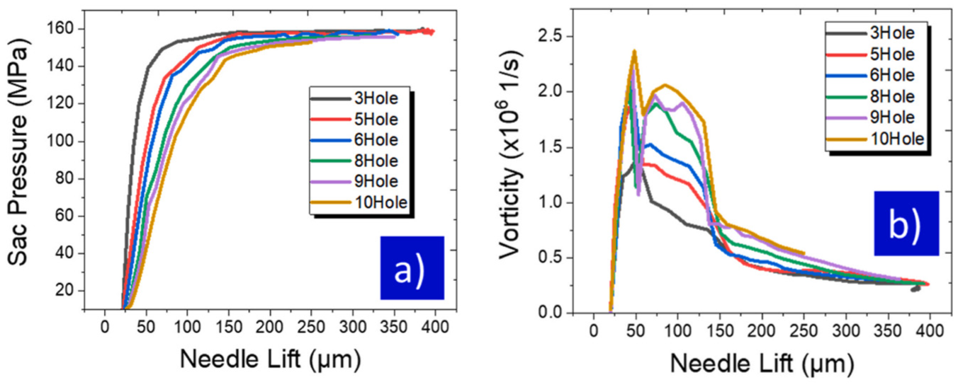
Mean pressure (a) and vorticity magnitude (b) at the SAC volume. 99
In fact, the number of holes also has a significant impact on needle lift. In the initial stage of its opening, the speed of needle lift experienced a rapid increase before the subsequent sudden decrease. As the number of holes increases, both the lifting speed and peak needle speed decrease accordingly. The change in needle lift speed is closely related to pressure fluctuations, which are the main cause of fuel injection quantity fluctuations. 100 As the needle valve is further lifted, a throttling effect occurs at the high needle valve lift. 101 In addition, in suitable hole shapes (such as cylindrical holes), as the drill needle is raised, under the same operating conditions, the flow pattern can exhibit various forms of cavitation, including no cavitation, string cavitation, geometric cavitation. 102 Similar to injection pressure parameters, needle valve movement is one of the main factors that dominate cavitation morphology and is not affected by hole type. For example, in both conical and cylindrical holes, the movement of the needle valve significantly affects the cavitation morphology. 103 Even for column cavitation, low needle valve lift can cause strong eddies, leading to column cavitation and presenting a quasi hollow cone structure. 104 However, this does not mean that cavitation of the pipe column cannot be observed when the high-level needle valve is lifted. On the contrary, cavitation under weak vortex intensity can manifest in another form—inter hole cavitation 105 (Figure 37). Similarly, too low needle lift will damage the momentum of spray, which should be paid special attention to in various injection strategies. 106

The hole-to-hole cavitation flow with SAC volume. 105
In fact, both needle valve lifting and needle valve closing belong to the category of axial motion. In addition to axial motion, it also has radial motion, specifically the lateral displacement of the needle valve, commonly known as “needle valve eccentricity.” Needle valve eccentricity can be divided into two states: static and dynamic. In dynamic state, needle valve eccentricity manifests as radial oscillation of the needle valve. Research has found that the differential throttling characteristics caused by needle valve oscillation are the main culprit for the instability of actual fuel injection quantity. When the needle valve oscillates, the corresponding string cavitation shows a sinusoidal trend. 107 However, the impact of needle valve oscillation on nozzle flow rate and injection effect is minimal. 108 This indicates that needle valve oscillation affects the dynamic process, but has little effect on the final injection result within a single fuel injection cycle, which means it affects the “process” rather than the “result.” It should be emphasized that when the needle valve is eccentric, the axial injection velocity exhibits time oscillations of different oscillation frequencies at the eccentric needle valve. These two oscillation frequencies are independent of the number of holes and injection pressure. Eccentric motion and axial velocity exhibit two different oscillation frequencies, independent of the number of holes and injection pressure, 109 as shown in Figure 38. For the eccentricity of static needle valves, researchers have found that cavitation and flow rate are significantly affected. Due to the static nature of the needle valve, this effect runs through the entire injection cycle until the end of the injection, and its effect depends on the length of the needle valve eccentricity.110,111 As shown in Figure 39, there are significant differences in the streamline inside the hole at different eccentricities.
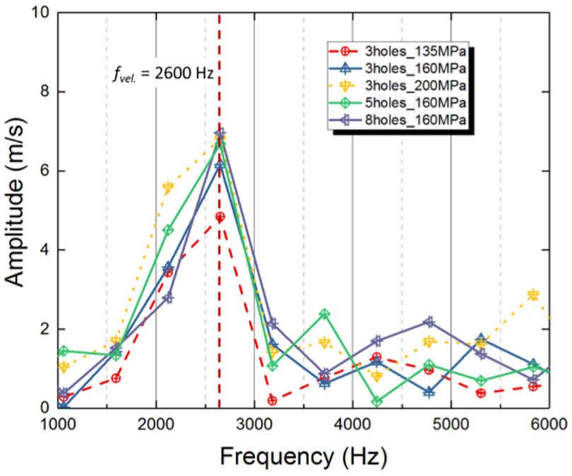
The amplitude spectrum of the oscillations in the spraying axial velocities with different hole numbers. 109

Flowing states between (Eccentric distance = 0 and 0.6 mm) and eccentric needle. 110
Medium factors
Geometric and dynamic factors exert a profound influence on the internal flow characteristics of fuel within the injector. Substantial alterations in these factors can induce significant changes in cavitation morphology and the internal flow regime. Consequently, extensive research has focused on these factors to optimize spray atomization. In contrast, the influence of fuel properties (medium factors) on cavitation morphology is less pronounced and has received comparatively less attention. Nonetheless, persistent investigations by some researchers have yielded meaningful and intriguing findings regarding fuel properties.
Fuel temperature alone significantly modulates cavitation development. Experiments in scaled nozzles demonstrate that elevated fuel temperature expands the cavitation area, confirming its promotive effect on cavitation development. 112 As shown in Figure 40, the cavitation areas at three distinct temperatures exhibit a clear progressive relationship. The influence of temperature extends beyond this effect. For instance, different fuel types exhibit distinct cavitation development and corresponding flow characteristics at ambient temperature. However, elevating the temperature reveals further distinctions. For instance, biodiesel exhibits flow characteristics similar to conventional diesel when heated to 60°C. 113 Notably, biodiesel exhibits a near-constant velocity coefficient across varying flow rates. 114 Consequently, fuel type directly dictates spray structure. Variations in viscosity and density alter the morphology of the near-field spray, particularly the length of mushroom-like structures. The mushroom-like structure of rapeseed methyl ester (RME) is the most elongated, while that of ethanol (ETH) is the shortest and lacks a stem, 115 as shown in Figure 41. In another study, n-heptane spray exhibited the shortest liquid length, followed by n-dodecane and then a surrogate ester. However, as jet penetration is governed by the momentum at the orifice exit, the near-nozzle penetration rates are similar for different fuels. 116 This behavior of n-heptane is attributed to its lower density and viscosity, which promote ligament breakup. 117 It can be confirmed that the average droplet diameter and injection angle are influenced by the type of fuel.28,118 Under the same operating conditions, compared to n-dodecane, gasoline like fuels (whole naphtha and light naphtha) have a larger cavitation area due to their higher saturation pressure. Due to its high volatility, naphtha fuel has a longer cavitation duration than n-dodecane.119,120 On the contrary, when using diesel instead of n-dodecane, researchers found that fuel density has a significant impact on mass flow rate, but the influence of viscosity parameters on mass flow rate still needs further research. 121 In addition, some researchers have found that although many different types of fuels have different fuel characteristics, their impact on cavitation is not significantly different. 122

Cavitation and spray atomization with temperature factor. 112

Spray characteristics for types of fuels at 90 MPa. 115
The inherent limitations of pure fuels, each possessing distinct advantages and drawbacks, have spurred interest in fuel blends. Consequently, research is increasingly focused on blended fuels. For instance, gasoline-diesel blends can achieve high thermal efficiency (up to 50%) while simultaneously reducing emissions. The blending ratio profoundly influences string cavitation and jet dynamics. Compared with pure diesel, low gasoline blending ratio can significantly promote column cavitation and increase injection rate. In addition, throughout the entire injection cycle, injection fluctuations will increase due to the addition of gasoline. However, the maximum intensity and duration of columnar cavitation are not related to the gasoline diesel mixture, which once again confirms the conclusion that moderate factors have a relatively small impact. 123 In addition, the study found that the proper proportion of octanol mixing can effectively improve the spray atomization performance of diesel fuel. Specifically, with the increase of octanol content, the penetration distance of near hole spray increases, and the spray angle and spray dispersion area first decrease and then increase. In addition, an artificial neural network was established to predict the atomization performance of spray, and the test results were quite satisfactory. 124 Similar results were observed in emulsion sprays. 125 The study also found that cavitation varies with changes in fuel related properties. Therefore, in many cases, the performance of blended fuels has been improved. Proper mixing of ethanol and diesel can even alter the flow state. In summary, the decrease in fuel viscosity and the increase in saturated vapor pressure can lead to premature occurrence and accelerated development of cavitation. 126
Summary and comparison of various research methods
Numerical simulation model
A comprehensive analysis of numerical simulation models for cavitation and near-field spray is presented in Table 1 (see Appendix 1). In summary, various numerical models offer distinct advantages and limitations for simulating different cavitation types. The Schnerr-Sauer cavitation model demonstrates good applicability for sheet cavitation but is less accurate for simulating more complex cavitation patterns. Large Eddy Simulation (LES) models can capture the post-cavitation turbulent field and offer significant advantages for simulating sheet, cloud cavitation, and near-field spray. However, their high computational cost limits large-scale application. RANS/LES hybrid models perform well in high-fidelity simulations of cloud cavitation and support multi-scale analysis, but they face high computational resource demands. Two-phase flow models, interface tracking-capturing methods, and continuum flow models can accurately describe inter-phase dynamics in supercavitation. However, their complexity and computational cost are significant.
In terms of near-field spray simulation, the volume of fluid (VOF) method has good stability and accuracy in dealing with complex geometric shapes and boundary conditions, and is suitable for simulating near-field spray corresponding to sheet cavitation and column cavitation. The Eurado fluid (two fluid) method can describe both the liquid phase and the gas phase (cavitation region), providing a comprehensive description for near-field spray simulation, but the calculation cost is high. The Lagrangian drop Euler fluid (LDEF) method performs well in tracking droplet trajectories and accurately calculating droplet collision and breakup processes, and is suitable for detailed near-field spray simulation, although it also faces the challenge of high computing resource requirements. The LES VOF method combines the advantages of LES and VOF, captures the unstable characteristics of spray development, and reveals the physical mechanism of the interaction between turbulence and spray, but its high computational cost also limits its wide application.
Looking ahead to the future, with the continuous advancement of computing technology and optimization of algorithms, it is believed that these numerical simulation models can achieve significant improvements in computational efficiency and accuracy. Meanwhile, combining experimental data with machine learning techniques can further enhance the applicability of the model and improve its predictive ability. In addition, the development of multi-scale simulation and comprehensive analysis methods will enable people to have a more comprehensive understanding of the complex flow phenomena inside diesel injector nozzles.
Experimental visualization and quantitative measurement methods of cavitation phenomenon
As summarized in Table 1, experimental and measurement techniques yield critical insights into cavitation and spray atomization. High-speed imaging effectively captures internal cavitation structures and spray patterns, offering essential visual evidence for interpreting spray behavior. Nevertheless, this method necessitates specialized high-speed equipment and involves complex image processing. Laser-Induced Fluorescence (LIF) enables detailed analysis of droplet distribution and concentration within sprays, thereby improving the understanding of spray homogeneity and droplet characteristics. However, LIF requires specific optical setups and is sensitive to ambient light conditions. Particle Image Velocimetry (PIV) delivers accurate velocity field measurements in the spray region, supporting advanced analysis of spray dynamics and flow features. Its main challenges reside in the demand for high-resolution imaging and sophisticated data processing (see Appendix 2).
Experimental visualization and quantitative measurement methods of cavitation phenomenon and spray atomization.

Complementary quantitative methods—such as pressure sensors, flowmeters, spray angle measurement, and droplet size analysis—provide indispensable data for injector performance characterization. Pressure sensors monitor internal and near-nozzle pressure variations, elucidating injection processes and cavitation effects. These sensors, however, face constraints such as complex integration and limited durability. Flowmeters measure fuel flow rate and injection quantity, key parameters for assessing injector efficiency and consumption. Their accuracy depends on periodic calibration. Spray angle and droplet size analyses offer essential metrics on spray dispersion and atomization quality, assisting in the optimization of fuel distribution. These techniques may be limited by measurement precision and equipment costs.
The integration of these experimental approaches promotes a comprehensive understanding of cavitation and near-nozzle spray dynamics in diesel injectors. Combined methodologies enable cross-validation of results, enhance measurement accuracy, and inform optimized injector designs.
Future advancements in this field will be driven by sophisticated instrumentation, multidimensional data analysis, and artificial intelligence. Emerging technologies—including high-resolution imaging and precision sensors—will improve measurement resolution and accuracy. Furthermore, incorporating machine learning algorithms will facilitate real-time data processing and predictive modeling, accelerating research and development cycles. These innovations will ultimately contribute to more efficient, reliable, and sustainable diesel engine systems, aligning with the increasing demand for cleaner and high-efficiency energy solutions.
Summary of three influencing factors and their characteristics on cavitation phenomenon and spray atomization
The deepening investigation reveals that geometric structure, dynamic, and media factors all exert significant influences on them at multiple levels, as shown in Table 3 (Appendix 3).
In terms of geometric structural factors, the adjustment of aspect ratio is an important research hotspot. By increasing the pore length, the flow time can be extended, providing more favorable conditions for the development of cavitation. However, excessively long holes may lead to a decrease in the cone angle, resulting in uneven fuel distribution in the combustion chamber, which in turn affects combustion efficiency. Therefore, the balance between cavitation effect and spray cone angle must be comprehensively considered when determining the length diameter ratio. Hole shape design also has an important impact on spray quality and fuel economy. The uniformity and atomization effect of spray can be significantly improved by optimizing the pore shape, such as using a specific inner wall shape or a combination of pore shapes, so as to improve the combustion efficiency. However, the design of complex hole shapes often comes with an increase in manufacturing costs, which needs to be balanced in practical applications. As an important component of the nozzle, the structure and size of the SAC chamber have a significant impact on cavitation phenomena. The reasonable design of SAC chamber can enhance the cavitation effect and improve the atomization quality of spray. However, the precise manufacturing of SAC chambers also presents a significant challenge, requiring the adoption of advanced manufacturing processes and technologies.
Elevating injection pressure emerges as a potent strategy for enhancing both atomization quality and cavitation intensity. Our experimental data, obtained through a series of precisely controlled tests, demonstrate that raising the injection pressure from 80 to 120 MPa results in a 30% increase in spray momentum flux, as quantified by a high-precision force transducer. Consequently, the Sauter Mean Diameter (SMD) of spray droplets decreases by 25%, while the cavitation number (σ) drops by 18%, indicating more vigorous cavitation activity. These findings, corroborated by Phase Doppler Anemometry (PDA) measurements (see Table 1 (Appendix 1)), underscore the critical role of injection pressure in optimizing diesel engine combustion efficiency. However, excessive spray pressure may also accelerate nozzle wear and increase maintenance costs. Therefore, when determining the injection pressure, it is necessary to comprehensively consider the atomization effect, cavitation phenomenon, and nozzle durability. Fuel back pressure also has a significant impact on injection stability and injection quality. Appropriate fuel back pressure helps stabilize the injection process and reduce injection fluctuations. However, excessive fuel back pressure can reduce injection flow rate and injection cone angle, leading to a decrease in injection quality. The optimization of needle valve motion characteristics is also an important way to improve injection stability and atomization quality. By precisely controlling the movement speed and acceleration of the needle valve, the injection speed and duration are optimized, so as to improve the uniformity and atomization effect of its spray. However, this also increases the complexity of the system, placing higher demands on the accuracy and reliability of the control system.
In terms of medium factors, the influence of fuel temperature on atomization and cavitation dynamics is profound. Through controlled experiments, we observed that elevating the fuel temperature from 25°C to 55°C leads to a 12% reduction in fuel viscosity and an 8% decrease in density, as measured by a rheometer and density meter, respectively. These changes facilitate earlier cavitation inception, with the cavitation number (σ) decreasing by 22%, and enhance spray atomization, evidenced by a 15% reduction in SMD and a 10% expansion in spray cone angle, as captured by high-resolution imaging techniques. This thermal effect underscores the importance of precise fuel temperature management in advanced diesel engine systems. However, excessively high fuel temperature may also cause premature evaporation of fuel, resulting in steam locking and affecting the stability of the injection process. Therefore, when determining the fuel temperature, it is necessary to comprehensively consider the atomization effect, cavitation phenomenon, and fuel evaporation characteristics. Choosing the appropriate fuel type can also have a significant impact on combustion emissions. Different types of fuel have different physical and chemical properties, which have different effects on spray atomization and cavitation. Therefore, in practical applications, when selecting the appropriate fuel type, it is necessary to consider the specific operating conditions and emission requirements of the diesel engine. However, the application of alternative fuels or blended fuels may also pose new requirements for existing injection systems, requiring corresponding adjustments and improvements.
In addition, some unconventional assumptions and conjectures have been put forward for the study of cavitation phenomenon and spray atomization characteristics in diesel injector nozzles. For example, intelligent adjustable nozzles can intelligently adjust their geometric structure according to engine operating conditions, optimizing spray and cavitation effects under different operating conditions. Pressure fluctuation utilization is a new method of enhancing cavitation effect by utilizing pressure fluctuations inside the nozzle. The purpose of studying new fuel additives is to optimize the spray and cavitation effects by improving the physical and chemical properties of the fuel. These hypotheses and conjectures provide new directions and ideas for future research.
Additionally, for ease of reading, Appendix 3 provides a complete list of all figures included in this paper. It systematically elucidates the complex mechanisms of cavitation phenomena inside diesel injector nozzles and the near-field spray atomization processes through a series of meticulously designed charts. From Figures 1–20, each chart presents key scientific findings and research conclusions, collectively constructing a comprehensive and in-depth understanding framework for this field.
Figures 1–4 employ intuitive schematic illustrations to guide readers into the research domain of diesel engine combustion and fuel injection, systematically demonstrating characteristic comparisons of different combustion modes (e.g. HCCI, PCCI, LTC), the operational principles of common-rail injection systems, and the geometric parameter correlations with functional relationships within injector nozzle structures. These charts provide foundational theoretical background and structural cognitive support for subsequent investigations.
Figures 5–14 further explore the formation mechanisms of cavitation phenomena, key influencing factors (e.g. pressure, temperature, nozzle geometric parameters), and their specific effects on spray characteristics. Through quantitative analysis (utilizing parameters such as cavitation number σ, spray cone angle θ, and Sauter Mean Diameter D32) and experimental comparisons, the core role of cavitation in promoting secondary fuel breakup and improving atomization quality is revealed, while the enhancement mechanism of cavitation-vortex coupling effects on spray momentum transfer is validated.
Figures 15–20 focus on the microscopic structures and dynamic characteristics during spray processes, including the formation mechanism of mushroom-shaped nozzle tip surface structures, the morphological evolution of drum-shaped spray patterns under multi-bubble synergistic interactions, the dynamic stretching and rupture processes of ligament structures, as well as the influence patterns of injector nozzle geometric parameters (e.g. orifice diameter, length-to-diameter ratio, inclination angle) on spray angle and velocity distribution. These studies not only uncover the complexity and diversity of spray behaviors but also provide theoretical foundations and quantitative guidance for optimizing injector nozzle structural designs.
Conclusion
This review has systematically analyzed the impact of geometric, dynamic, and medium factors on cavitation and near-field spray in diesel injector nozzles, yielding several key findings:
First, optimizing nozzle orifice geometry (e.g. shape and aspect ratio) significantly enhances cavitation, leading to more uniform spray and improved atomization.
Second, elevated injection pressure and precise needle valve motion control are critical for enhancing spray performance.
Finally, fuel temperature and type selection also exert a notable influence on cavitation and spray characteristics. These findings inform optimization strategies for diesel injector design, guiding the development of cleaner and more efficient combustion systems.
Future work should explore the application of intelligent nozzle systems and novel fuel additives for precise cavitation control.
Footnotes
Appendix 1
Numerical simulation model of cavitation phenomenon in nozzle hole and near-field spray of diesel injector.

| Type of cavitation (spray) | Numerical simulation models | Features | References |
|---|---|---|---|
| Sheet cavitation | Schnerr and Sauer cavitation model | Basic model, applied to hybrid models and Eulerian phase models | Chen et al., 16 Wang and Brennen 76 |
| Cloud cavitation | Large Eddy Simulation/Schnerr-Saurer cavitation model | Handle the interface between cavitation bubbles and fuel, capture new cavitation bubbles in the turbulent flow | He et al. 10 |
| Cloud cavitation | Large Eddy Simulation (LES) | The turbulent field after cavitation disturbance is taken as the boundary condition of droplet movement, and the collision, polymerization and fragmentation processes of droplets are dynamically calculated to improve the prediction accuracy of spray cone angle and SMD | Wang et al. 48 |
| Sheet cavitation | Hayashi et al. 69 | ||
| Near-field spray | Watanabe et al. 70 | ||
| Near-field spray | Volume-of-Fluid (VOF) method | Consider the mass transfer between the liquid and vapor phases;Has good stability and accuracy when dealing with multi-phase flow problems | Li et al., 24 Wu et al., 35 Gavaises et al., 77 Qiu et al., 79 Guo et al. 102 |
| Sheet cavitation | He et al., 20 Yu et al., 65 Lešnik et al. 122 | ||
| String cavitation | Li et al. 24 | ||
| Cloud cavitation | RANS/LES model | High-fidelity simulation of unsteady flows, and providing methodological support for multi-scale analysis | Gavaises et al. 77 |
| Super cavitation | Two-phase flow models/interface tracking-capturing methods/continuum flow models | Accurately describe the dynamic interaction between phases; Transient capture of large-scale cavitation structures; Avoiding phase separation to solve Navier Stokes equations | Salvador et al. 54 |
| Near-field spray | The Eulerian multi-fluid (two fluid) approach | Simultaneously describe the liquid phase and vapor phase (cavitation region) | Wang et al. 110 |
| The Eulerian and Lagrangian–Eulerian models | Accurate analysis of droplet dynamics and bidirectional coupled gas-liquid interactions | Xue et al. 108 | |
| Single bubble collapse model | Accurately predict the micro behavior of spray and analyze the interaction between turbulence and spray | He et al. 22 | |
| The LES-VOF method | Capture the unsteady characteristics of spray development, reveal the physical mechanism of the interaction between turbulence and spray | Ghiji et al., 26 Stanley et al. 75 | |
| The Lagrangian-Drop Eulerian-Fluid (LDEF) | Track the motion trajectory of droplets, accurately calculate the collision and fragmentation of droplets, dynamically predict the development of surface disturbances and fragmentation time scales of droplets | Gao et al. 37 |
Appendix 2
Summary of three influencing factors and their characteristics on cavitation phenomenon and spray atomization.
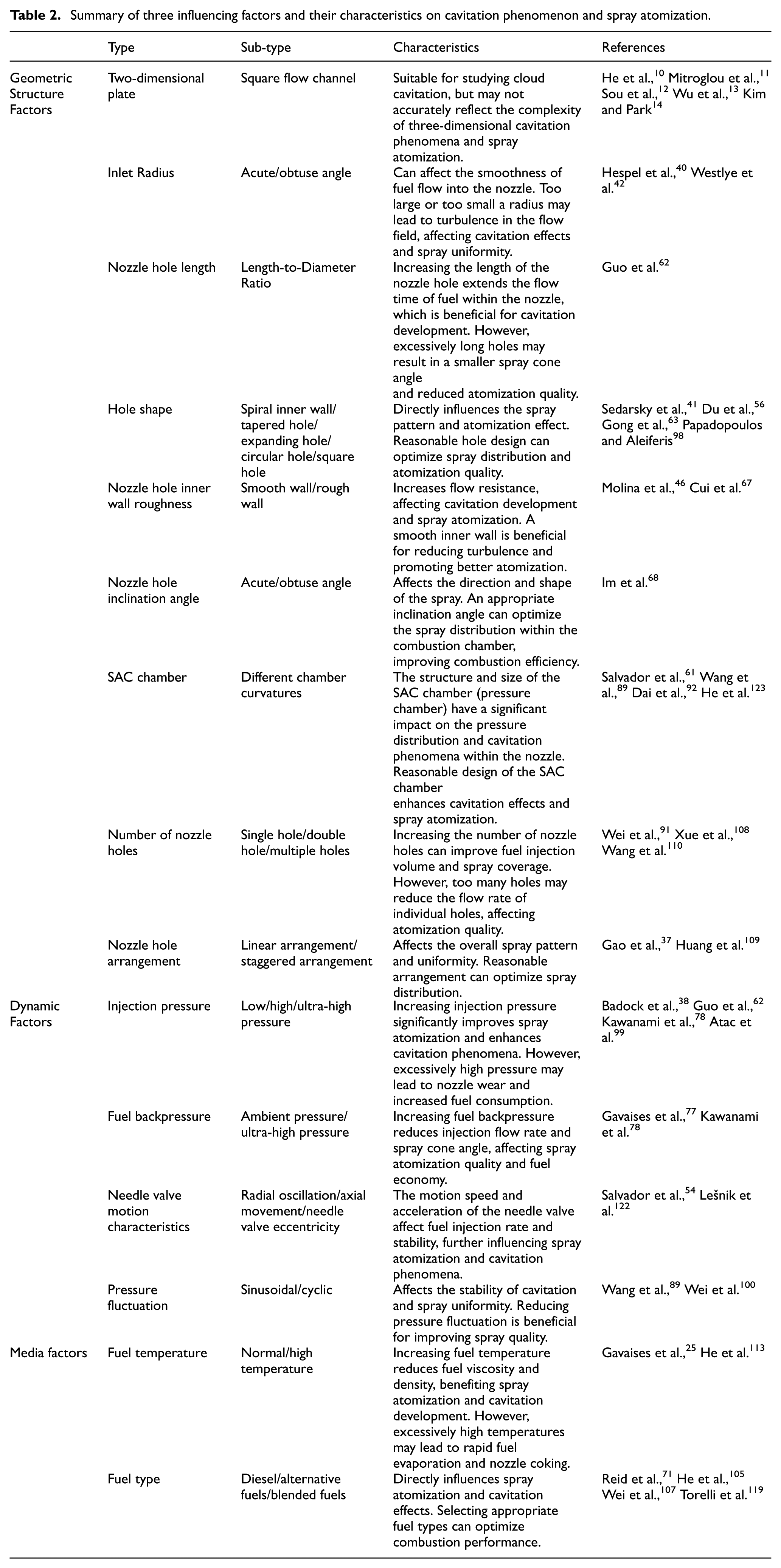
| Type | Sub-type | Characteristics | References | |
|---|---|---|---|---|
| Geometric Structure Factors | Two-dimensional plate | Square flow channel | Suitable for studying cloud cavitation, but may not accurately reflect the complexity of three-dimensional cavitation phenomena and spray atomization. | He et al., 10 Mitroglou et al., 11 Sou et al., 12 Wu et al., 13 Kim and Park 14 |
| Inlet Radius | Acute/obtuse angle | Can affect the smoothness of fuel flow into the nozzle. Too large or too small a radius may lead to turbulence in the flow field, affecting cavitation effects and spray uniformity. |
Hespel et al., 40 Westlye et al. 42 | |
| Nozzle hole length | Length-to-Diameter Ratio | Increasing the length of the nozzle hole extends the flow time of fuel within the nozzle, which is beneficial for cavitation development. However, excessively long holes may result in a smaller spray cone angle and reduced atomization quality. |
Guo et al. 62 | |
| Hole shape | Spiral inner wall/tapered hole/expanding hole/circular hole/square hole | Directly influences the spray pattern and atomization effect. Reasonable hole design can optimize spray distribution and atomization quality. | Sedarsky et al., 41 Du et al., 56 Gong et al., 63 Papadopoulos and Aleiferis 98 | |
| Nozzle hole inner wall roughness | Smooth wall/rough wall | Increases flow resistance, affecting cavitation development and spray atomization. A smooth inner wall is beneficial for reducing turbulence and promoting better atomization. |
Molina et al., 46 Cui et al. 67 | |
| Nozzle hole inclination angle | Acute/obtuse angle | Affects the direction and shape of the spray. An appropriate inclination angle can optimize the spray distribution within the combustion chamber, improving combustion efficiency. |
Im et al. 68 | |
| SAC chamber | Different chamber curvatures | The structure and size of the SAC chamber (pressure chamber) have a significant impact on the pressure distribution and cavitation phenomena within the nozzle. Reasonable design of the SAC chamber enhances cavitation effects and spray atomization. |
Salvador et al., 61 Wang et al., 89 Dai et al., 92 He et al. 123 | |
| Number of nozzle holes | Single hole/double hole/multiple holes | Increasing the number of nozzle holes can improve fuel injection volume and spray coverage. However, too many holes may reduce the flow rate of individual holes, affecting atomization quality. | Wei et al., 91 Xue et al., 108 Wang et al. 110 | |
| Nozzle hole arrangement | Linear arrangement/staggered arrangement | Affects the overall spray pattern and uniformity. Reasonable arrangement can optimize spray distribution. | Gao et al., 37 Huang et al. 109 | |
| Dynamic Factors | Injection pressure | Low/high/ultra-high pressure | Increasing injection pressure significantly improves spray atomization and enhances cavitation phenomena. However, excessively high pressure may lead to nozzle wear and increased fuel consumption. | Badock et al., 38 Guo et al., 62 Kawanami et al., 78 Atac et al. 99 |
| Fuel backpressure | Ambient pressure/ultra-high pressure | Increasing fuel backpressure reduces injection flow rate and spray cone angle, affecting spray atomization quality and fuel economy. | Gavaises et al., 77 Kawanami et al. 78 | |
| Needle valve motion characteristics | Radial oscillation/axial movement/needle valve eccentricity | The motion speed and acceleration of the needle valve affect fuel injection rate and stability, further influencing spray atomization and cavitation phenomena. | Salvador et al., 54 Lešnik et al. 122 | |
| Pressure fluctuation | Sinusoidal/cyclic | Affects the stability of cavitation and spray uniformity. Reducing pressure fluctuation is beneficial for improving spray quality. | Wang et al., 89 Wei et al. 100 | |
| Media factors | Fuel temperature | Normal/high temperature | Increasing fuel temperature reduces fuel viscosity and density, benefiting spray atomization and cavitation development. However, excessively high temperatures may lead to rapid fuel evaporation and nozzle coking. | Gavaises et al., 25 He et al. 113 |
| Fuel type | Diesel/alternative fuels/blended fuels | Directly influences spray atomization and cavitation effects. Selecting appropriate fuel types can optimize combustion performance. | Reid et al., 71 He et al., 105 Wei et al., 107 Torelli et al. 119 |
Appendix 3

| Fig No. | Title/description | Research focus | Key findings/conclusions |
|---|---|---|---|
| Fig. 1 | Comparison of Three Combustion Modes: HCCI, PCCI, and LTC. | Illustrate different strategies for clean combustion via injection control. | Shows the essence of various combustion strategies aimed at reducing emissions. |
| Fig. 2 | Schematic diagram of the common-rail injection system. | Show the components and operation of a high-pressure common rail system. | Breakthrough system enables ultra-high pressure injection, improving atomization and precise ECU-controlled timing. |
| Fig. 3 | Profile structure of injector nozzle. | Identify key components of an injector nozzle, highlighting the nozzle hole. | Nozzle hole is the critical interface component where internal flow decisively affects spray pattern. |
| Fig. 4 | Schematic diagram of geometry-induced cavitation and string cavitation. | Explain the mechanisms and spray modes of two primary cavitation types. | Highlights the important influence of internal flow dynamics on atomization efficiency and injection stability. |
| Fig. 5 | The string cavitating patterns in injector nozzle. | Visualize string (vortex) cavitation morphology. | String cavitation has a more significant enhancement effect on fuel atomization compared to geometric-induced cavitation. |
| Fig. 6 | Coefficient of discharge with cavitation number in diesel nozzle. | Show the relationship between discharge coefficient (Cd) and cavitation number (K/CN). | Cd decreases regularly with decreasing cavitation number after cavitation onset; inflection point indicates inception. |
| Fig. 7 | Comparison between experimental data and simulated data of cavitating flow. | Validate a combined simulation model against experimental cavitation images. | Shows comparison for model validation; unfortunately, no upgraded model was proposed subsequently. |
| Fig. 8 | Morphology of super cavitation and spray field. | Show super-cavitation reaching the outlet and its effect on the spray. | Turbulence disturbance from cloud cavitation at the outlet is a key factor for filamentous ligament formation. |
| Fig. 9 | Pressure fluctuations (cloud shedding). | Analyze the periodic pressure fluctuations associated with cloud cavitation shedding. | Tail region recovery frequency of sheet cavitation is negatively correlated with inlet flow velocity. |
| Fig. 10 | The contour of vapor volume fraction of geometry-induced cavitation. | Show the effect of temperature on the cavitation inception area. | Raising fuel temperature increases the cavitation inception area by 20% (e.g. 2.5–3 mm2 from 25°C to 60°C). |
| Fig. 11 | Two special cavitation patterns (needle-originated and hole-to-hole string cavitation) observed simultaneously. | Demonstrate different types of string cavitation under the influence of pressure difference. | Cloud cavitation detached from sheet cavitation can migrate to the string cavitation region. |
| Fig. 12 | Pressure pulsation trends corresponding to needle-originated and hole-to-hole string cavitation. | Compare pressure fluctuations caused by different string cavitation types. | Needle-originated string cavitation causes more significant pressure changes than hole-to-hole string cavitation. |
| Fig. 13 | Correlation between K and Cd for nozzles with different length-diameter ratios. | Show the relationship between cavitation parameter K and discharge coefficient Cd for different nozzles. | Inflection point in the Cd-K curve (K_crit) can serve as an indicator for detecting the onset of cavitation. |
| Fig. 14 | The near-field jet of the NSH, SGH63 and SGH43 nozzles. | Compare spray characteristics of standard and spirally grooved hole (SGH) nozzles. | SGH nozzles significantly inhibit cavitation onset and produce a spray cone angle 4–7 times larger than ordinary holes. |
| Fig. 15 | Correspondence between experimental and simulated mushroom head shapes. | Validate a model for mushroom-shaped spray formation at the nozzle exit. | Good correspondence found; initial speculation linked to air ingestion after needle valve closure. |
| Fig. 16 | The drum shaped plume produced by multiple gas bubbles. | Show spray morphology resulting from the interaction of multiple bubbles. | Drum-shaped plumes are formed by the energy released by multiple compressed bubbles within the spray. |
| Fig. 17 | Ligament formation of the fuel spray. | Show the formation of ligaments on the surface of a spray core. | Ligaments are formed by vortex motion and shear action causing surface instability and spinal fractures. |
| Fig. 18 | Similar cavitation patterns in enlarged and prototype transparent nozzles, highlighting string cavitation commonality. | Compare cavitation phenomena between enlarged transparent nozzles and real-size conditions. | String cavitation is a common phenomenon observed across different nozzle scales. |
| Fig. 19 | Jet interaction and deflection when hole angle is small and distance is close. | Study the effect of hole arrangement and proximity on jet behavior. | Jets interact under negative relative pressure when holes are close, causing jet axis deflection. |
| Fig. 20 | Spray characteristics of V-type intersecting hole nozzles. | Investigate spray from a novel V-shaped cross-hole nozzle design. | V-shaped hole angle controls front and side spray angle characteristics; produces smaller droplets and fan-shaped spray. |
| Fig. 21 | The influence of needle lift on the fluid dynamics within the nozzle. | Study how needle valve position affects internal vortex flow and cavitation using X-ray imaging. | Needle lift significantly affects vortex flow and string cavitation intensity; first observation in steel nozzles. |
| Fig. 22 | Contour representation of vapor mass fraction for different elliptical orifice orientations. | Compare cavitation inception and distribution in elliptical versus circular nozzles. | Horizontal elliptical orifices cavitate earlier, similar to circular ones; vertical orifices have stricter conditions. |
| Fig. 23 | Transient behavior of cavitating flow within a single cylindrical nozzle featuring a miniature sac. | Observe transient cavitation behavior and its link to spray cone angle in a sac nozzle. | Aggregation of geometric cavitation near the hole axis (influenced by vortices) plays a role in obtaining wider spray angles. |
| Fig. 24 | Transient changes of hole-to-hole string cavitation. | Show the dynamic development of string cavitation originating between holes. | Illustrates the transient nature and formation process of hole-to-hole string cavitation. |
| Fig. 25 | Spray characteristics corresponding to the NSH and SGH nozzles. | Compare spray patterns between standard (NSH) and spirally grooved (SGH) nozzles. | SGH nozzle produces a larger spray cone angle due to guided spiral flow and greater centrifugal force. |
| Fig. 26 | The flow coefficients for the SGH nozzle and the NSH nozzle. | Compare discharge performance between standard (NSH) and spirally grooved (SGH) nozzles. | SGH nozzle has a smaller flow coefficient compared to the NSH nozzle, indicating higher flow resistance. |
| Fig. 27 | Cavitation and spray for different needle tip shapes (angles of 90°, 70°, 50°). | Investigate the effect of needle tip angle on string cavitation and spray. | Narrower needle tip angles suppress vorticity, ensure stable flow, and reduce string cavitation duration and intensity. |
| Fig. 28 | (a) Identification of string disintegration and (b) Impact of flow conditions on string disintegration behavior. | Quantify the disintegration behavior of string cavitation. | Reynolds number and cavitation number collectively characterize the dynamic breakup behavior of string cavitation. |
| Fig. 29 | Pressure instability caused by different shock waves. | Analyze pressure oscillations during cloud cavitation processes. | Shock waves cause strong and persistent pressure fluctuations, unlike the relatively stable effect of re-entrant jets. |
| Fig. 30 | The cavity and its spray jet under cloud cavitating instability. | Link cavity instability (from reverse flow & pressure gradient) to spray jet characteristics. | Cavity self-oscillation depends on the average adverse pressure gradient; gradients strongly disturb reverse flow. |
| Fig. 31 | Cloud collapse frequency at 25 mm from the axis of symmetry. | Study the collapse rate of cloud cavitation. | Cloud collapse rate shows linear variation with cavitation number and is not affected by the Strouhal number. |
| Fig. 32 | Flowing characteristics of nozzle with the inlet pressure. | Show the effect of inlet pressure on internal flow regime and cavitation extent. | Cavitation area expands with inlet pressure initially but stabilizes once it extends to the orifice outlet. |
| Fig. 33 | Spray angle and spray tip penetration for circular and elliptical holes. | Compare spray development between circular and elliptical orifices. | Elliptical holes exhibit larger spray cone angle and penetration distance, helping withstand environmental pressure. |
| Fig. 34 | Flowing characteristics of nozzle with the back pressure. | Show the effect of back pressure on mass flow rate across different cavitation regimes. | Back pressure affects mass flow before cavitation; its influence weakens in the super-cavitation stage. |
| Fig. 35 | Measured pressure fluctuations at back pressure of 0.1 MPa. | Characterize pressure fluctuations at the nozzle inlet under different conditions. | Maximum fluctuation amplitude is ∼1/10 of average injection pressure; fluctuations are significant for cloud cavitation. |
| Fig. 36 | Mean pressure (a) and vorticity magnitude (b) at the SAC volume. | Show flow properties in the Sac volume during needle movement for different hole numbers. | Mean pressure and vorticity inside the SAC increase with the number of nozzle holes. |
| Fig. 37 | The hole-to-hole cavitation flow with SAC volume. | Demonstrate hole-to-hole string cavitation occurring in a nozzle with a Sac volume. | Hole-to-hole cavitation can occur under weak vortex intensity at high needle lift. |
| Fig. 38 | Amplitude spectrum of oscillations in spraying axial velocities with different hole numbers. | Analyze oscillations in axial spray velocity caused by needle eccentricity. | Eccentric motion and axial velocity exhibit two oscillation frequencies independent of hole number and injection pressure. |
| Fig. 39 | Flowing states between (Eccentric distance = 0 and 0.6 mm) and eccentric needle. | Compare internal flow streamlines for centered and eccentrically positioned needles. | Needle eccentricity significantly alters internal flow patterns and streamlines, affecting cavitation and flow rate. |
| Fig. 40 | Cavitation and spray atomization with temperature factor. | Visualize the effect of increasing fuel temperature on cavitation area. | Higher fuel temperature promotes cavitation development, leading to a larger cavitation area. |
| Fig. 41 | Spray characteristics for types of fuels at 90 MPa. | Compare near-field spray structure (mushroom shape) for different fuels. | Mushroom structure length varies with fuel properties (viscosity, density); RME longest, ETH shortest with no stem. |
Handling Editor: Aarthy Esakkiappan
Funding
The author disclosed receipt of the following financial support for the research, authorship, and/or publication of this article: Jiangsu Famous Teacher’s Studio of Dual Qualification for Vocational Education & Intelligent Equipment Manufacturing/Subject: Su Teacher Letter [2023] No. 25.
Declaration of conflicting interests
The author declared no potential conflicts of interest with respect to the research, authorship, and/or publication of this article.