
Abstract
The main influencing factors of the working clearance of the floating ring seal were analyzed in this paper, an efficient and accurate method of calculation was proposed for the radial displacement of the graphite ring, which can provide guide for structure improvement and accurately control the radial displacement of the graphite ring in the process of structure design. Improvement design was carried out on a certain floating ring seal, reducing the variation of the working clearance of the floating ring seal during changes in working conditions. After improvement, the sealing clearance of the floating ring seal decreased from 0.037–0.053 mm to 0017–0.028 mm at sealing gas temperatures of 100 °C–200 °C. With pressure differentials of 0.02–0.2 MPa, the leakage of the floating ring seal decreased by 35.4%–89.6%.
Introduction
The main function of seals in the bearing cavity of aero-engine is to effectively isolate the bearing cavity from the airflow, protect the bearings and lubricating oil from airflow with high temperature, and prevent lubricating oil leakage from the bearing cavity. Floating ring seal is a type of non-contact seal, with a smaller sealing clearance than traditional labyrinth seal and with self-centering function, it has great prospect in the sealing of bearing chamber of aero-engine.
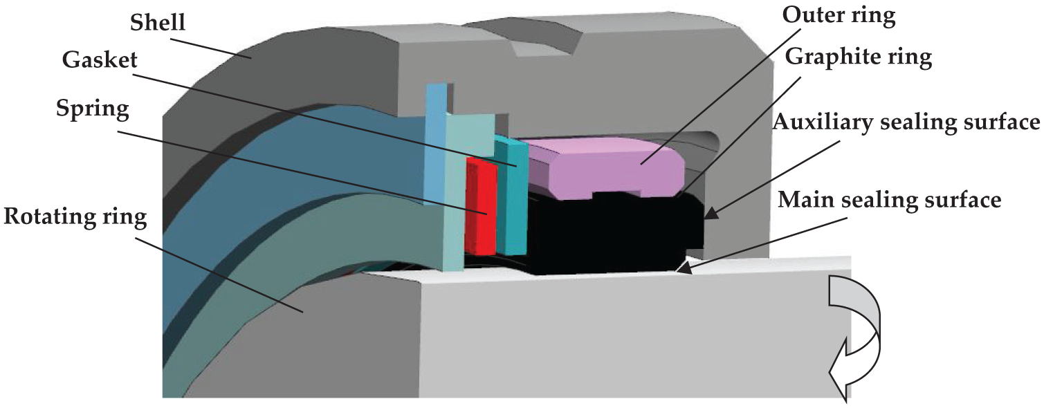
The schematic diagram of the floating ring seal is shown in Figure 1, mainly including outer ring, gasket, spring, graphite ring, shell, etc. Among them, the outer ring is embedded with the graphite ring to form a graphite ring component. Clearance fit is adopted between the rotating ring and the graphite ring, forming a main sealing surface. The graphite ring is compressed onto the surface of the shell by spring, forming an auxiliary sealing surface. During the operation of aero-engine, changes in the radial dimensions of graphite ring and rotating ring can cause variation in the working clearance of floating ring seal. If the working clearance is too large, it will lead to excessive leakage and affect the sealing performance; if the working clearance is too small, it may cause rubbing or even locking, affecting the reliability of the floating ring seal. The risks caused by unreasonable sealing clearance are shown in Figure 2. So, if the working clearance of the floating ring seal is consistent with the initial clearance, a smaller initial clearance can be designed to reduce leakage and improve reliability.
Schematic diagram of floating ring sealing.

Risks brought by changes of sealing clearance.
Scholars have conducted extensive research on the leakage characteristics of floating ring seals. Duan et al. 1 solved nonlinear control equations based on finite difference scheme and analyzed the leakage characteristics of floating ring seals. Choi et al. 2 studied the effect of floating ring seal clearance on the efficiency of turbopumps. Mariot et al. 3 studied the buoyancy characteristics of floating ring seals under certain initial clearances, rotational speeds, and pressure differentials, and compared them with experiments. Li et al. 4 compared the leakage characteristics of floating ring seals and labyrinth seals through experiments. Sun et al.5,6 investigated the influencing mechanism of fluid dynamic groove on the dynamic characteristics of integral floating ring seals. Hu et al.7,8 investigated the influence of main operating parameters (temperature, pressure difference, rotational speed) on the leakage characteristics of floating ring seals. Xia and Liu9,10 established a coupled model of fluid excitation in the sealing clearance and floating ring structure, and studied the influence of elastic deformation of the floating ring seal on the fluid excitation. Combining the characteristics of nonlinear friction, the dynamic conditions when floating ring was locking were proposed. Ha et al. 11 calculated the locking position, leakage, and dynamic coefficients of rotor based on the geometric parameters of the floating ring seal. Arghir et al. 12 analyzed the periodic, quasi-periodic, or chaotic motion of the floating ring seal under the action of unsteady hydrodynamic pressure (generated by rotor vibration), frictional force, and inertial force. Chen et al. 13 conducted numerical simulations on the clearance of floating ring seals under different shaft diameters and operating parameters. By fitting the simulation data, new empirical equations for calculating the circumferential critical Reynolds number and leakage under laminar flow conditions were obtained. Zheng et al. 14 investigated the opening characteristic of floating ring seals under multiple factors. Lee et al. 15 analyzed leakage performance, attitude angle, locking eccentricity ratio, and stiffness, damping, that determine the stability of operation. Ma et al. 16 proposed a quasi-dynamic characteristic calculation and analysis method for the floating ring seal.
Wang et al. 17 established a finite element mode of single-stage inserted floating ring structural and simulated the deformation of the floating ring seal. Wang et al.18,19 analyzed the influence of rectangular textured substrate shape on the sealing characteristics of floating ring gas film seals using finite difference method. Xu et al. 20 established a dynamic stiffness matrix and a dynamic damping matrix based on the small parameter perturbation method, and studied the variation of aerodynamic stiffness and damping coefficient with structure and working conditions. Hu et al. 21 studied the leakage of floating seals in disc cutting machines. Bae et al. 22 analyzed the relationship between the floating characteristics of floating ring seals and rotor vibration.
The floating ring seal commonly used in aero-engine, and with graphite ring components in floating ring seal, effectively alleviating the variation of working clearance under different working conditions. Working clearance analysis is an important foundation for leakage characteristics, and working clearance control is one of the main means of leakage characteristics control. Hu et al. 23 researched the mechanism of changes in the working clearance and leakage characteristics of floating ring seals. Based on the research results of this literature, this paper further studied how to control the working clearance of floating ring seals through structural design. Combined with a certain floating ring seal structure, the changes of working clearance and leakage characteristics before and after structural improvement were analyzed and compared.
Change mechanism of working clearance of floating ring seals
As shown in Figure 1, there is a certain clearance between the graphite ring and the rotating ring during aircraft engine operating, which is called the working clearance. The main influencing factors of working clearance include initial clearance, radial displacement of graphite ring, and radial displacement of rotating ring. With ttemperature changes, both the physical properties of sealing gas and the working clearance of floating ring seal have changed, which are important factors affect the leakage characteristics of floating ring seals. The changes in physical properties of sealing gas caused by temperature can be found in relevant manuals. The radial displacement of the rotating ring mainly includes radial displacement caused by thermal expansion and radial displacement caused by centrifugal expansion. After the structure of the rotating ring is determined, the radial displacement caused by thermal expansion mainly depends on the convective heat transfer between the rotating ring and the fluid. The radial displacement caused by centrifugal expansion mainly depends on the rotational speed. The linear expansion coefficient of graphite is usually between 2 ×10⁶ and 6 ×10⁶/K, and many rotating rings have linear expansion coefficients >9 ×10⁶/K. With the same temperature, the thermal expansion of rotating ring is significantly greater than that of graphite ring. If the graphite ring is directly assembled onto the rotating ring, due to the large difference in linear expansion coefficients between the materials, it is usually necessary to design a large initial clearance in order to avoid locking, which may result in a larger leakage. Therefore, the graphite ring is usually embedded with an outer ring, the outer ring and graphite ring are assembled together form a graphite ring component. When the temperature rises, the thermal expansion of the outer ring is greater than that of the graphite ring, resulting in a decrease in the assembling pressure between the outer ring and the graphite ring while the interference between the graphite ring and the outer ring decreases, and the inner diameter of the graphite ring increases, which can effectively compensate for the changes in working clearance caused by temperature (Figure 3).

Factors affecting the variation of the working clearance of the floating ring seal.
Accurately calculating the variation of the working clearance of the floating ring seal is important to analyze the leakage characteristics of the floating ring seal. In summary, the working clearance of the floating ring mainly come from four things: As the temperature changes, the inner diameter of the graphite ring changes due to thermal expansion. The linear expansion coefficients of the graphite ring and the outer ring are different, with changes in temperature, the assembling pressure changes, resulting in changes in the inner diameter of the graphite ring. With changes in temperature, the radial displacement of the rotating ring due to thermal expansion. The rotation of the rotor will cause centrifugal expansion of the rotating ring. The first two things cause changes in the inner diameter of the graphite ring, while the third and fourth things cause changes in the outer diameter of the rotating ring. The calculation equation for the working clearance is: change of working clearance = change of inner diameter of graphite ring change of outer diameter of rotating ring.
Radial displacement analysis of graphite rings
Set the assembling pressure to be uniform, denote as

The outer ring and the graphite ring are axisymmetric structures, and the equilibrium differential equation described using cylindrical coordinates is as follows:

In the equation,
The geometric equation for strain calculation is:

In the equation,
The physical equation between stress and strain is:

In the equation, E is the elastic modulus of the material (Pa);
By substituting equations (1) and (4) into the Lame equation, the following expression can be obtained:
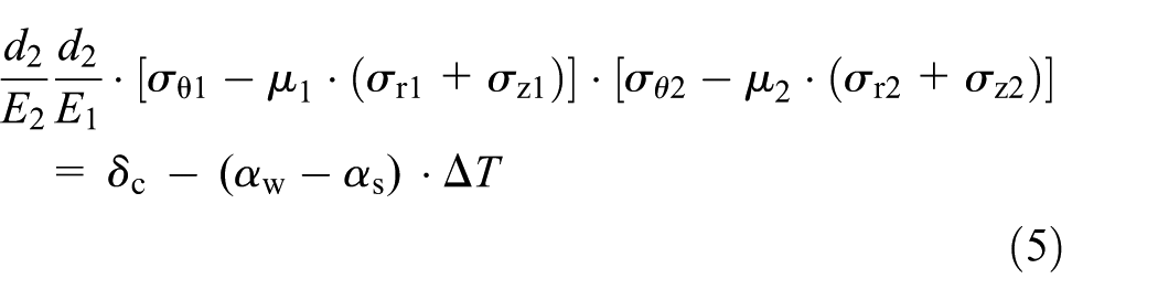
Before structural improvement, the material of the outer ring was TC4 and the material of the graphite ring was M234AO. The assembling pressure calculated by the above method at room temperature is 5.38 MPa, the assembling pressure at the sealing gas temperature of 150 °C is 4.17 MPa, and the assembling pressure at the sealing gas temperature of 250 °C is 3.24 MPa, as shown in Table 1. The radial displacement caused by the assembling pressure calculated by the finite element method are shown in Figures 4 to 6.
Assembling pressure and radial displacement at different temperatures (before improvement).


Displacement at room temperature (before improvement): (a) graphite ring and (b) outer ring.

Displacement at 150 °C (before improvement): (a) graphite ring and (b) outer ring.
Displacement at 250 °C (before improvement): (a) graphite ring and (b) outer ring.
Radial displacement of rotating ring
The radial displacement of the rotating ring can be obtained by calculating the equivalent temperature of the rotating ring based on the data obtained from the experiment. The specific process can refer to Hu et al. 8
The centrifugal expansion of the rotating ring increases with the increase of rotational speed, and the finite element method can directly analyze the centrifugal expansion of the rotating ring at different rotational speeds. The displacement cloud map of the rotating ring at a rotational speed of 26,000 r/min was calculated and shown in Figure 7. From Figure 7, it can be seen that the centrifugal expansion of the rotating ring gradually increases from the inside to the outside. On the outside of the rotating ring, the centrifugal expansion at the edge is significantly greater than that in the middle.

Displacement of rotating ring.
Analysis of leakage characteristics and experimental verification of working clearance
Taking the gas as an ideal compressible gas, the governing equation for describing the gas is:

In the equation,
Gas is a Newtonian fluid, and its constitutive equation is:

In the equation,
The equation of state for ideal gas is:

In the equation, V is the volume (m3); n is the amount of substance (mol); R is the ideal gas constant (J/(mol·K));
To verify the effectiveness of the above method, experiments were conducted on a floating ring seal. Experimental equipment mainly consists of a test bed, lubricating system, air system, testing and protection system, motor and control system, transmission system, etc. The schematic diagram of the experimental equipment is shown in Figure 8. The detailed operation process of the experiments can refer to Hu et al. 7 To verify the effectiveness of the calculation model for the leakage characteristics of the floating ring seal and determine the equivalent temperature of the rotating ring. The leakage characteristics of the floating ring seal were experimentally measured at a gas temperature of 20 °C and pressure difference is 0.02–0.2 MPa; The leakage characteristics of the floating ring seal were measured at a gas temperature of 250 °C and pressure difference is 0.02–0.2 MPa. By comparing the numerical calculation results of the leakage of the floating ring seal at a gas temperature of 20 °C with the experimental results, the effectiveness of the leakage calculation model is verified; By analyzing the experimental results of the leakage of the floating ring seal at a gas temperature of 250 °C, the working clearance of the floating ring seal is obtained, and the equivalent temperature of the rotating ring is calculated by reverse calculation. The equivalent temperature of other temperature conditions is calculated according to the method in Hu et al. 8

Schematic diagram of experimental equipment.
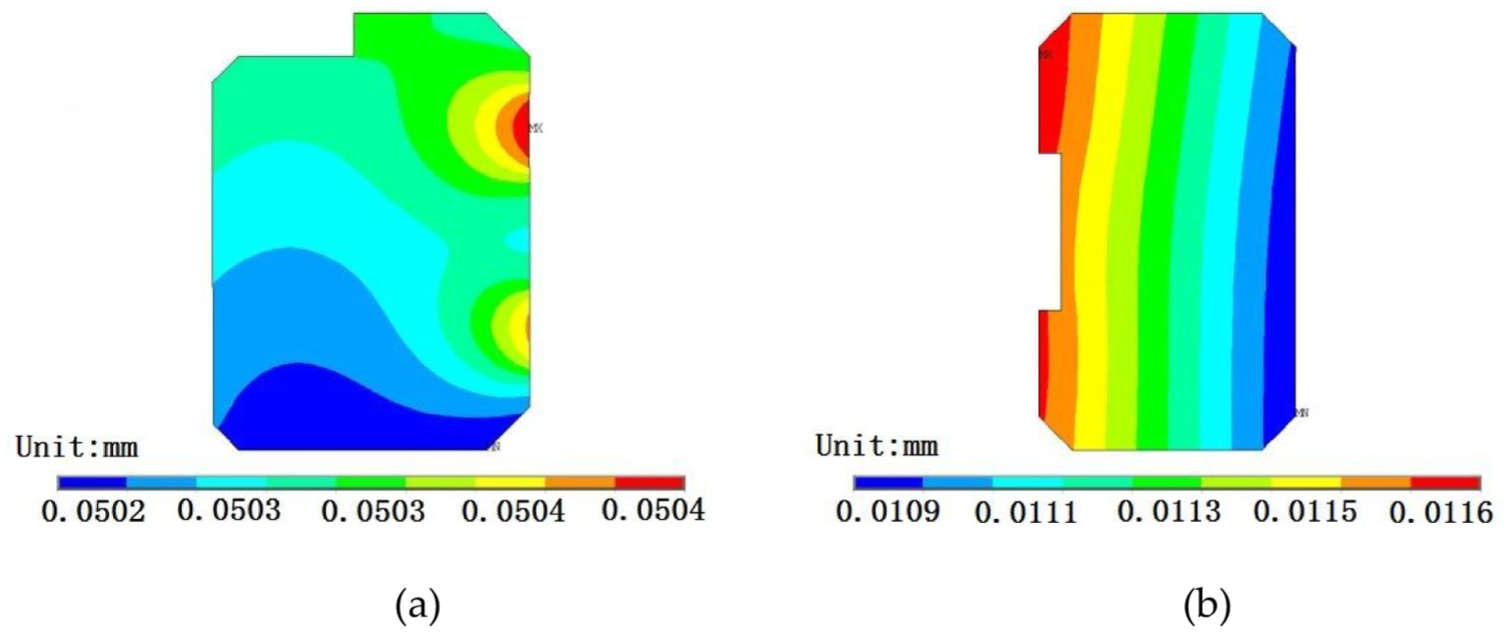
Firstly, the initial sealing clearance of the floating ring seal was measured to be 0.167 mm, and the fluid domain of the floating ring seal was extracted. A fluid calculation model was established as shown in Figure 9. The flow model is a turbulence model. The size of the elements is 0.004–0.009 mm, while it is necessary to ensure that there are four layers of elements on the main sealing surface. The model was validated for grid independence. The length of the main sealing surface is 4.5 mm and the temperature field is set to the temperature of the sealing gas. The pressure and velocity cloud maps obtained from numerical calculations at pressure differentials of 0.02, 0.1, and 0.2 MPa are shown in Figures 10 and 11. It can be seen that as the pressure differential increases, the pressure change on the main sealing surface becomes slower, and a clear vortex area is formed behind the main sealing surface. The leakage under different pressure differentials obtained from experiments and calculations are shown in Figure 12. It can be seen that the maximum error between numerical calculations and experiments is 11.2%, and the minimum error is 0.2%. The numerical calculation results are consistent with the experimental results, verifying the reliability of the numerical calculation model.

Grid mode of fluid.

Pressure distribution (20 °C): (a) 0.02 MPa; (b) 0.1 MPa; (c) 0.2 MPa.
Velocity distribution (20 °C): (a) 0.02 MPa; (b) 0.1 MPa; (c) 0.2 MPa.

Comparison of gas leakage between numerical calculation and experiment (20 °C).
By iterative solution method described in Hu et al., 8 the sealing clearance of the floating ring seal at sealing gas temperature of 250 °C was obtained to be 0.098 mm. The pressure distribution obtained from numerical calculations under pressure differentials of 0.02, 0.1, and 0.2 MPa are shown in Figure 13. It can be seen that the pressure variation is basically consistent. The velocity distribution obtained from numerical calculations at pressure differentials of 0.02, 0.1, and 0.2 MPa are shown in Figure 14. It can be seen that as the pressure difference increases, the vortex area at the rear of the main sealing surface gradually increases. The leakage under different pressure differentials obtained from experiments and numerical calculations are shown in Figure 15. It can be seen that the maximum error between numerical calculation results and experimental results is 12.8%, and the minimum error is 0.4%. The numerical calculation results are consistent with the experimental results.

Pressure distribution (250 °C): (a) 0.02 MPa; (b) 0.1 MPa; (c) 0.2 MPa.

Velocity distribution (250 °C): (a) 0.02 MPa; (b) 0.1 MPa; (c) 0.2 MPa.

Comparison of leakage between numerical calculation and experiment (250 °C).
Improvement of working clearance
The relationship between the radial displacement of the graphite ring, the diameter of the graphite ring, and the elastic modulus of the outer ring was established using equation (5). By changing the diameter of the graphite ring and the material of the outer ring, the radial displacement of the graphite ring can be adjusted to improve the working clearance. Through experiments combined with numerical calculations, it was found that the sealing clearance at room temperature and static state was 0.167 mm, and the sealing clearance at high temperature and static state became 0.098 mm. Referring to the method in Hu et al., 8 the equivalent temperature of the rotating ring at a sealing gas temperature of 250 °C is calculated to be 195 °C, and the sealing clearance at rotational speed of 26,000 r/min is reduced to 0.082 mm. The structural improvement design can be carried out by referring to the method in Hu et al. 23 to reduce the variation of sealing clearance during the operation of aero-engine (Table 2).
Assembling pressure and radial displacement at different temperatures (after improvement).
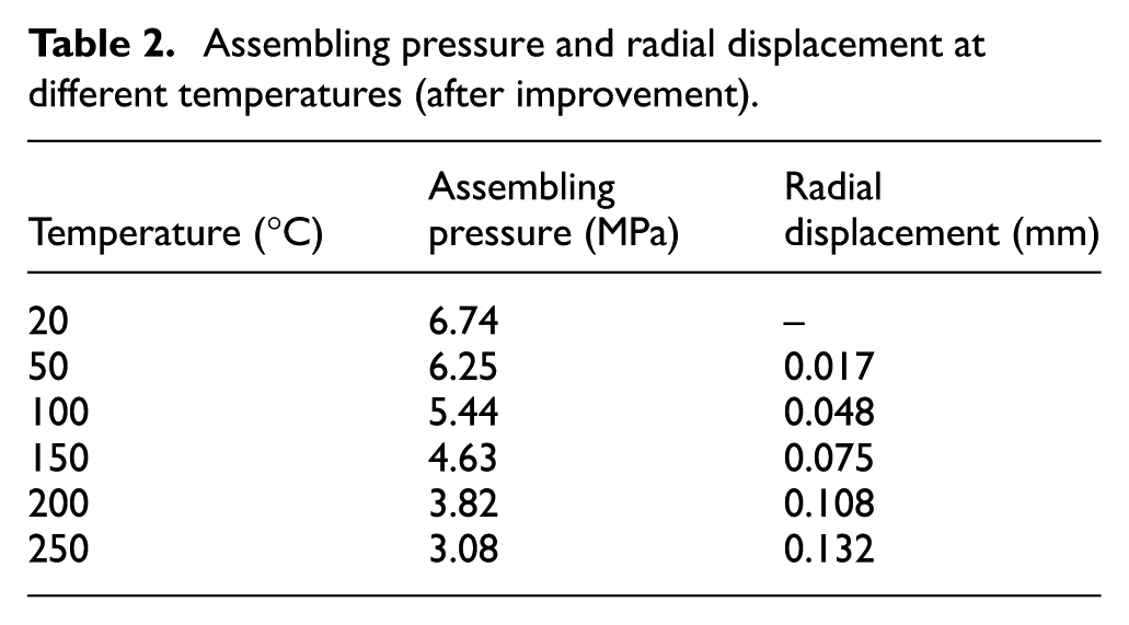
In order to keep consistency between the sealing clearance and the initial clearance, after structural improvement, the material of the outer ring is GH4220, and the material of graphite ring remains unchanged. The axial dimensions of the graphite ring and the outer ring remain unchanged, but the radial dimensions of the outer ring and the graphite ring are changed. After structural improvement, the assembling pressure at room temperature is calculated to be 6.74 MPa using the above method, and the assembling pressure at a sealing gas temperature of 250 °C is 3.08 MPa. The radial displacement cloud maps caused by the assembling pressure are shown in Figures 16 to 18.

Displacement at room temperature (after improvement): (a) graphite ring and (b) outer ring.

Displacement at 150 °C (after improvement): (a) graphite ring and (b) outer ring.

Displacement at 250 °C (after improvement): (a) graphite ring and (b) outer ring.
The comparison between the numerically calculated magnitude of interference and the actual magnitude of interference is shown in Table 3. The numerically calculated magnitude of interference is consistent with the actual magnitude of interference, indicating that the assembling pressure obtained by the above method is accurate.
Comparison between numerically calculated magnitude of interference and actual magnitude of interference.

For the structure before improvement, comparing the radial displacement of the graphite ring under the combined action of temperature and assembling pressure, it can be concluded that the sealing gas temperature increase from room temperature to 250 °C, the inner diameter of the graphite ring has increased by 0.073 mm. Through the above method, the radial displacement of the rotating ring caused by thermal expansion is to be 0.116 mm, and the centrifugal expansion of the rotating ring is 0.0132 mm. The sealing clearance is reduced by 0.058 mm at high temperature and without rotational speed. For the improved structure, comparing the radial displacement of the graphite ring under the combined action of temperature and assembling pressure, it can be concluded that the sealing gas temperature increase from room temperature to 250 °C, the inner diameter of the graphite ring has increased by 0.132 mm. Due to the unchanged thermal equilibrium conditions of the rotating ring, the radial displacement of the outer diameter of the rotating ring caused by thermal expansion is still 0.116 mm, and the sealing clearance is reduced by 0.058 mm. The centrifugal expansion of the rotating ring is 0.0132 mm. The change in the inner diameter of the graphite ring is basically consistent with the outer diameter of the rotating ring, achieving a constant sealing clearance.
Before structural improvement, the initial clearance is 0.084 mm and the working clearance is 0.026 mm when the sealing gas temperature is 250 °C. After structural improvement, the initial clearance is 0.084 mm and the working clearance is 0.085 mm when the sealing gas temperature is 250 °C. The initial clearance is basically the same as the working clearance (Figure 19).

Comparison of working clearances before and after improvement.
After structural improvement, the radial clearance variation of the graphite ring at different temperatures is basically consistent with the radial clearance variation of the rotating ring, so a smaller initial clearance can be designed. The initial clearance of the improved structure, can be reduced from 0.084 to 0.026 mm. According to the method in Hu et al., 8 the equivalent temperatures of the rotating ring at sealing gas temperatures of 100 °C, 150 °C, and 200 °C are calculated to be 84 °C, 121 °C, and 158 °C, respectively. The pre improved structure, is calculated to have sealing clearances of 0.033, 0.044, and 0.037 mm at sealing gas temperatures of 100 °C, 150 °C, and 200 °C, respectively. The improved structure, is calculated to have working clearances of 0.017, 0.019, and 0.028 mm at sealing gas temperatures of 100 °C, 150 °C, and 200 °C, respectively.
The leakage characteristics of the floating ring seal at sealing gas temperatures of 100 °C, 150 °C, and 200 °C were calculated and shown in Figures 20 to 22. It can be seen that when the sealing gas temperature is 100 °C, the gas leakage of the improved structure decreased by 77.1%–89.6%; When the sealing gas temperature is 150 °C, the gas leakage of the improved structure decreased by 63.2%–87.4%; When the sealed gas temperature is 200 °C, the gas leakage of the improved structure decreased by 35.4%–60.3%.

Comparison of leakage before and after improvement (100 °C).

Comparison of leakage before and after improvement (150 °C).
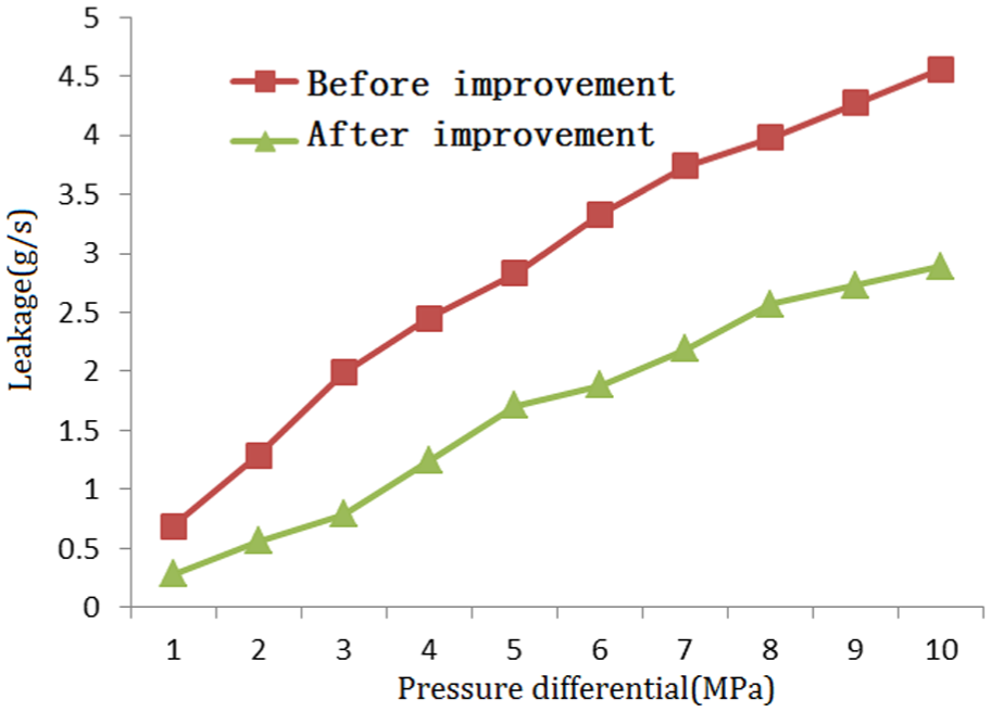
Comparison of leakage before and after improvement (200 °C).
Conclusions
This paper analyzes the changes in the sealing clearance and leakage characteristics of a certain floating ring seal, and conducts leakage characteristic experiments at room temperature and 250 °C. It proposes an improvement design for the working clearance of the floating ring seal, and the main conclusions are as follows:
1. When the temperature of the sealing gas of the floating ring seal changes, the changes in gas physical parameter and sealing clearance are the main factors causing changes in leakage characteristics. After obtaining accurate sealing clearance and simplify the stagnation zone, an effective CFD numerical calculation model can be established to obtain leakage characteristics of the floating ring seal.
2. The radial displacement of graphite ring comes from thermal expansion and changes of assembling pressure, it can be solved with finite element method. The radial displacement of graphite ring component is solved using theoretical analysis combined with finite element method. The radial displacement of the rotating ring caused by temperature is iteratively solved using experimental data and CFD numerical calculation models. The radial displacement of the rotating ring caused by rotational speed is calculated using finite element method. After obtaining the working clearance, a numerical calculation model for leakage is established, and the error between the calculated leakage and the experimental results is 0.2%–12.8%.
3. The structural size and materials of graphite ring component affect the working clearance. Based on the Lamei equation and the basic equation of elasticity mechanics, a mathematical expression has been established which can effectively control the working clearance of the floating ring seal through structural design and material selection. After improvement, the sealing clearance of the floating ring seal decreased from 0.053, 0.044, and 0.037to 0017, 0.019, and 0.028 mm at sealing gas temperatures of 100 °C, 150 °C, and 200 °C. After improvement, the variation between the working clearance and the initial clearance is significantly reduced.
4. Make the working clearance at the highest temperature consistent with the initial clearance through structural design and material selection, a smaller initial clearance can be designed to reduce leakage. The leakage decreased by 77.1%–89.6% when the sealing gas temperature was 100 °C; When the sealed gas temperature is 150 °C, the gas leakage of the improved structure decreased by 63.2%–87.4%; When the sealed gas temperature is 200 °C, the gas leakage of the improved structure decreased by 35.4%–60.3%.
Footnotes
Handling Editor: Chenhui Liang
Author contributions
Conceptualization, T.H. Validation, W.D. Formal analysis, Z.T. Investigation, J.L. Writing—original draft, W.Z. Project administration, F.L. All authors have read and agreed to the published version of the manuscript.
Funding
The authors disclosed receipt of the following financial support for the research, authorship, and/or publication of this article: This study is supported by the Technology Innovation Platform Project of AECC (No. CXPT-2023-023), and the National Natural Science Foundation of China (no. 52375077).
Declaration of conflicting interests
The authors declared no potential conflicts of interest with respect to the research, authorship, and/or publication of this article.
Data availability statement
The datasets presented in this article are not readily available due to technical limitations.