
Abstract
Topology optimization is a powerful and widely used tool in lightweight design. It can be applied to optimize the surface of an existing part by modeling a shell onto an existing finite element (FE) model and optimizing the thickness of the shell. However, if the goal is to reduce the mass, it is currently necessary to remodel the existing model with smaller dimensions before performing this type of optimization. This additional step is necessary because most available optimization tools only allow for the increase of the thickness of the shell and thus cannot be used to remove material. To address this limitation, we propose elements with negative thickness values to eliminate this time-consuming remodeling step. As a first step towards this goal, we prove that the fundamental laws of mechanics remain valid when areas are subtracted from an existing solid body and that there are no mechanical and mathematical inconsistencies. Our analysis is based on established principles of engineering mechanics. In conclusion of this paper, examples are given for the necessary next steps in preparation of the transfer of the approach to FE simulations. We also emphasize the necessity of investigating the subsequent numerical challenges resulting from our approach.
Keywords
Introduction
The discipline of lightweight design continuously gains relevance with applications in many engineering domains, especially for mobile products such as aviation, automotive, and sporting equipment. One reason is that lightweight design contributes to the sustainability of most systems or subsystems, that is, components and parts, 1 especially if no material is substituted. It does so in three ways. First, if a system is being moved or moves, lightweighting helps to save on the energy required to move it. Secondly, for lighter systems, less mass is needed to realize them, which generally saves material. Third, if less material is used, the emissions for producing the part are less, resulting in a smaller carbon footprint of any system, component, or part. Since the latter two only apply if the material used is not substituted by a material with a larger carbon footprint, the weight reduction on existing parts becomes very relevant. One way of achieving this goal is by using structural optimization on an existing part. Roughly speaking, structural optimization is based on three approaches: sizing, shape optimization, and topology optimization; see, for example, Schumacher 2 (Section 1.3) and Harzheim 3 (Sections 7.4, 8, and 9). Sizing is used to obtain the ideal thickness of parts and, therefore, their minimal weight. Shape optimization is used to alter the shape of the part, for example, to homogenize stresses on the part’s surface and reduce the part’s weight by identifying areas where material should be added or removed. This can be done by morphing the finite element (FE) mesh on the surface of the part or using parameterized computer-aided design (CAD) models (Schumacher 2 (Section 72)) and Harzheim 3 (Section 8.1)). Topology optimization is most commonly known for identifying the optimal topology of a part in a meshed design space, working with density as a design variable and a penalization factor, called the SIMP method. In addition, Osher and Sethian 4 introduced level-set methods, which optimize the boundaries of an existing shape or volume. Level-set methods became available for structural optimization at the beginning of this century (see, e.g. Wang et al. 5 ), when development in this direction began. 6 This research is ongoing, with Altair providing a beta version in 2021. 7 Current studies include parameterized level-set methods for topology optimization (e.g. Cui et al. 8 and Wang et al. 9 ). Additional approaches are being explored, such as isogeometric topology optimization for shells10,11 and the particle flow topology optimization proposed in Lin et al. 12 Both methods tend to produce truss-like structures.
Shape optimization
In shape optimization, a vector is applied to the nodes of an existing FE mesh with the direction in which the mesh will be morphed (Harzheim 3 (Section 8.2)). The advantage of the method is that material can be added and removed. Two disadvantages stand out. First, the definition of the vector can be time-consuming (Harzheim 3 (p. 187)). Consequently, this leads to the use of shape optimization for less complex parts or areas of interest in complex parts. The second disadvantage is a numerical one and contains two aspects. First, since the mesh is being morphed, there is the risk of unsteady forms if no shape function is implemented (Schumacher 2 (p. 187)) as well as the risk of an unstable process when computing, mainly if significant geometrical changes of the mesh occur (Harzheim 3 (pp. 214, 237f)). To avoid the second disadvantage, the shape can be altered using a parameterized CAD model, see Harzheim 3 (Section 8.1) and Schumacher 2 (Section 7.2), with the disadvantage of the necessity of a parameterized CAD model. A subvariant of the shape optimization via morphing is the Vertex method, where the smoothness is obtained through a filter. 13 The advantage of this method is an increase in design freedom. 14
Continuous thickness optimization of a shell
Continuous optimization, also known as variable thickness optimization, is a form of topology optimization of a shell where the design variable density is replaced by a thickness parameter.6,15 The continuity of the thickness parameter is obtained by not using a penalization factor in the optimization. 6 In the software Altair OptiStruct (https://altair.com/optistruct/), this optimization is called free-size, while Karev et al. 16 calls it topometry optimization. It can be used to obtain optimization results that can be interpreted as shear panels and not as truss structures usually obtained from topology optimization of a volume. 17 It can also be used for the dimensioning of cast parts under the premise of drawing angles. 18 In general, it can be used to optimize sheets with variable thicknesses, for example, tailored blanks. It is widely used to optimize the laminates for fiber-reinforced composites, considering fiber orientation, ply thicknesses, and laminate thickness. Since the foundation of thickness optimization is topology optimization, the advantages and disadvantages are similar. Advantages include the large variety of target functions that can be optimized, numerical robustness, and efficacy. Disadvantages include the necessity of a geometrical interpretation and numerical validation of the result. In addition, when optimizing composite laminates, the thickness parameter has to be discretized.
Application of the thickness optimization to the surface of a solid
Optimizing the surface of an existing volume model using thickness optimization and thereby applying a shell on a solid is well used in engineering. Its use is common practice in the European automotive industry but plays a minor role in the aviation industry because here, the majority of structures are shells. 19 It is very efficient, even on complex parts, because applying the shell elements onto solid elements is straightforward, and the existing FE model can be reused. The results of this optimization indicate altering the part’s surface to meet various optimization targets, for example, keeping surface stresses below a predefined limit. Experience shows it is sufficiently accurate for re-engineering purposes, especially when the suggested changes are small.
Operational advantages are numerical robustness and mostly converging optimizations. For lightweight design, an operational disadvantage of this approach is that the thickness parameter of the shell elements can only have a positive algebraic sign. Therefore, it is limited to giving indications of those elements to which material should be added. It cannot indicate areas where material should be removed. A two-step approach is commonly used to identify areas where material should be removed. First, a remodeling step is performed, where the existing part is designed to be smaller. This step often requires a new FE mesh for the smaller model. In the second step, the thickness optimization, as described above, is applied to the smaller model. An illustration is given in Figure 1, where a thickness optimization is performed on a bend cantilever beam. In the upper row of Figure 1, the thickness of the initial beam model is optimized. In the bottom row of Figure 1, the surface of the smaller, re-modeled beam is optimized. Obviously, a remodeling step is feasible for a simple structure such as the beam in Figure 1. However, for practical relevant cases, remodeling an existing structure can be quite time-consuming since it typically requires a CAD-based modification of the geometry and a subsequent meshing of the new geometry. As an example, we refer to the gearbox cover presented in Figure 2. Note that the thickness optimization does not indicate a thickness alteration for large areas of the gearbox cover. Consequently, these areas are undefined in terms of their lightweight potential.

Engineering practice for thickness optimization of surfaces shown for the example of a bend cantilever beam. (Top) Thickness optimization without remodeling; consequently, mass can only be added (green area). (Bottom) The remodeling of the initial cantilever beam gives an additional option for mass reduction (blueish area) with respect to the initial beam.
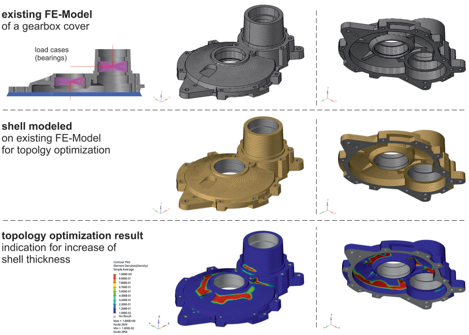
Thickness optimization of the surface on a complex part shown for the example of an existing gearbox cover.
New approach using thickness optimization of surfaces for lightweighting purposes
To remove the remodeling step described in Section 1.3 from the current method, it is necessary to identify areas where material needs to be added and where material should be removed. To do so, the optimization of the shell mesh, which is applied on top of the existing solid mesh, would need to indicate where to remove material. To obtain this indication, the parameter that represents the shell’s thickness would need to give values smaller than 0. This is not possible at the moment. These negative values for the thickness of the shell would need to be subtracted from the solid body on which the shell has been applied whilst redesigning the part. Following this methodology, the continuous thickness optimization on surfaces of a solid part can be directly used for the lightweight design of an existing part. Ideally, such an approach should be suitable for parts with complex shapes and allow for various optimization target functions such as stiffness, stress, natural frequencies, mass, etc. The working theory for this paper is that working with negative values for the thickness should be mechanically feasible as long as the basic rules of mechanics are followed. If these rules are followed, the implementation of the approach in existing optimization codes and tools should be possible. This would lead to a solution that would make the lightweight redesign of a part that has already been modeled and meshed very efficient. Although this approach is based on existing functionality within topology optimization tools, it is new because subtracting a thickness parameter from a solid FE mesh is not yet available. Two research steps are necessary before this approach can be implemented into an optimization tool. Firstly, the theory has to prove that using negative values in mechanically analyzing a structure is valid. This should be done by using existing principles of mechanics as a base. It also includes a mathematical proof of the approach, that is, that there are no undefined branch points. Secondly, it has to be determined how to implement that approach into an FE model and determine the magnitude of the deviation of the results. The deviation can be quantified by comparing the numerical result of the new approach with the analytic result. In addition, it can be compared to the result obtained by a standard method. The content of this paper is the first research step, which proves the approaches mechanical and mathematical feasibility by analyzing the basic load cases for a beam.
Motivation
In pursuing sustainability, achieving more lightweight designs without material substitution is essential. We believe that the proposed approach will enable engineers worldwide to implement lightweight design on existing parts into both new development and re-engineering efforts on a broad scale. This is particularly feasible due to the approach’s low operational threshold, especially once it is integrated into established FE tools. To enable its implementation, the following key steps must first be addressed:
Establishing the analytical feasibility of the approach.
Demonstrating its numerical feasibility while identifying and resolving potential computational challenges.
Quantifying the numerical uncertainty of the results and, ideally, defining corrective measures.
This paper focuses on laying the foundation for Step 1.
Main contributions
We lay out the analytical basis in mechanical engineering for the proposed vision of a shell topology optimization, also known as continuous thickness, free size or tompometry optimization, using negative thickness values. This vision would be an efficient tool for identifying lightweight potential in existing parts. We provide mathematical proof that the established principles of engineering mechanics apply to a cantilever beam when an area is being subtracted from its initial section (see the forthcoming Section 2). We conclude with an outlook on possible steps to further investigate the feasibility of the suggested approach in numerical modeling.
Literature review on the use and variants of thickness optimization
Optimizing the thickness of shell elements with varying thickness parameters for single elements has been part of engineering applications for about 20 years. It differs from the previously established size (or sizing) optimization of shells where all shells of a certain area, that is, a sheet, have a uniform thickness. The latter can be used to optimize the individual metal sheets of an assembled shell structure, such as a body in the white of a car, as done, for example, by Gang-Won et al. 20 with the objective of increasing the performance with a given additional weight. Continuous (or variable) optimization of the thickness parameter of a shell mesh is implemented in many commercially available optimization tools, that is, in Altair OptiStruct, Abaqus (http://www.3ds.com/products/simulia/abaqus), LS-DYNA (https://lsdyna.ansys.com), or MSC Nastran (https://hexagon.com/products/product-groups/computer-aided-engineering-software/msc-nastran). We refer to Choi et al. 21 for a performance comparison of these solvers. A comparison with a particular focus on the use of continuous thickness optimization is provided in Cervellera et al. 22 In more detail, the authors compared the performance of the truss-like result of a volume-based topology optimization and the shear plate-like result of a shell optimization implementing it on a reinforcement panel of an aircraft door. In Leiva, 23 continuous thickness optimization is applied to a shell-modeled car structure as well as to optimize its welding spots. The results show advantages regarding the optimization objectives for continuous thickness optimization over topology optimization, even more so if they are combined with additional optimization approaches, for example, shape and topography.
Continuous thickness optimization is applied in several applications. For instance, Karev et al. 16 uses it in three different models for tailoring the inner part of a vehicle hood to the dynamic load of the head impact, which is linearized by the equivalent static loads approach. 24 Volume-based topology optimization is combined in Triller et al. 25 with the thickness optimization on a mega-casting part under multiple linearized loads. This optimization is based on a split of the design space into a shell design space and a volumetric topology design space. In addition, various applications of thickness optimization can be found in student projects. We mention here the thickness optimization on the cast back structure of a car seat under multiple loads 26 and the optimization of a gearbox housing of a race car. 27 In the latter application, the shell design space for the housing is obtained by meshing the outer geometry of the CAD model, followed by a thickness optimization, which serves as the basis for the subsequent process to define the composites layup. In addition numerous publications have demonstrated the application of thickness optimization as a basis for laminate design: For instance, it has been employed in the conceptional design of an aircraft wing, 28 embedded in a multistage optimization procedure of a composite bathtub, 29 and used to compare different composite shell design methodologies, including a constant plate, a zone approach and the free-size approach. 30
The optimization-based determination of a composite layup is often based on thickness optimization 31 and is available in commercial software tools such as Altair OptiStruct. The method can be structured in three phases: In the first phase, a thickness optimization is conducted to establish an initial material orientation and placement concept. 31 The result of this first phase is a preliminary layup configuration with continuously varying thicknesses for each predefined fiber orientation. This preliminary layup is constrained by both the individual ply thickness limits and the total laminate thickness. In the second phase, a discrete interpretation of the preliminary layup is obtained. Finally, in the third phase, the stacking sequence for the final layup is optimized to satisfy manufacturing constraints. Notably, the zone-based approach commonly employed in aircraft design can be incorporated within the free-size optimization process. This three phase optimization process has been applied in various contexts, such as the design of a composite chassis cross member in a car, 32 an automotive damper dome strut bar, 33 and a sandwich structure of a composite monocoque for a quadricycle. 34 Recent applications for the use of continuous thickness optimization are, for example, the optimization of a vehicle battery box, 35 its embedding in the performance simulation for a composite chassis control arm, 36 and its use for the design of a carbon honeycomb vehicle hood. 37 Kim et al. 38 optimized a composite vehicle hood with respect to pedestrian safety by initially optimizing the fiber orientation and the stacking sequence followed by a continuous thickness optimization. A similar approach was given, for example, in Joe et al., 39 which involves firstly optimizing a set of plies arranged in the same fiber direction, secondly performing a continuous thickness optimization to trim the plies, and thirdly optimizing thickness and fiber orientation.
We conclude this literature survey by emphasizing that continuous thickness optimization is a prominent tool in lightweight design. However, its use in combination with shell elements with negative thickness, as we propose here, is neither described, nor analyzed, nor applied in the literature.
Mechanical and mathematical justification
To justify our idea mechanically and mathematically, we study the simplified setting of only two areas as depicted in Figure 3, that is, we have two areas

The general setting with two areas, where the blue area
To exemplify the resulting equation in practice, we then consider the special case of a homogeneous cantilever beam, which is depicted in Figure 4. To illustrate the result, we perform the computation in three different ways. Namely, as Scenario 1, we compute the integrals directly for a single cantilever beam. In Scenario 2, the same beam is subdivided into two smaller beams and the computations are performed for each beam individually and then combined using the parallel-axis theorem. Finally, in Scenario 3, we use our derived equation to demonstrate that the same results can also be obtained if the overall cantilever beam is given by a bigger beam from which we subtract a smaller beam.

Illustration of a cantilever beam with a subtracted smaller beam under the premise of the beams being Bernoulli beams, including the applied force
The general case
The important ingredients for the following computations are the first and second moments of area. The first moment of area, for instance, is used to compute the coordinates of the centroid of an area. They are defined as:

To obtain the coordinates of the centroid for any given area, the first moment of area must be multiplied with

as shown in Figure 5 on the left.

(Left) Basis for the computation of the coordinates of the centroid for a random area. (Right) Area consisting of three subareas, one of which is a hole.
If the area is composed of

and similarly

Let us emphasize that due to the linearity of the integral, we can also have cutout areas in the computation, in the sense that cutout areas as in Figure 5 are subtracted, that is, added with a negative algebraic sign. We thus refer to these cutout areas as negative areas or areas with a negative sign.

Similarly and according to the scheme on the left in Figure 5, the second moments are given as:
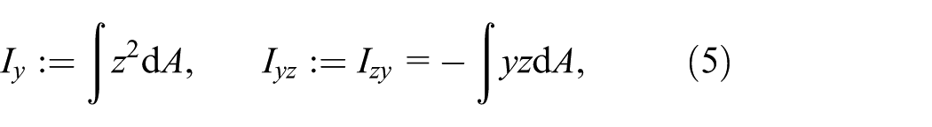

which are the rectangular moments of inertia, the product of inertia, and the polar moment of inertia (Gross et al. 40 (Section 4.2.1)).
Since the integral is additive, we can decompose an area


As common in the literature, we will use the convention


and

If centroid coordinates are used, then the equation are simplified to:

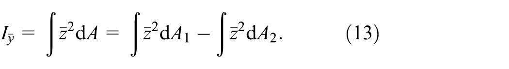
Applying the parallel-axis-theorem (cf. Gross et al. 40 (Section 4.2.2)) for each of the areas individually, we obtain:

Substituting into equation (13) yields equation (10). The results for
Theorem 1 proves that a subtracted area can be used to compute the first and second moments of a combined area. In an application, this translates into assigning a negative algebraic sign to the subtracted area and conducting the mathematical operations in mechanics accordingly. Note that from a mathematical point of view, the overall trimmed area could be negative in the sense that more area is subtracted than initially available. While the equation are still valid in this scenario, they lose their relevance in engineering applications.
Application to a Bernoulli cantilever beam
As a particular application of Theorem 1, we derive the equation for the Bernoulli cantilever beam illustrated in Figure 4. In particular, we assume that during bending, the cross-section remains perpendicular to the longitudinal axis of the beam, and the cross-section remains plain, giving a slender beam with no deflection due to shear (see, e.g. Gross et al. 40 ). To further corroborate Theorem 1, we analyze the same beam in three distinct configurations according to Figure 6.
In Scenario 1, calculations are performed for a single beam.
In Scenario 2, the beam is treated as a composite structure consisting of two smaller beams.
Finally, in Scenario 3, the beam is modeled as a larger structure with a smaller beam subtracted.

Illustration of the three scenarios that can be used to compute the second moment of inertia for the same Bernoulli cantilever.
The overall beam is the same in each scenario; hence, the moments must match. Notably, while Scenario 1 and Scenario 2 align with established results in the literature, our innovative approach in Scenario 3 directly validates Theorem 1. We emphasize that for simplicity, we perform all calculations with a negative area with constant thickness. Nevertheless, as the general theory presented in Theorem 1 details, such a restriction is not necessary for our theory to work.
For Scenario 1, we obtain:

Similarly, for Scenario 2, we compute:

Thus, the second moment of the combined cantilever beam is given as:

To compute the second moment in Scenario 3, we have:

and thus obtain:

In agreement with Theorem 1, we conclude that we can also use negative areas in the computation of the first and second moments.
Computing the deflection due to unsymmetrical bending
In the case of the unsymmetrical bending of a Bernoulli cantilever beam, the differential equations for the deflection of the beam are given as:

illustrated according to Figure 7 defining the deflection


Illustration of the unsymmetric bending of a Bernoulli cantilever beam and the definition of the deflections
Therefore, the positive algebraic sign for the second derivative of
Computing the stresses due to tension and an unsymmetrical bending
Using the principle of superpositioning, the total stresses for the cantilever beam from Figure 7 under a normal force and two load moments are given as:

where each term on the right-hand side can be solved independently. We thus argue in the following that the computation of each summand remains valid if negative areas are involved. Note that the stress due to bending has a negative algebraic sign, which results from the negative definition of
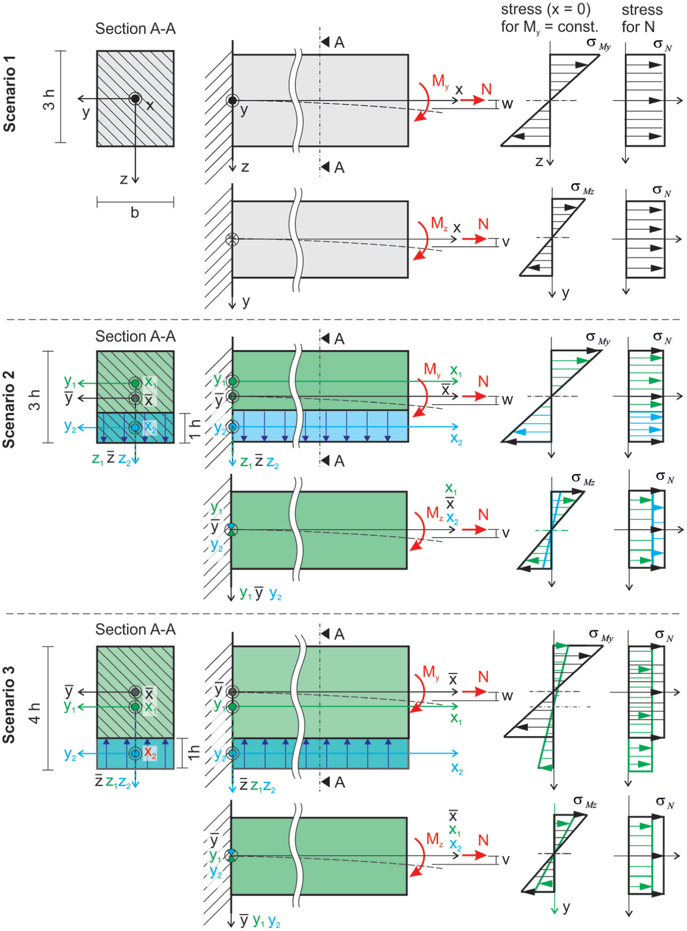
Illustration of the three scenarios to compute the bending and the stress for the same Bernoulli cantilever in three configurations to derive Theorem 1.
When including Theorem 1 into the stress equations, they can be solved; the stresses can be calculated individually and then summed. If this is done for the beam in Figure 6 in its three distinct configurations, all computations must yield the identical result. Accordingly, the suggested subtraction of a beam from a larger beam is valid for computing the correct stresses in a cantilever beam using the established principles of engineering mechanics.
Computing the deflection and stresses due to shear
In some use cases, for example, in short beams, the influence of shear may not be neglected. In such cases, the total deflection can be obtained as the sum of deflection due to bending and shear, that is,

Since the deflection due to bending has already been addressed in Section 2.3, we now focus on the deflection due to shear as given in Figure 9.

Illustration of the shear deformation in a short cantilever beam.
For the sake of simplicity, only a simple bending in

with the shear modulus

for

which yields
Application to slender beams under torsion
The premise for the following considerations is a slender beam or a shaft with a continuous section, as shown in Figure 10. Under torque, which is also known as a torsional moment

see, for example, Bender and Göhlich.
42
For both, the torsion constant section modulus

with:

We refer to see Läpple 43 (Section 11) for details. We emphasize that these equation are only valid for a rectangular sections and depend nonlinearly on the height and width of the rectangle. In particular, they cannot be applied directly to our setting with a cutout if the cutout is not designed in such a way that the resulting section is again rectangular. In such a case, as in many others, the angle of twist and the shear stress have to be approximated (Bender and Göhlich 42 (S. 398)), for example, via the FE method.
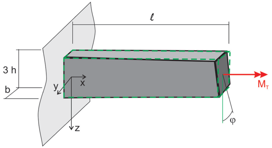
Illustration of a beam under torque also known as torsional moment.
Analogy of the approach with composite sections
In engineering mechanics, composite sections are known, see for instance (Gross et al.
44
(Kap. 8)), to model a beam consisting of any number

Illustration of a composite beam, that is, a beam consisting of combined sub-beams.
Following these two premises, the modulus of elasticity can be used as a weighing factor with one modulus of elasticity, say

This weighting factor can be used to calculate the ideal area

Using this weighting factor, the differential equation (14) for the normal bending of a combined cantilever beam according to Figure 11 is given as:

with a positive algebraic sign due to the definition of the bending moment

In light of our suggested approach of subtracting a subbeam, the combined beam with different modules of elasticity offers an additional interpretation. Instead of a negative area in equation (17), we could also assign the negative algebraic sign to the corresponding weighting factor
Summary and outlook
The use of continuous thickness optimization to identify areas on an existing body where material should be added is standard engineering practice. Our novel approach is to use thickness optimization with negative thicknesses or volumes on an existing FE model and, by this, identify areas where material should be taken off. Our research shows that the established principles of engineering mechanics are still valid for our approach. We prove mathematically that subtracting areas or volumes from an existing body is feasible for analytically computing the second moment of area. The subsequent moment of area can be applied to the mechanical principles for a cantilever beam under bending and shear. We show that there are no mathematical breakpoints for the computation of deflection, and stresses can be obtained correctly and in the established way by assigning a negative algebraic sign to the subtracted area. For this, we show that, for example, the parallel axis theorem is still valid. In the case of a torsional load, approximations are a necessity for most sections anyway, because exact solutions are only known for a limited number of sections. In case of our approach this necessity for approximations remains. By correlating our approach with the theory of beams with composite sections, we show that alternatively, the negative algebraic sign can also be assigned to the stiffness. Because the integrals used in the computational analytics of engineering mechanics are linear, we conclude that the theory underlying our approach can be generalized to established engineering mechanics. Therefore, it should be possible to implement our approach into the simulation with finite elements.
The next step is to develop FE formulations with the option of negative values for thickness, volume, or mass. Subsequently, their implementation into FE tools has to be mastered, avoiding possible singularities, for example, for the value 0. Technical issues have to be addressed, such as not allowing to reduce more thickness than the initial body supplies. After implementation into FE tools, the predictability has to be tested. For example, the prediction error between the simulation and analytic solutions has to be quantified. Once the element formulations are developed and numerical problems are identified and solved, the integration into existing commercial FE tools should be seamless without extensive modifications. The add-on approach of our idea promises widespread adoption and can trigger a paradigm shift in today’s lightweight design strategies. Moreover, we believe it bears the potential for a novel research direction, as negative volume elements are not yet considered in the numerical FE literature.
Footnotes
Acknowledgements
The authors thank Roman Reuschke for fruitful discussions and encouragement to write this paper.
Handling Editor: Chenhui Liang
Funding
The authors disclosed receipt of the following financial support for the research, authorship, and/or publication of this article: B.U. is funded by the Deutsche Forschungsgemeinschaft (DFG, German Research Foundation) – Project-ID 258734477 – SFB 1173.
Declaration of conflicting interests
The authors declared no potential conflicts of interest with respect to the research, authorship, and/or publication of this article.