
Abstract
In this study, functionally graded materials (FGMs) composed of nickel-based high temperature alloy, Inconel 625 (IN625) and austenitic stainless steel 316LSi were prepared using cold metal transfer (CMT)-based arc additive manufacturing (WAAM). The prepared 316LSi/IN625 FGMs exhibited dense structures without any signs of solidification cracking at the interface (IF). The microstructural observations showed abrupt transition across the IF, characterized by discontinuous dendritic. Elemental diffusion at the IF was confirmed by energy dispersive X-ray spectroscopy (EDS), indicating a diffusion layer of approximately 100 μm with no significant compositional changes. The 316LSi layer primarily consisted of austenitic matrix with minor δ-ferrite, whereas the IN625 layer exhibited precipitated phases on the austenitic matrix. The yield strength (YS) and ultimate tensile strength (UTS) of prepared FGMs were 514.24 and 680.32 MPa, respectively. All IF samples fractured on the 316LSi region, indicating ductile fracture due to lower UTS compared with IN625. Microhardness testing showed a gradual increase from 188.5 HV on the 316LSi side to 224.6 HV on the IN625 side along the building direction. This work demonstrates that CMT-WAAM is a promising approach for defect-free FGMs reliable interfacial bonding and desired mechanical properties.
Introduction
Functionally Graded Materials (FGMs) are advanced materials with unique property gradients, in which the composition and microstructure gradually vary to achieve different functions and properties. 1 FGMs can be tailored for specific applications, such as aerospace, automotive, defense, and biomedical engineering, enabling them to meet diverse and demanding services requirements.2,3 These materials can be produced using various techniques, including double-wire plasma welding, 4 horizontal centrifugal casting, and additive manufacturing (AM).1,5
Inconel 625 (IN625) is a nickel-based high-temperature alloy renowned for its high-temperature resistance, 6 whereas 316L is an austenitic stainless steel characterized by outstanding corrosion resistance. 7 IN625 and austenitic stainless steel are two widely used FGMs materials in aerospace, power generation, petrochemical, chemical, and marine applications. 8 The combination of these two alloys could provide an optimal balance between performance and cost 9 thereby offering significant economic advantages in industrial applications.
Laser-based AM techniques have been widely employed for the study of 316L/IN625 FGMs. For example, Tong et al. 10 utilized laser engineered net shaping (LENS) technology to fabricate gradient SS316L/IN625 joints exhibiting a tensile strength of 672 MPa and yield strength of 486 MPa. Tyagi et al. 11 investigated the stainless steel 316L-IN625 bimetallic structure based on laser wire directed energy deposition (LW-DED), and the results showed sound metallurgical bonding between SS316L and IN625, with an interfacial ultimate tensile strength of approximately 550 MPa. Martin et al. 12 monitored the phase transition behavior and thermal history evolution of 316L stainless steel and IN625 bimetallic system during laser-directed energy deposition (L-DED) using in situ synchrotron X-ray diffraction (XRD) technique. Narayan et al. 13 examined the interfacial bonding of IN625-AISI316L interface produced by autogenous laser welding and reported average tensile strength of 600 MPa at room temperature and 336 MPa at 650°C. Overall, these studies show that laser-based AM techniques have been applied for fabricating 316L-IN625 FGMs, yielding promising mechanical performance. However, the high cost of using these techniques remains a concern.
Wire arc additive manufacturing (WAAM) deposits material layer-by-layer, enabling the production of complex geometries and graded material compositions. It is a kind of directed energy deposition (DED) process that is particularly advantageous for creating components with a gradual transition in material composition. 14 As a branch of AM, WAAM has gained significant attention for its capability to fabricate FGMs with tailored properties. 15 This method offers benefits over laser-based manufacturing techniques, including reduced material waste, shorter lead times, and the ability to fabricate large components. 16 For instance, WAAM is applicable to the production or renovation of medium-to-large-scale metallic structures with intricate geometries. 17 WAAM as a means of fabricating FGMs has also been discussed in recent research. For example, Kannan et al. 18 successful manufactured SS904L/Hastelloy C-276 by using WAAM and assessed the fatigue strength and microstructural characteristics of the FGMs. Ahsan et al. 19 studied SS316L and low carbon steel FGMs and found that the interface was defect-free in the as-deposited condition, with mechanical properties enhanced through post heat-treatment. Additionally, the fabrication of SS 316L and IS 2062 E250A FGMs using tungsten inert gas welding (TIG) demonstrated superior mechanical properties, with a correlation between welding parameters and mechanical properties established through experiments and finite element analysis. 20 Pan et al. 21 produced IN625/Copper 110 FGMs and achieved a crack-free structure with minimal porosity at the interface.
WAAM has also been used in studying 316L/IN625 FGMs. For instance, Amiri and Naffakh-Moosavy22,23 found that the results obtained from JMatPro simulations were in agreement with those of WAAM experiments, indicating the feasibility of WAAM for the preparation of 316 L/IN625 structures, with average tensile strengths, yield strengths, and elongations of 487 ± 10 MPa, 300 ± 6 MPa, and 40% ± 0.15, respectively. Dokme et al. 24 compared the corrosion resistance at the IN625-AISI316L interface between continuous current gas tungsten arc welding (CCGTA) and pulsed current gas tungsten arc welding (PCGTAW), and found that the specimens produced by PCGTAW exhibited the lowest corrosion level. Harshavardhana et al. 25 employed metal inert gas (MIG) to prepare IN625-316L FGMs, however, it turned out that solidification cracks were observed at the interface between the two materials. Therefore, although WAAM has been demonstrated to be suitable for fabricating 316L-IN625 FGMs, certain limitations remain.
CMT-WAAM (cold metal transfer based on wire additive manufacturing) offers advantages, particularly in terms of lower heat input, while the temperature level influences crack formation 26 when combing materials with different properties compared with conventional WAAM. The investigations of FGMs using CMT-WAAM revealed that the microstructure and mechanical properties of the interface between SS308LSi and SS304L are influenced by the interlayer temperature control. 27 The microstructural analysis shows defect-free interfacial bonding with different grain structures under controlled and uncontrolled interlayer temperature conditions. Mechanical testing demonstrates that the interfacial strength surpasses that of the deposited walls, with ultimate tensile strengths averaging 589.1 MPa under controlled interlayer temperature and 580.9 MPa under uncontrolled interlayer temperature. Additionally, the selection of optimal parameters for CMT-deposited IN625 weld beads, such as input current, travel speed, and standoff distance, significantly affects bead geometry and mechanical properties, with optimized multi-response performance achieved at specific parameter settings. 28
However, few systematic studies on 316LSi/IN625 interfacial bonding have been conducted using the CMT-WAAM process to date. Therefore, this study aims to fill the gap in this field by investigating 316LSi/IN625 FGMs via the CMT-WAAM process. The interfacial regions are characterized by microscopically using optical microscopy (OM), scanning electron microscopy (SEM), and energy-dispersive X-ray spectroscopy (EDS) to evaluate the bonding reliability between the two materials. The mechanical properties of FGMs are examined through tensile testing, fractured morphological analysis, and microhardness measurements to assess the mechanical properties of the interface.
Experimental
A schematic illustration of the CMT-WAAM setup is shown in Figure 1. The setup comprised a 400 A TPS 4000CMT welding power supply, an inert gas welding torch, and a five-axis computer numerical control working table. A wire feeding system equipped with 316LSi or IN625 wires with a diameter of 1.2 mm, and the chemical compositions of these wires are listed in Table 1. The substrate used was a Q235 alloy plate measuring 300 mm × 150 mm × 14 mm. In this study, an alternating wire feeding deposition strategy was employed to manufacture a 316LSi/IN625 FGMs thin wall, in which 20 layers of 316LSi alloy were first deposited, followed by 20 layers of IN625 alloy. The optimized processing parameters ensuring consistent layer thickness for both materials were determined through a series of tests are summarized in Table 2.
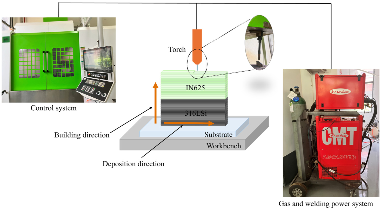
Experimental setup of CMT-WAAM system for deposition.
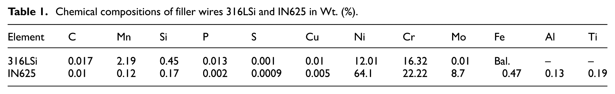
Chemical compositions of filler wires 316LSi and IN625 in Wt. (%).
Processing parameters of CMT-WAAM for manufacturing 316LSi/IN625 FGMs.

The as-deposited FGMs thin wall was machined with wire electrical discharge machine to prepare specimens for microstructural analysis and mechanical testing, as shown in Figure 2. The dimensions of the tensile specimens conform to the sub-dimensional standards specified in ASTM E8/E8M-21. 29 For microstructural characterization, specimens were sectioned at three positions along building direction of the thin wall, corresponding to the IN625 region, interface of 316LSi/IN625 (IF) and 316LSi region, respectively. The specimens for microstructural analysis were electrolytically etched with solution of phosphoric acid for 15 s following ASTM E3-11 standard. Cross-sections from IN625 region, IF, and 316LSi region were examined using OM and SEM with EDS.

Schematic illustration of thin wall and samples for test.
The tensile samples were prepared both horizontally and vertically from the thin wall, taken from the IN625, IF, and 316LSiregions respectively, with three samples of each type. The IF tensile specimen in the vertical direction consisted of both 316LSi and IN625 layers. According to the explicit position, these IF tensile samples were classified as IF-MIDDLE (located at right in the center of 316LSi and IN625), IF-HIGH (5 mm above the interface), and IF-LOW (5 mm below the interface) as shown in Figure 2. The prepared tensile samples were polished with a series of abrasive papers to a thickness of 1 mm carefully to ensure surface finish. The tensile tests were performed using a 100 kN Instron 8801 universal testing machine (UTM) at a loading rate of 1.5 mm/min. Microhardness test was conducted in accordance with ASTM E384-22. The sample for microhardness test was sectioned across IN625 to 316LSi region as shown in Figure 2. The microhardness was measured using LAILUOTE hardness tester under a load of 300 gf and with a dwell time of 30 s along the building direction at the center area of microhardness sample. Microhardness test points are arranged in a matrix pattern on sample surface. One test point was positioned at the interface, flanked by 11 test points on each side, with a spacing of 2 mm between adjacent test points resulting in a total of 23 test points in a single column. Three columns were arranged with interval of 2 mm between them. The average value of three adjacent test points along the deposition direction was taken for analysis.
Results and discussion
Microstructure evolution
The optical micrographs of the thin wall at different regions, namely IN625, IF, and 316LSi, are shown in Figure 3.

Micrographs of as-deposited FGMs: (a, b) IN625, (c, d) IF, and (e, f) 316LSi.
Figure 3(a) and (b) show the microstructure of IN625 side at different magnifications. It can be observed that the IN625 layer is mainly composed of columnar dendrites growing along the direction of heat flow, with grains arranged in a strong orientation, showing obvious columnar or plume-like structures. The columnar dendrites grow upward from the bottom of the melt pool, indicating that their growth is influenced by both the thermal gradient and the solidification rate in the melt pool. The overall microstructure is continuous and uniform, and no obvious cracks, pores, or precipitation of brittle phases are found, indicating that the IN625 side possesses good solidification characteristics and morphology under the applied process parameters.
Figure 3(c) and (d) show the microstructure of the IF region. Near the interface, the IN625 side still exhibits a columnar dendrite structure, but the grain size changes slightly, indicating the significant influence of the thermal gradient at the interface. In contrast, the 316LSi side displays typical equiaxed grains, showing obvious differences in morphology between the two sides, thus forming a clear metallurgical bonding interface. These features are similar to those observed in LENS 10 and L-DED samples. 30 No cracks, lack of fusion or intermediate brittle phases are detected at the interface, indicating a stable metallurgical bond between IN625 and 316LSi.
The microstructure of 316LSi is shown in Figure 3(e) and (f). On this side, the microstructure is mainly equiaxial grains, with clear grain boundaries and, morphology is a honeycomb structure, showing a typical austenitic stainless steel characteristics. These features indicate that the cooling rate in the center of the melt pool was relatively high, promoting the formation of equiaxial grains.
EDS analysis including EDS line scan and EDS mapping was conducted in this study. The line scan area is shown in Figure 4, covering the IF region to determine the elemental composition diffusion from IN625 to 316LSi. Figure 4 shows the typical microstructure of the macro-metallurgical bonding region between IN625 and 316LSi, consistent with the OM results shown in Figure 3(c) and (d). From top to bottom in the figure are the IN625 layer, IF region, and the 316LSi layer, respectively. Columnar dendrites growing along building direction can be observed in the IN625 side, indicating that this side experienced distinct directional solidification process. In contrast, the 316LSi side shows uniform and dense equiaxed grains, typical of the solidification of austenitic stainless steels. The interface between the two materials is relatively straight, with no obvious cracks, inclusions or unfused areas, showing that a good metallurgical combination between the two materials has been realized.

EDS mapping scan patterns around IF area.
As shown in Figure 4, the EDS line scan consists of two scan lines, namely line 1 and line 2. Line 1 starts from 316LSi side and ends at the side of IN625, while line 2 is positioned along the interface of these two materials. The results of line scan are presented in Figure 5.

EDS line scan results: (a) Line 1 and (b) Line 2.
Line 1 shows that Fe (Iron) and Ni (Nickel) are the dominant elements. Since Ni and Fe are the primary components in IN625 and 316LSi, respectively, these results confirm the expected composition of Fe and Ni. The Fe and Ni concentrations change at the IF due to the different elemental ratios of these elements in the 316LSi and IN625 regions, forming an elemental gradient ranging approximately 100 μm (from 210 to 320 µm; Figure 5(a)). A noticeable shift is also observed in the Mo fraction within the IF region as the amount of Mo differs between the two filler wires (8.7% wt.% in IN625 and 0.1 wt.% in 316LSi, as shown in Table 1). The slight variation in Cr content further supports the dilution of IN625 region into 316LSi region. When IN625 was deposited on 316LSi, the IN625 wire melted into droplets and mixed with the 316LSi molten pool, leading to the re-distribution of the elements across the IF region. Consequently, the Ni and Fe peaks gradually shift throughout the IF region. The composition of inter-dendritic precipitates mainly includes Nb and Mo, which are observed between the dendritic arms. This is particularly evident from the multiple peaks appearing in the Nb curve (Figure 5(a)). The distribution of elements along Line 2 shows fluctuation, trend for Fe and Ni, indicating mutual diffusion of elements across the 316LSi/IN625 interface, as shown in Figure 5(b).
The EDS mapping scan area covers the IN625, IF, and 316LSi region. The elemental distribution features and corresponding spectra in these three regions are shown in Figures 6 to 9.
EDS mapping result of IN625.

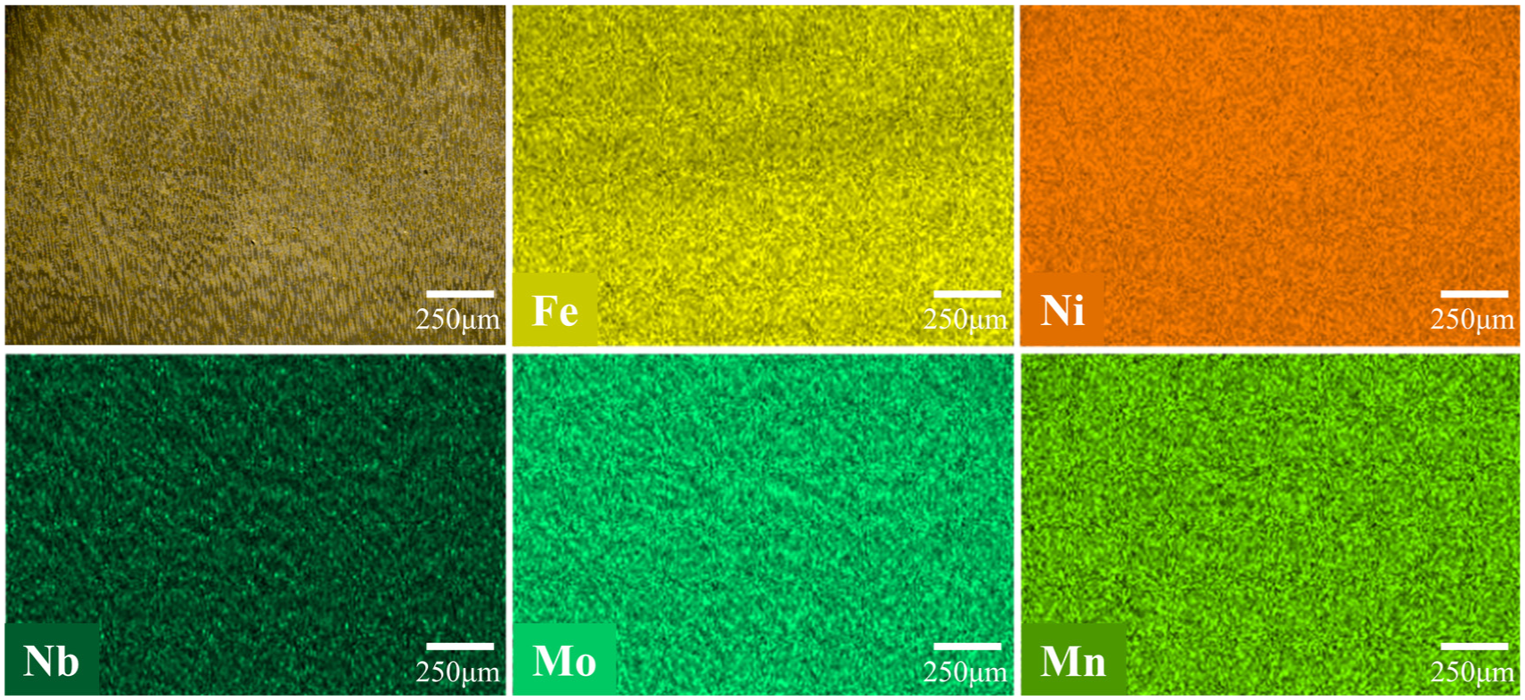
Element distribution from EDS map scan in the IF area.

EDS mapping result of 316LSi.

Elemental spectrum from EDS map scan of three regions: (a) IN625, (b) IF area, and (c) 316LSi.
Figure 7 illustrates the distribution of major elements (Fe, Ni, Mo, Mn, Nb) in IF region. The elemental distributions reveal the diffusion and mutual integration characteristics between IN625 and 316LSi.
EDS mapping result of IN625 is shown in Figure 6. From the microstructural images, columnar grains are observed, which is consistent with the OM results. In addition, the distributions of Nb and Mo also exhibit dendritic patterns, suggesting that these elements are mainly located in the interdendritic regions.
EDS mapping results show that Fe is predominant element in the 316LSi region, with its concentration gradually decreasing toward the IN625 side, suggesting a certain degree of Fe diffusion from 316LSi into IN625. In contrast, Ni exhibits an opposite distribution trend, diffusing toward the 316LSi side, particularly near the interface, where evident mutual diffusion occurs. Cr, on the other hand, displays a relatively uniform distribution across the entire region, without significant signs of enrichment or depletion, implying favorable mutual solubility and diffusion continuity between IN625 and 316LSi, as shown in Figure 9.
Mo and Nb are characteristic elements in the IN625 region, gradually decrease toward the interface, but there is a certain degree of diffusion traces near the interface. Overall, the interface region forms a clear compositional gradient band, indicating that bidirectional diffusion and mutual solvation reaction of the main elements occurred during. In particular, the cross-diffusion behavior of Ni and Fe, provides the necessary chemical basis for the metallurgical bond between the two heterogeneous materials.
Figure 8 shows the EDS mapping result of 316LSi. The main element is Fe, with Si also present. However, as indicated by the line scan results in Figure 5, the diffusion of Si is not significant, which can be attributed to its low content of only 0.45%.
Mechanical properties
Tensile properties
The engineering stress-strain curves of all the three types of samples are presented in Figure 10, with the corresponding fractured samples as inset images. The stress-strain responses are similar for all sample types, exhibiting elastic deformation before yielding, followed by a plastic formation after reaching the peak stress, and finally fracturing with reduced cross-section.

Tensile properties of CMT-WAAM thin wall: (a) IN625, (b) 316LSi, (c) 316LSi/IN625, and (d) strength and elongation of all specimens.
The average yield strength (YS) of the samples from the 316LSi, IN625, and (316LSi/IN625) IF are 420.03, 501.02, and 514.24 MPa, respectively, while the ultimate tensile strength (UTS) values are 642.14, 672.88, and 680.32 MPa. The average elongation (EL) at fracture for 316LSi, IN625, and IF samples are 34.28%, 42.86%, and 42.62%, respectively. The IF samples exhibit EL values between those of 316LSi and IN625, but YS and UTS values are considerably higher than those of 316LSi. The YS, UTS, and EL of IF samples are close to those of IN625. It should be emphasized that the YS of the IF-HIGH, IF-MIDDLE, and IF-LOW samples is nearly identical, while UTS values differ. The UTS value of IF-HIGH is the highest (707.03 MPa), followed by IF-LOW (686.15 MPa), and IF-MIDDLE shows the lowest value (647.79 MPa). In terms of EL, the value of IF-HIGH sample exhibits the largest value, whereas the EL values of IF-MIDDLE and IF-LOW are nearly the same, influenced by the content of element C. The YS and UTS values of 316LSi, IF, and IN625 obtained in this study are comparable to those reported literatures,30,31 are summarized in Table 3. The average YS and UTS of IF samples are lower than those of the samples produced via laser direct metal deposition, 32 due to coarser microstructures caused by higher heat input and larger melting pool in CMT-WAAM process, compared with the finer grains formed in laser direct metal deposition. The 316LSi and IN625 samples exhibit typical all-weld metal characteristics and demonstrate superior mechanical properties compared with wrought counterparts. 33 Also, the mechanical properties of IN625 in the current study are higher compared to previous work by Sasikumar et al., 34 attributing to differences in process parameters, heat input control, or microstructural refinement. Optimized deposition conditions in this study could have resulted in finer grains, reduced defects, or enhanced interlayer bonding, thereby improving overall mechanical performance. During the CMT-WAAM process, the formation of δ-ferrite in 316LSi layers tends to deteriorate the mechanical properties in the as-deposited condition, due to its higher brittleness compared with austenite.
Comparison of reported tensile properties of 316L/IN625 FGMs and this work.

The fractured morphologies of all tensile specimens were further examined by SEM, and the results are presented in Figures 11 to 15. All the fracture morphologies were observed at different magnifications, namely 1000×, 5000×, and 10,000×, respectively. Figure 11 presents the SEM fractography of IN625. The analysis of the fractured surface confirms the ductile fracture, corresponding to all IN625 samples that exhibited high elongation. The SEM micrographs depict the fine equiaxed dimples and randomly distributed voids without any micro-fissures. The uniform distribution of these fine dimples indicates that the fracture occurred due to the aggregation of micropores and also suggests that the samples experienced sufficient deformation during the tensile loading and possessed good plasticity. The fracture morphologies are consistent with the work reported by Gonzalez et al., 36 where IN625 was fabricated using powder-bed based AM process.
Fractography of IN625 tensile samples: (a) IN625 tensile sample, (b) 1000×, (c) 5000×, and (d)10,000×.
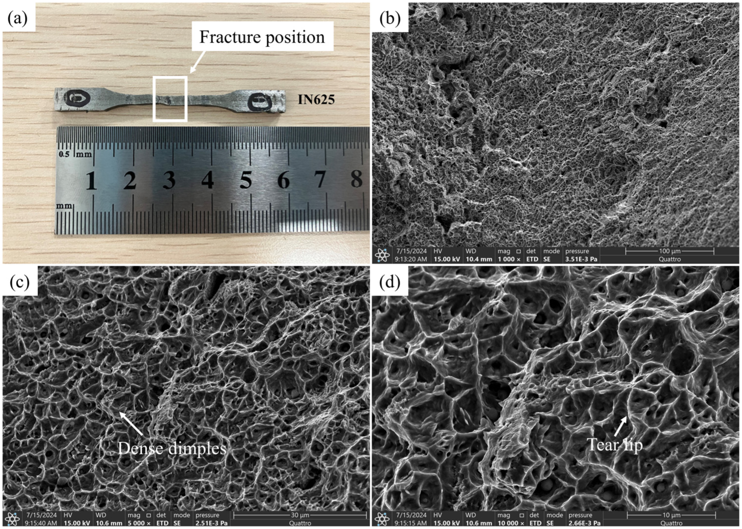
Fractography of IF-HIGH tensile samples: (a) IF-HIGH tensile sample, (b) 1000×, (c) 5000×, and (d) 10,000×.

Fractography of IF-MIDDLE tensile samples: (a) IF-MIDDLE tensile sample, (b) 1000×, (c) 5000×, and (d) 10,000×.

Fractography of IF-LOW tensile test samples: (a) IF-LOW tensile sample, (b) 1000×, (c) 5000×, and (d) 10,000×.

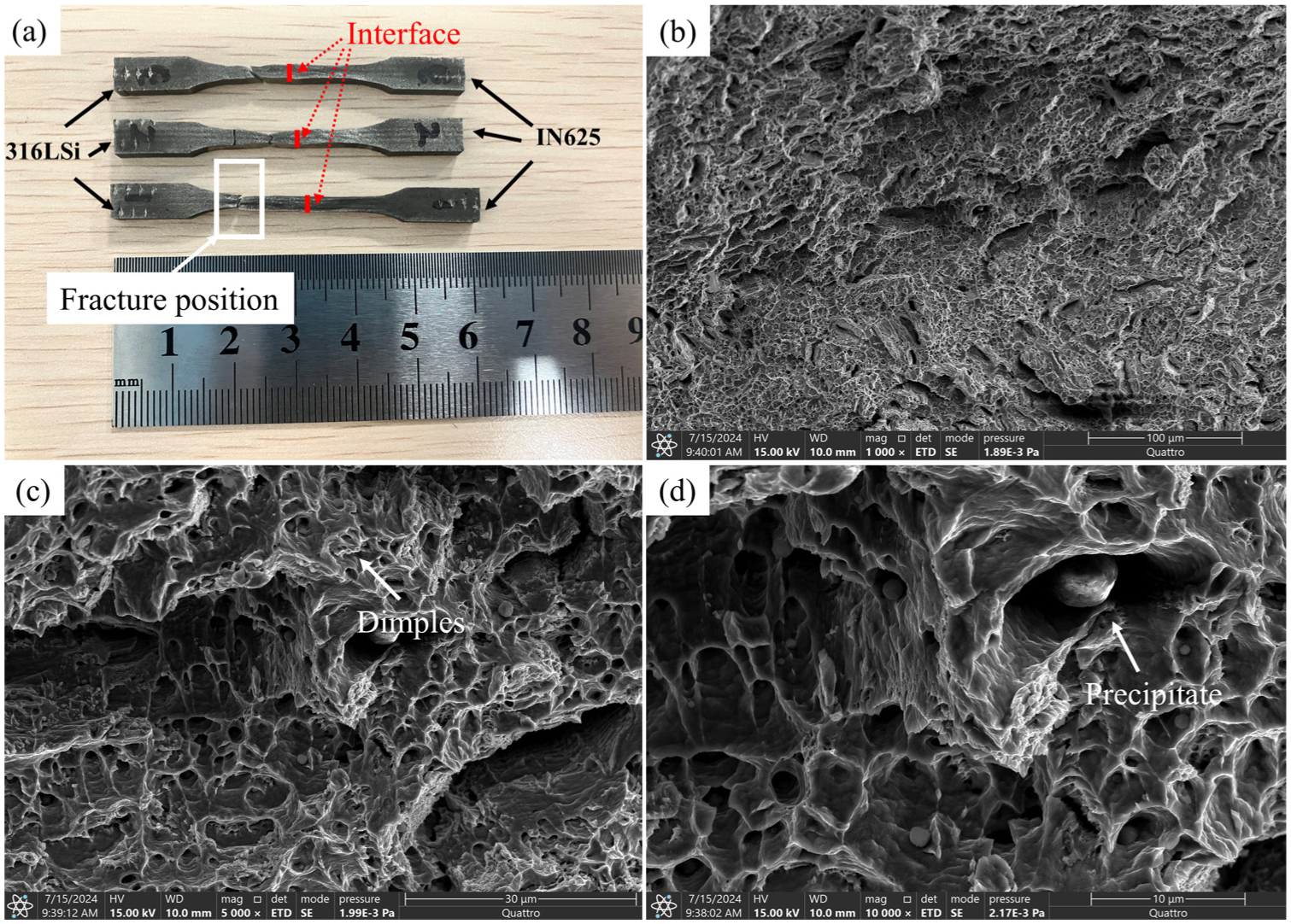
Fractography of 316LSi tensile test samples: (a) 316LSi tensile sample, (b) 1000×, (c) 5000×, and (d) 10,000×.
The SEM fractography of fractured IF tensile samples at different magnifications is shown in Figures 12 to 14, The results correspond to IF-HIGH, IF-MIDDLE, and IF-LOW samples, respectively. The 316LSi region was the site of failure for the IF tensile test samples, with fracture morphologies characterized by fine dimples, including IF-HIGH, IF-MIDDLE, and IF-LOW samples. This testifies that the tensile strength of both the IN625 side and the interface location is higher than that of the 316LSi side, as confirmed by the tensile strength of the three types of samples in Figure 10. Figure 12 shows the fracture results of the IF-HIGH samples. Dimples are the main feature, but the size of the dimples varies in size, suggesting that plastic deformation occurred during the initial stage of stretching. The sample exhibited an uneven distribution of micropores, and the response to the applied tensile force was inconsistent, leading to different growth rates of micropores. With the further increase in tensile force, the sample occurred elastic deformation and then necking, and the final fractured, resulting in dimple of different sized. The same trend was observed for IF-MIDDLE and IF-LOW samples, as shown in Figures 13 and 14. Figure 15 presents the SEM fractography of 316LSi tensile fractured sample. Figure 15(a) illustrates the reduction in cross section due to necking. Numerous equiaxed micropores with a relatively uniform distribution were observed on the tensile fractured surface, highlighting the ductile fracture mode and that the observations were in line with the previous published reports. 31 The 316LSi samples were characterized as tear lips and plastic slip traces, and the fracture surfaces are rough and without signs of brittle disintegration indicating the excellent plasticity.
Microhardness
Continuous areas from 316LSi region toward IN625 along the building direction were used to measure the hardness, as shown in Figure 14, where 0 mm represents the interface of IN625 and 316LSi. The IN625 region had an average hardness of 224.57 HV, whereas the 316LSi region had an average hardness of 188.51 HV.
The hardness trend shows that the IN625 side (−25 to −2 mm) exhibits higher hardness values, reaching up to nearly 270 HV. The hardness values lower close to the interface and become higher in the region farther from the interface, caused by the faster cooling rate of the upper layer compared with the first layer. This result is closely related to the composition of the IN625, which is enriched with elements such as Ni, Mo, and Nb, significantly increasing the hardness through solid solution strengthening and precipitation of trace elements. In addition, the microstructure in this region is dominated by columnar grains, further contributing to a higher hardness level.
For the IF region (about −2 to +2 mm), from the side of IN625 to the side of 316LSi, the hardness decreases and fluctuates to about 210 HV. Combined with microstructural observations and EDS surface scanning results, an obvious compositional transition zone exists in this region, where bi-directional diffusion of Ni and Fe occurs, and the content of Mo and Nb gradually decreases. Meanwhile the grain structure transitions from columnar crystals to equiaxial grains. This gradual change in microstructure and composition results in intermediate hardness at the interface, reflecting sound metallurgical bonding, and helps to relieve stress concentration during service. The transition in microhardness from 316LSi to IN625 results from the interpenetration of the two materials at the interface (as shown in Figures 3(d) and 5(a)). This transition can mitigate stress concentration and improve fatigue life. However, fatigue behavior requires further investigation.
On the 316LSi side (+2 to +25 mm), the hardness stabilizes and remains between 180 and 190 HV, consistent with the typical hardness level of austenitic stainless steels. The microstructure in this region is dominated by equiaxed austenitic grains, which lack significant strengthening phases and rely mainly on the Fe-Cr-Ni solid solution strengthening (Figure 16).
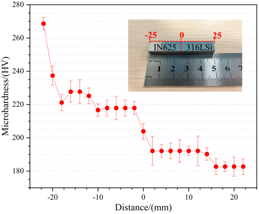
Microhardness of CMT-WAAM sample.
Conclusions
In this study, the CMT-WAAM process was employed to fabricate 316LSi/IN625 FGMs.
Based on the microstructural characterization, element analysis, tensile testing, fractography, and microhardness test performed in the as-deposited condition, the main findings can be concluded as follows.
Defect-free 316LSi/IN625 FGMs were successfully fabricated, exhibiting excellent metallurgical bonding and demonstrating the capability of CMT-WAAM process for producing high-quality 316LSi/IN625 structures.
OM observations revealed that IN625 region mainly consisted of columnar dendrites, with inter-dendritic spacing gradually decreasing toward the IF. In contrast, the 316LSi region was characterized by equiaxed grains. A distinct metallurgical interface was clearly identified between the two materials.
EDS line scan analysis revealed distinct diffusion behavior of Fe and Ni across the interface, with a diffusion distance of approximately 100 μm. EDS mapping further showed that Nb and Mo on the IN625 side were distributed in a columnar dendritic morphology, consistent with OM observations, suggesting that both two elements were distributed along the dendrite boundaries.
Tensile testing revealed that the average tensile strengths of IN625 and IF region were comparable, measured at 672.88 and 680.32 MPa respectively, both exceeding that of 316LSi region. The corresponding elongation values exhibit similar trends.
Fracture analysis results indicate that all IF specimens fractured on the 316LSi side, verifying that both the interfacial bond strength and the strength of IN625 exceeded those of 316LSi.
The overall hardness distribution exhibited higher values in the IN625 region and lower values in the 316LSi region, while the interfacial zone displayed intermediate hardness, presenting a clear transitional gradient across the IF.
Footnotes
Handling Editor: Sharmili Pandian
Funding
The authors disclosed receipt of the following financial support for the research, authorship, and/or publication of this article: The authors would like to acknowledge the Ministry of Higher Education for grant provided (FRGS/1/2022/TK10/USM/02/5) and Universiti Sains Malaysia for the support.
Declaration of conflicting interests
The authors declared no potential conflicts of interest with respect to the research, authorship, and/or publication of this article.