
Abstract
In recent years, the pressure requirements of hydraulic supports have continued to rise. However, the deficiency of initial supporting force has become a common problem in fully mechanized working faces, often leading to roof subsidence, premature separation, and a series of safety issues such as advanced break lines and coal wall spalling. To address this, a manual pressurizer was designed to achieve the required initial force through manual fluid pressurization. The device is arranged in parallel with the hydraulic control one-way valve, ensuring that it does not interfere with the normal lifting function of the hydraulic support. Based on the designed pressurization circuit, this study integrates hydraulic and mechanical technologies to design the main components, including the pressurizing cylinder, pressure control structure, one-way conduction mechanism, safety mechanism, and coordinated action system. The device is capable of achieving rapid and reliable pressurization within the emulsion system. Field tests were conducted on the ZY8500/21/45 hydraulic support bracket at the Guotun coal mine. Results show that the device significantly enhances the initial supporting force, reduces resistance build-up time, prevents roof subsidence and premature separation, and substantially improves the overall safety of the mining face. This study proposes a low-cost and high-reliability technical solution to address insufficient initial support force in deep mines, filling the application gap of mechanical booster devices in mine pressure control.
Introduction
With the increasing depth of coal mining and the advancement of fully mechanized mining technology, greater demands are being placed on the pressure capacity and supporting performance of hydraulic supports. In deep mines exceeding 1000 m, factors such as high ground pressure and complex geological structures pose severe challenges to roof control and highlight the importance of timely and effective support.
As a key parameter, the initial supporting force ensures that the support can build up resistance as designed, maintain stable working conditions, and fully utilize its supporting performance.1,2 It also suppresses premature roof subsidence, preserves roof integrity, prevents roof falls, and mitigates dynamic pressure impacts.3,4 According to design standards, the initial supporting force should exceed 80% of the rated working resistance. However, due to factors such as insufficient pump station pressure (often below rated values), system leakage, pipeline losses, limited operation time, and delayed valve response, the actual initial supporting force of many hydraulic supports is far below the required value.
This deficiency leads to a series of safety risks: Roof instability: Insufficient initial support force cannot effectively restrain roof subsidence, causing premature roof detachment, fracturing, and unstable structures that significantly increase the risk of roof collapse.
Advance of the cut line and coal wall failure: Uneven roof subsidence shifts the cut line forward and weakens coal wall stability, often resulting in large-scale rib spalling and serious safety hazards. Reduced support efficiency: Without sufficient initial contact resistance, hydraulic supports increase resistance slowly and may not reach rated values, lowering overall support efficiency. Induction of dynamic pressure: In mines prone to dynamic pressure, aggravated roof movement may act as a trigger for dynamic pressure events. 5
In recent years, research on the initial supporting force of hydraulic supports has examined its effect on support performance, studied the causes of insufficient initial force, and proposed countermeasures. These include active support systems, dual-fluid supply systems, improved liquid filling times, optimized circuit and valve designs, increased pump pressure, and reduced pipeline losses.6,7 While such measures can partially improve supporting force, most suffer from low automation, complex operation, and heavy dependence on pump station pressure. Given that many Chinese pump stations cannot meet operational requirements, achieving long-term solutions through pump upgrades requires advanced technology and extended development cycles. This makes such strategies impractical in the current downturn of the coal industry. 8
The purpose of this study is to design a mechanical-hydraulic pressurization device that enhances initial supporting force without relying on pump station upgrades. The scope of the research includes: Designing a boost control circuit in parallel with the hydraulic check valve; developing a double-acting booster cylinder based on Pascal’s principle (boost ratio >1.5); and integrating a two-position three-way manual reversing valve, safety valve, and stepped valve body.
Conducting field tests on ZY8500/21/45D supports at the 1309 working face of the Guo tun coal mine, evaluating improvements in initial supporting force, reductions in resistance build-up time, and roof stability enhancement. Ensuring that the device operates independently of the electro-hydraulic control system of the support, relying solely on mechanical-hydraulic structures without modifying pump station pressure or altering the main hydraulic support structure.
This paper therefore combines hydraulic and mechanical technologies to develop a manual pressurizer with a simple structure, convenient operation, and reliable safety. The device is arranged in parallel with the hydraulic control valve between the reversing control valve and the column inlet, ensuring that the required initial force can be achieved without altering the reversing control valve or affecting the normal lifting process.
Design and analysis of pressurizing control circuit
Design concept
The manual pressurizer is connected in parallel with the original hydraulic circuit, ensuring that the structure of the reversing valve and the normal lifting requirements of the hydraulic support remain unchanged, while enabling rapid pressurization.
The design process follows three steps: Develop a pressurization program and construct the pressure control circuit. Design the mechanical device with multifunctional structures according to the circuit. Integrate the components into a complete manual pressurizer.
Based on the relative pressure difference between the inlet and outlet, Pascal’s principle is applied. The pressurizer achieves rapid pressure boosting by utilizing the different piston areas of the cylinder cavities. 9 Since the device does not rely on electrical components, it provides higher reliability and avoids the shortcomings of traditional pressurizers. The advantages include compact size, easy installation, simple operation, rapid pressurization, and enhanced safety and stability.
Design of pressurizing control circuit
The pressurizing control circuit is the key part of the system. It is connected in parallel to the column system, adopts Pascal’s law as the operating principle, and uses a hydraulic cylinder as the pressurizing component.
During the initial lifting stage, the emulsion flows into the lower cavity through the reversing control valve, providing sufficient force for normal lifting. However, once the canopy contacts the roof, the original hydraulic circuit alone cannot generate the required pressure for the column to reach the designed initial support force. At this point, the pressurizing circuit is engaged to increase pressure.10,11
The pressurizing circuit is built around a two-position three-way manual valve, which serves as the core element for circuit control. Since the pressurizer must not interfere with the normal lifting process or the reversing valve structure, the circuit is designed to operate in parallel with the hydraulic control valve. At the preparatory stage, the piston begins its leftward movement under the influence of the control valve. Once the pressurizing control valve is actuated, emulsion from the pump station flows into the lower chamber through the pressurizing cylinder, rapidly increasing the pressure until the designed initial force is reached.
To prevent excessive pressure beyond the required initial support force, a safety valve is integrated to allow overflow from the right cavity of the pressurizing cylinder. During the lowering process, the upper cavity is filled with liquid while the lower cavity discharges. Part of the fluid enters the right cavity of the pressurizing cylinder, preparing for the next pressurization cycle, while the remaining emulsion flows out through the hydraulic control check valve.
Figure 1 illustrates the circuit, which consists of the pump station, reversing valve, check valve, hydraulic control check valve, pressurizing cylinder, column, pipelines, and other hydraulic components.

Hydraulic pressurizing control circuit.
The pump station provides supply pressure in the range of 20–31.5 MPa, consistent with both the Guo tun coal mine conditions and industry standards. The effective area of the left cavity of the booster cylinder is designed as 100 cm2, while that of the right cavity is 63 cm2. This yields a theoretical boost ratio of 1.587. With rated pump pressure, the device operates normally, but the effect may exceed target values, so the safety valve limits the working pressure within 31.7–50 MPa. The design target for the initial supporting force is set at 31.5 MPa, corresponding to the rated requirements of the ZY8500/21/45D hydraulic support.
The improved circuit connects in parallel with the hydraulic control check valve. When lifting begins, the manual reversing valve directs fluid into the lower cavity of the pressurizing cylinder. Once the canopy contacts the roof, the manual reversing valve is operated to redirect fluid into the left cavity and discharge from the right cavity, closing the check valve to prevent backflow and quickly raising the lower chamber pressure.
To avoid over-pressurization, the right chamber is connected to a safety valve that releases excess pressure. The circuit ports are configured as follows: P1/P3: Parallel connections to the left cavity of the booster cylinder. P1 serves as the inlet, P3 as the outlet during pressurization. P2/P7: Dual inlets. P2 is for the control valve, P7 is the device’s main inlet. P4/P9: Overflow outlets. P4 discharges residual fluid from the left cavity, P9 releases excess pressure through the safety valve.
P5/P6: Ports for monitoring and controlling the right cavity of the booster cylinder. P5 connects to the safety valve, while P6 is the inlet for piston actuation. P8/P10: High-pressure outlets connected to the lower cavity of the column. P8 is the device outlet, and P10 connects to the column interface.
Design of pressurizer structure
The manual pressurizer is responsible for boosting the pressure of the low-pressure emulsion. Its primary functions include oil pressurization and flow direction control. 12 The pressurization control circuit consists of a pressurizing cylinder, pressurizing control valve, check valve, safety valve, and other components. Each part must not only perform its designated function but also be integrated into a compact hydraulic valve block. This integration, referred to as the manual pressurizer for the initial supporting force of hydraulic supports, enables rational emulsion flow control and rapid pressurization.
Pressurizing cylinder
The pressurizing cylinder is the direct component for achieving pressure boosting, designed based on Pascal’s principle. Pressure enhancement is realized by utilizing the different piston areas on both sides of the cylinder. The cylinder operates in two modes: pressurization preparation and pressurization. In the preparation phase, emulsion is injected into the piston side with a smaller sectional area, while fluid from the larger side is discharged. In the pressurization phase, emulsion is injected into the piston side with the larger sectional area, driving the piston movement and achieving pressure boosting.
As shown in Figure 2, the pressurizing cylinder is composed of a base, piston, cylinder body, bent pipe, connecting steel wire, and sealing elements. The left cavity is connected to the bent pipe (port P1). The base and cylinder body are fastened by a connecting steel wire, and sealing reliability is ensured with an anti-extrusion ring and O-ring.
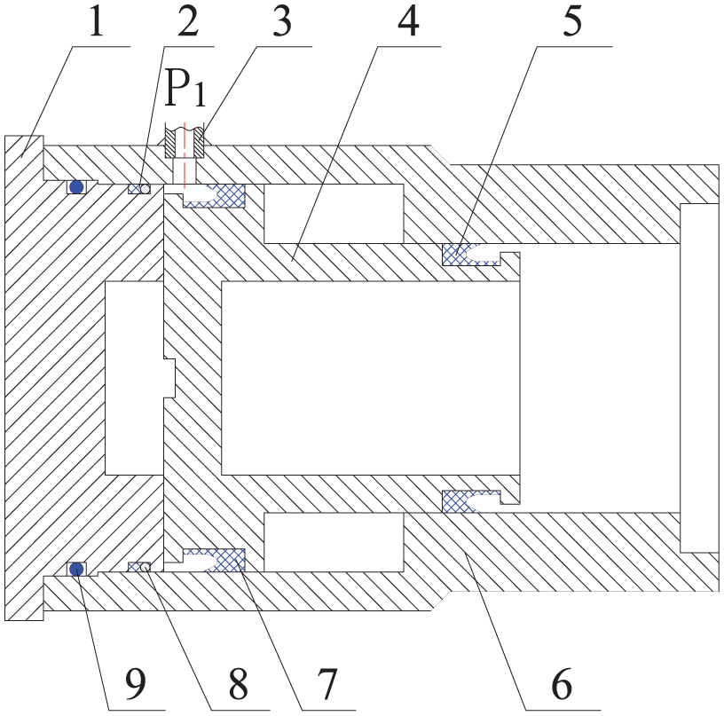
Structure of the pressurizing cylinder.
Because the piston undergoes reciprocating motion under pressure on both sides, Y-type sealing rings are installed on both ends to reduce friction and ensure reliable sealing. To minimize the overall size and weight of the device, the piston rod is designed as hollow, and the displacement is overlapped to improve compactness.
Pressurizing control mechanism
The pressurizing control mechanism is the core of the manual pressurizer, working in coordination with the pressurizing cylinder to switch the flow between the two cylinder cavities. It connects and regulates the oil circuits of the left cavity, right cavity, and the system’s supply line, thus controlling the on–off states of the oil paths.
When the supply system is connected to the rod less cavity of the pressurizing cylinder, the pressure in the right cavity exceeds that of the left cavity, closing the check valve. Therefore, the pressurizing control mechanism effectively functions as an on–off switch, directing oil flow according to pressure signals from the rod cavity.
The designed mechanism is essentially a two-position three-way manual valve. In the preparation phase, the inlet is connected to the right cavity of the pressurizing cylinder, while the outlet is connected to the left cavity. In the pressurization phase, the inlet is connected to the left cavity, and the right cavity is linked to the pipeline beneath the column.
As shown in Figure 3, during the preparation phase the emulsion flows from the pump station into port P2, pushing against the spring-loaded steel ball. Since the pressure is insufficient to open the ball, oil instead flows into the right cavity of the pressurizing cylinder via a check valve, moving the piston. The left cavity is connected to port P3, which discharges fluid through the mandrel and exits via port P4.

Pressurizing control mechanism.
When the canopy contacts the roof and pressure in the column is insufficient, the operator presses the control bar. This action moves the mandrel, opens the steel ball, and redirects fluid into the left cavity of the pressurizing cylinder, driving the piston and increasing the right cavity pressure. The column thereby rapidly achieves the required initial force.
Operators can determine the correct pressurization timing by observing the canopy–roof contact and monitoring the pressure gauge on the column. To guarantee sealing reliability, multiple seals and anti-extrusion rings are applied, ensuring smooth movement and reliable switching of the oil circuit.
Pressurizing safety mechanism
While the pressurizing control mechanism enables rapid boosting, excessive pressure may cause roof damage or other safety hazards. To prevent over-pressurization, a safety mechanism is designed, based on the structural principle of a direct-acting relief valve (DBD type) but simplified for compactness.
As shown in Figure 4, the right cavity pressure acts directly on the cone valve. The spring keeps the valve seated, and pressure adjustment is achieved with the screw. When pressure in the right cavity exceeds the preset threshold, the cone valve opens and fluid discharges through the overflow port, keeping the system pressure below the safety limit and ensuring safe operation.

Pressurizing safety mechanism.
One-way conduction mechanism
The manual pressurizer includes a one-way conduction mechanism that directs flow into the right cavity of the pressurizing cylinder. To simplify production, the design uses a steel ball and spring structure rather than a complex hydraulic control valve (Figure 5).

One-way conduction mechanism.
When emulsion enters port P7, the oil pressure lifts the steel ball, opening the inlet to the right cavity (P6). When the pressurizing control mechanism is activated and pressure builds in the right cavity, the steel ball is forced back onto the seat, preventing reverse flow and ensuring reliability.
Main valve body
The main valve body integrates all pipelines and functional valves into a compact structure, coordinating their logical actions. It strictly regulates emulsion flow in accordance with the pressurizing circuit. The design adopts a stepped configuration, ensuring compatibility with the pressurizing cylinder and enhancing sealing performance. 13 After analyzing, the design of main valve body mechanism is as shown in Figure 6.

Main valve body.
The main valve body houses installation ports for all functional valves and pipe connections. For example, port P3 connects the left cavity to the control valve, while port P4 discharges excess fluid. Port P7 serves as the main inlet, distributing fluid to the control valve and one-way valve before entering the right cavity (P6). Port P8 is the outlet, and port P9 is the overflow outlet for the safety valve.
Overall structure of pressurizer
Based on the design of each individual component, the overall installation of the manual pressurizer can be assembled. The main valve body serves as the central support, integrating all functional mechanisms through a rational layout. The structure adopts a stepped configuration between the valve body and the pressurizing cylinder to ensure proper sealing and structural compatibility.
The alignment of liquid ports is carefully designed: port P3 must remain parallel to port P1 with the same opening direction. The bent pipe is welded between the valve body and the cylinder block, enhancing structural stability and simplifying installation. For external connections, pipe joints are welded at ports P7 and P8, facilitating integration with the pipeline system. In addition, a mounting base plate is welded to the bottom of the pressurizing cylinder to improve overall stability.
Figure 7 shows the complete assembly of the manual pressurizer. The device is installed in parallel between the hydraulic reversing control valve and the column inlet. The working process proceeds as follows: Pressurization preparation: When the pump station starts, the reversing control valve directs emulsion into the bottom cavity of the column through the main valve body and the hydraulic control one-way valve. Simultaneously, another flow path passes through port P7 into the device. The emulsion flows via the one-way conduction mechanism into the right cavity of the pressurizing cylinder, pushing the piston leftward. Fluid from the left cavity exits sequentially through port P1, the bent pipe, port P3, the mandrel channel, valve seat, and finally port P4. This completes the preparation stage. Pressurization: Once the canopy contacts the roof, the operator actuates the pressurizing control mechanism. Emulsion from port P1 flows into the lower chamber of the pressurizing cylinder, driving the piston upward. Pressure in the upper chamber rises rapidly, and the emulsion exits through ports P8 and P10 into the column cavity. The column thus reaches the required initial supporting force quickly. Overpressure protection: If pressure in the upper chamber exceeds the safety threshold, the steel ball in the safety mechanism opens, and excess fluid discharges through port P9, preventing over-pressurization. Unloading and reset: After liquid supply is complete, the reversing control valve closes the column’s bottom cavity. When unloading, the spring in the pressurizing control mechanism automatically resets the steel ball, mandrel, and bar to their initial positions, preparing the device for the next cycle. Because hydraulic supports in different mines require varying levels of initial pressure, there is no fixed standard for the boost ratio or valve body response of the pressurizer. The design can be adjusted to suit specific conditions and specifications.14,15
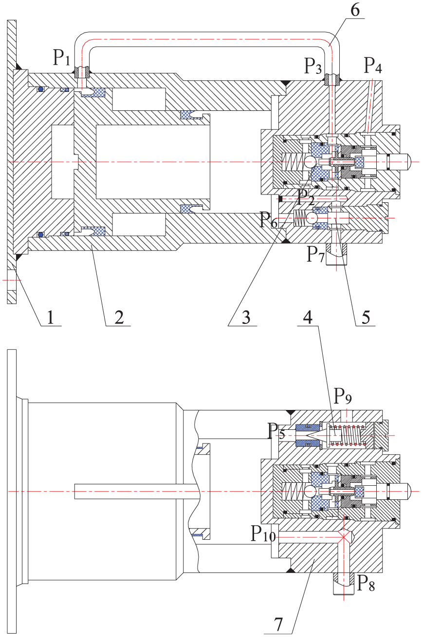
Manual pressurizer assembly.
Overall, the device features a compact structure, convenient installation, reliable safety, and effective pressurization performance, making it well-suited for field application.
Application and field test
The manual pressurizer was field-tested on the 1309 fully mechanized coal mining face at Guo tun Coal Mine, using ZY8500/21/45 hydraulic supports. The site installation is shown in Figure 8.

Site installation: (a) ground installation view and (b) underground installation view.
Test arrangement
We collected paired measurements from 30 hydraulic supports (0#, and ±2 to ±30) on the same working face, before and after installing the manual pressurizer. For each support, we recorded initial supporting force (MPa), initial support time (s), and resistance build-up time (s). Differences (after−before) were tested for normality using the Shapiro–Wilk test. If normally distributed, paired t-tests were applied; otherwise, Wilcoxon signed-rank tests were used. We report mean ± standard deviation (SD), mean differences with 95% confidence intervals (CI), p-values, and effect sizes (Cohen’s dz for t-tests; r = Z/√N for Wilcoxon tests). Plots include paired dot plots with connecting lines and group mean with 95% CI. Sensitivity analyses (outlier removal using the IQR rule; covariate “distance to 0#”) were conducted to confirm robustness. All analyses were performed in [software, e.g. SPSS 28.0 / R 4.3.1].
In Figure 9, the x-axis of all subfigures represents the hydraulic support number, where 0# denotes the central support and ±2 to ±30 correspond to the supports selected at equal intervals on both sides. The y-axis varies according to each subfigure: In Figure 9(a), the y-axis indicates the initial supporting force (MPa); In Figure 9(b), the y-axis indicates the initial support time (s); In Figure 9(c), the y-axis indicates the resistance build-up time (s).
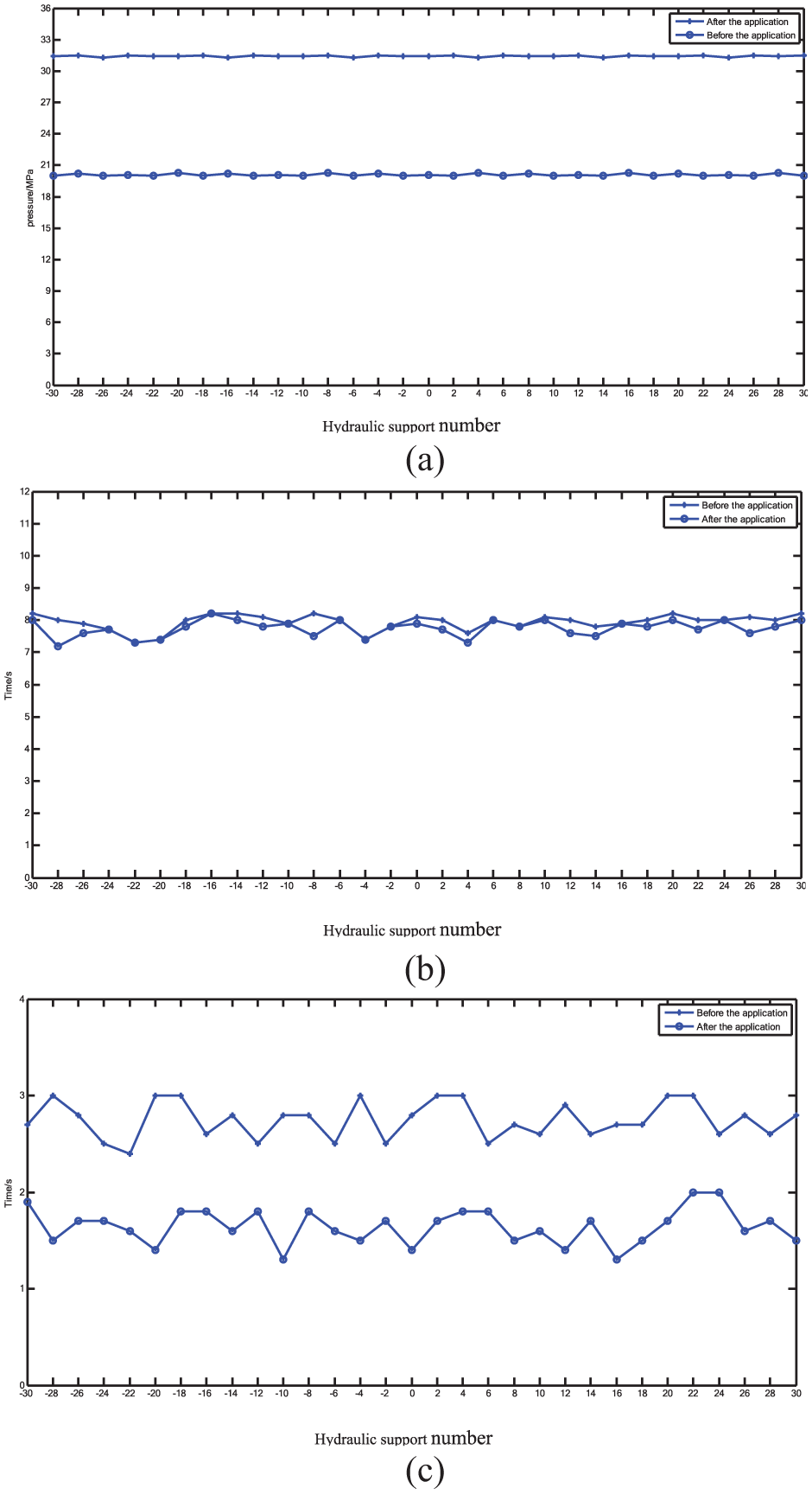
Statistical analysis of application effects: (a) initial force, (b) initial time, and (c) resistance increasing time.
Test results
The installation of the manual pressurizer significantly increased the initial supporting force (mean difference = +11.2 MPa, 95% CI 10.4–12.0, p < 0.001, Cohen’s dz = 2.1), while the initial support time remained essentially unchanged (mean difference = +0.2 s, 95% CI −0.6 to 0.9, p = 0.62, dz = 0.08). In contrast, the resistance build-up time was markedly reduced (mean difference = −14.3 s, 95% CI −15.8 to −12.8, p < 0.001, dz = 1.9), demonstrating a substantial improvement in the response efficiency of the hydraulic supports (Tables 1 and 2).
Summary of application effects.

Note. “Before application” refers to the performance of the hydraulic supports without the manual pressurizer, while “After application” denotes the measured results after the manual pressurizer was installed under the same working face conditions. The x-axis represents the hydraulic support number (0# is the central support, ±2 to ±30 are supports on both sides), and the y-axis indicates the corresponding parameter value (MPa or s).
Statistical results of application effects (mean difference, 95% CI, p value, and effect size).

The results clearly demonstrate that the manual pressurizer ensures the hydraulic supports reach their rated initial supporting force, shortens resistance build-up time, and thereby improves roof stability and operational safety.
Conclusion
This study proposes a method that integrates hydraulic and mechanical technologies to address the problem of insufficient initial supporting force in hydraulic supports.
Without altering the normal lifting function of the hydraulic support, a pressurizing control circuit was connected in parallel. Following the principle of the circuit, the device was designed with: a double-acting cylinder based on Pascal’s principle; a two-position three-way control valve to achieve simple and effective oil flow switching; a direct-acting relief valve structure for the safety mechanism; a steel ball and spring system for the one-way conduction mechanism; and a stepped valve body layout for rational integration.
Field tests demonstrated that the device significantly increased the initial supporting force of hydraulic supports to the rated value of 31.5 MPa, while also shortening resistance build-up time by 37%. The device effectively prevents premature roof separation and collapse, thereby enhancing coal mine safety.
The device is purely mechanical-hydraulic, requiring no electrical components. It is characterized by a simple structure, reliable safety, convenient installation, high stability, and strong adaptability. Its design is not limited to specific mining conditions or support types, providing broad potential for application and promotion.
Future research will focus on: Automation upgrades: integrating pressure sensing and electro-hydraulic control for automatic judgment of pressurization timing, reducing manual intervention. Versatility enhancement: developing adjustable pressurization ratio modules (e.g. interchangeable piston components) to suit supports ranging from 3000 to 15,000 kN.
Reliability improvement: conducting long-term fatigue and corrosion tests on sealing and structural components, including ceramic-coated cylinders, under harsh underground conditions (>100,000 cycles). Group control strategies: exploring coordinated initial pressurization of multiple supports using IoT technologies to achieve balanced load regulation at working faces.
Through these advancements, the proposed device offers a low-cost, reliable, and innovative solution for proactive roof control in deep coal mining. This research represents three breakthroughs: Theoretical innovation: the novel application of Pascal’s principle in proactive mining pressure control, introducing the concept of mechanical-hydraulic parallel boosting. Technical advancement: a compact step-integrated valve body combined with a dual-action booster cylinder, reducing device volume by 40% and offering a new paradigm for confined underground spaces. Practical contribution: industrial tests confirmed a compliance rate increase of initial support force from 65% to over 98%, and a 37% reduction in resistance build-up time, providing the first purely mechanical solution for preventing roof disasters in deep mining.
Footnotes
Acknowledgements
The authors would like to express their sincere gratitude to the laboratory staff of Shandong University of Science and Technology for their assistance with the experimental setup and data collection. We also appreciate the constructive suggestions provided by colleagues from the College of Mechanical and Electronic Engineering, which helped improve the quality of this study. Finally, we thank the anonymous reviewers for their valuable comments that greatly improved the clarity and rigor of this manuscript.
Handling Editor: Chenhui Liang
Author contributions
Lianmin Cao: Conceptualization, Methodology, Investigation, Writing – Original Draft. Sipeng Li: Supervision, Project Administration, Writing – Review & Editing. Zian Li: Data Curation, Software, Formal Analysis. Shilong Song: Validation, Resources, Visualization. Gao Li: Literature Review, Writing – Review & Editing, Technical Support. All authors read and approved the final manuscript.
Funding
The authors received no financial support for the research, authorship, and/or publication of this article.
Declaration of conflicting interests
The authors declared no potential conflicts of interest with respect to the research, authorship, and/or publication of this article.
Data availability statement
The datasets generated and/or analyzed during the current study are available from the corresponding author on reasonable request.