
Abstract
The causes of tooth profile concave error during shaving machining are numerous and complex, and there are strong interaction effects among the influencing factors, which leads to significant deviations between the analysis of tooth profile concave error caused by single factors and the actual results. This paper establishes a shaving meshing model incorporating axis intersection angle error. Based on shaving cutting principles, a numerical coupling method is employed to integrate the multi-source factors contributing to shaving machining errors, coupling the degree of overlap, radial feed, and axis intersection angle error into the shaving tooth profile cutting depth error at the meshing point. A stochastic algorithm-optimized genetic algorithm (SA-GA) is subsequently utilized to solve the shaving tooth profile cutting depth error. The research results indicate that when the degree of overlap ranges from 1.3 to 1.9, the radial feed ranges from 20 to 50 μm, and the axis intersection angle error ranges from 0.2° to 0.5°, the workpiece gear tooth profile’s concave error is 5.973084 μm, which is smaller than the typical range of shaving tooth profile concave error (0.01–0.03 mm). By controlling the magnitude of the shaving tooth profile cutting depth error, the shaving tooth profile concave error can be effectively reduced. This method provides a new technical approach for minimizing the tooth profile concave error.
Keywords
Introduction
Shaving still plays an important role in high-precision machining and is one of the most widely used methods for gear finishing. However, the shaving is an extremely complex process,1,2 which can lead to varying degrees of tooth surface errors. The tooth surface formation issues caused by the common “mid-concave” error phenomenon in shaved tooth profiles have yet to be effectively resolved. Current researchers, both domestically and internationally, are primarily focused on analyzing and studying the tooth concave error by examining individual factors such as the relative slip speed between the tool and gear tooth surface, the number of meshing contact points and load during shaving, the shaving cutting force, installation errors, and the degree of overlap. Lv et al. 3 studied the mechanism of shaving tooth concave error by examining three single factors: the degree of overlap during shaving, the cutting speed, and the shaving force. Specifically, he focused on the occurrence of the concave error near the pitch circle where single-point contact happens. He observed that the positive pressure between the tooth surfaces is greater in this area compared to other parts, causing the cutting edge to penetrate deeper into the tooth surface of the workpiece. Cai et al.4,5 proposed that the tooth shape accuracy of shaving processing is affected by a variety of factors such as the number of contact points during the shaving meshing, shaving pre-tooth shape error reproduction, error transmission, etc., respectively, from the control of shaving pre-gear accuracy, the amount of cutting, shaving margins to reduce the concave error in tooth shape. On this basis, the influence laws of the degree of overlap, the number of contact points and the contact point load on the contact characteristics are investigated, and an effective solution to the problem of tooth concave error is given by analyzing the relationship between the contact deformation and the tooth concave error. Chen and Tsay 6 proposed a method for calculating the tooth face load of staggered shaft helical gears with comprehensive consideration of tooth profile errors and trimming and machining manufacturing errors, and analyzed the mechanism of generating concave errors in the shaved tooth profile by the distribution of the tooth face load. Hsu and Fong7,8 studied the effect of radial shaving degree of overlap, radial feed rate and shaving force on tooth surface error by analyzing the contact state of shaved teeth machining. Cai et al.9,10 analyzed the formation mechanism of concave error in tooth shape from tooth load and contact deformation based on tooth load bearing contact analysis (LTCA) technique. Litvin et al.11,12 made contact and transmission analyses of workpiece gears and used the gear transmission method to study the shaving process. Antoniadis et al. 13 improved the cutting force model for shaved tooth machining based on an algorithm to simulate gear hobbing, analogous to the cutting force model for hobbing spur gears, which effectively improved the tooth concave error. Hung et al., 14 Wang et al., 15 and Li et al. 16 studied the effect of each parameter of the shaving machine on the tooth surface error under the consideration of the shaving installation error, and proposed an improvement method for the gear installation error. Wu et al. 17 analyzed the relative motion relationship between the shaving cutter and the workpiece gear under mounting error to study the effect of mounting error on profile shape error. Guo et al. 18 and Litvin et al. 19 through the tooth equation containing installation error and the theoretical tooth equation comparison analysis, got the machine tool each adjustment parameter error and full tooth normal deviation rule of change; through the gear tooth contact problem to analyze the gear meshing characteristics, and then put forward to improve the gear transmission performance of the effective method. Zhao et al. 20 and Peng et al. 21 studied the meshing trajectory and transmission error of helical gears under different mounting errors, and improved the transmission quality of the gears by adjusting the axial error to control the contact trajectory. Tang and Lei 22 establishes a model considering the geometrical error of machine movement and installation error, and proposes the ETCA method to study the influence law of machine movement error and installation error on the quality of tooth surface machining. Qiu and Wang 23 studied the generation mechanism of tooth shape error under the axis intersection angle error, and analyzed the influence law of spindle speed, radial feed speed, shaving cutter helix angle and axis intersection angle on tooth shape error. Cao and Li 24 established a model of helical gear considering installation error and analyzed the effect of tool parameters on tooth accuracy, and the results showed that the effect of installation error on the tooth accuracy of the shaved helical gear can be mitigated by increasing the number of teeth of the tool or reducing the axes intersection angle. Wang et al. 25 coupled the mounting error, shaving cutter parameters, and machine tool motion parameters into a single shaving volume, pointing out that too large a single shaving volume at the meshing point is the main cause of the concave error in the shaved tooth shape. Liu et al. 26 analyzed the relationship between the concave error in tooth shape and contact deformation by investigating the influence of shaved tooth overlap and tooth contact load on the contact characteristics, and gave the formation mechanism of concave error in shaved tooth shape. Chen et al. 27 analyzed the formation mechanism of concave error in shaved tooth shape from three aspects of tooth contact stress, cutting speed and induced method of curvature inequality, and put forward a solution to reduce the concave error in tooth shape in actual production.
In fact, the majority of existing studies have only explored the formation mechanism of shaving tooth profile concave error from a single-factor perspective, without considering the interactive effects of broader and more diverse coupled factors on the mechanism of tooth profile concave error. Consequently, it has been challenging to quantitatively investigate the formation patterns of tooth profile concave error, leading to significant discrepancies between the analytical results and the actual error conditions. To address these issues, this paper establishes a shaving meshing model incorporating axis intersection angle error based on gear meshing principles. Additionally, a multi-source and multi-factor numerical coupling model for the tooth profile concavity error in gear shaving is developed, which includes the degree of overlap, machine tool cutting parameters, and installation errors, based on the principle of shaving cuttings. By coupling error factors such as the degree of overlap, radial feed, and axis intersection angle error into the shaving tooth profile cutting depth error at the meshing point, the interaction effects of shaving error factors on the shaving tooth profile cutting depth error are explored, thereby investigating the formation mechanism of shaving tooth profile concave error due to the interaction effects of multi-source factors. This study provides a significant reference for addressing tooth profile concave error caused by the interaction effects of multi-source factors in gear shaving processes.
Multi-source and multi-factor coupling program
Influence factors of the concave error in shaved tooth profile
The common sources of error for concave errors in shaved tooth machining include shaved degree of overlap, shaved tooth cutting parameters, and shaved tooth installation errors.
Degree of overlap
Shaving degree of overlap is an important meshing parameter of shaving processing, which directly affects the smoothness of processing and the quality of tooth surface shaping. 28 From the shaving principle, it is evident that variations in both the shaving knife parameters and the workpiece gear parameters can alter the degree of overlap, which in turn directly impacts the meshing status throughout the shaving process. This, consequently, modifies the shaving dynamics at the contact point between the shaving elements, ultimately influencing the shaving accuracy. Therefore, instead of focusing solely on the shaving knife parameters, it is more insightful to study the impact of the degree of overlap on the shaping of the shaving tooth and the resultant concave error. By doing so, we can better understand the influence of the degree of overlap on the generation of these errors.
Radial feed
Shaving cutting parameters include spindle speed, radial feed, and axial feed. The size of shaving cutting force reflects the concave error in shaving tooth shape, 9 and the shaving cutting force directly affects the quality of the final tooth formation. The shaving cutting force is mainly determined by the radial feed, and the influence of the radial feed on the shaving cutting force significantly outweighs that of the spindle speed and the axial feed. 29 The radial feed has the greatest influence on the concave error of tooth shape, so the radial feed replaces the shaving cutting parameters to study the influence law of radial feed on the concave error of shaved tooth shape.
Axis intersection angle error
Shaving installation errors include axis intersection angle error, center distance error, and high-speed axis synchronization error. Installation errors are reflected in the tooth cut depth error, because the tooth cut depth error is directly caused by the tooth error, the smaller the axis intersection angle error, the smaller the shaving cut depth error, the impact of the axis intersection angle error on the tooth cut depth error is much larger than the impact of the center distance error. 30 The high-speed axis synchronization error is the offset error of the shaving cutter along the axis of the workpiece gear, and the offset error of the shaving cutter along the axis of the workpiece gear mainly affects the formation of tooth direction error. 31 The axis intersection angle error exerts the most significant influence on the concave error of the shaving tooth. Therefore, we will substitute the installation error with the axis intersection angle error to investigate the impact that the axis intersection angle error has on the concave error of the shaving tooth.
Modeling of shaved tooth multi-source factor coupling
It is pointed out in the Guo et al.
18
that the axis intersection angle error

Shaved tooth meshing coordinate system with axis intersection angle error.
In Figure 1,


Where:
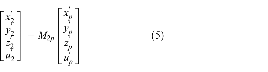
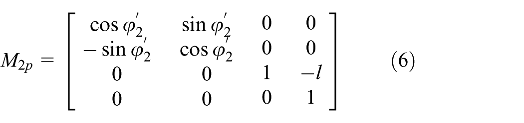
The transformation relationship between the coordinate systems


Where:
The transformation relationship between the coordinate systems
Where:
The transformation relationship between the coordinate systems


Where:
The transformation relationship between the coordinate systems


Where:
The relative sliding velocity
30

To facilitate subsequent vector calculations, the unit vectors along the x, y, and z axes of the coordinate system S (o-xyz) in Figure 1 are denoted as

Where:
In the gear shaving process, the vector expressions for the angular velocity of the workpiece gear and its axial feed velocity are as follows:

Where:
Assuming that the shaving cutter and the workpiece gear are in contact at an arbitrary point M in space, the coordinates of point M can be expressed as:

Then, the velocities of point M when it moves with the shaving cutter and the workpiece gear are respectively:

Substituting equation (15) into equation (11) yields:

From

Finally, substituting

The relative sliding velocity

Where:

The degree of overlap, radial feed, and axis intersection angle error are all crucial factors that impact the concave error in the shaved tooth profile. Based on the shaving principle, these individual factors are coupled, and the interaction effects among them are simultaneously considered to investigate the influence mechanism on the shaving tooth profile concavity error.
Degree of overlap
In order to simplify the shaving parameters, the number of teeth, helix angle, normal arc tooth thickness, effective mesh line transcendence, mesh angle, and other parameters of the shaving cutter and the workpiece gear are equivalent to the change of the degree of overlap, the design of the degree of overlap formula as shown in equation (21):

Where:
Radial feed
Among the shaving cutting parameters, the radial feed movement has the greatest influence on the shaving cutting force, and an increase in radial feed causes concave errors in the shaved tooth shape, 29 and the shaving cutting force formula is shown in equation (22):

Where:

Axis intersection angle error
Axis intersection angle error mainly affects the overall meshing state of the shaved teeth, the axis intersection angle error is positively correlated with the shaving tooth profile cutting depth error, 30 the smaller the axis intersection angle error, the smaller the shaving tooth profile cutting depth error, shaving tooth profile cutting depth error formula as shown in equation (23). Select the best axis intersection angle in shaving processing, to achieve the best shaving effect, to obtain better shaving processing quality:

Where:

Where:
The

Equation (21) is transformed to obtain the transmission ratio

Substitute equation (26) into equation (22):

From equation (27),

The relationship between the pressure angle of the tip circle end face and the normal pressure angle of the pitch circle is as follows:

Where:
According to the relationship between the center distance and the meshing angle when gears mesh as:

Where:
To express the formula concisely, substitute equation (30) into equation (23):
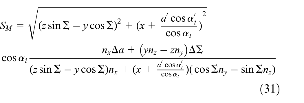
Where:
Solution of multi-source factor coupling model based on genetic algorithm
Equation (31) pertains to a single-objective optimization problem, which can be addressed using a genetic algorithm to solve the shaving tooth profile cutting depth error (

Flowchart of stochastic algorithm to optimize genetic algorithm.
Construct the initial population
Adopt binary encoding for the m shaving process parameters, and use an m-bit binary vector k to construct an individual, which represents an optimal combination of shaving parameters:

Where:
Determine the fitness function
Genetic algorithms possess robust global search capabilities and evolve only toward increasing fitness function values. Therefore, the reciprocal of the gear shaving tooth profile cutting depth error is selected as the fitness function:
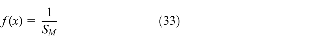
Where:
Natural selection
Natural selection is performed using a combination of the elitism method and the roulette wheel method. 33 The elitism generates k offspring individuals, while the roulette wheel selection method generates s-k offspring individuals, ensuring the offspring population size remains constant at s.
Crossover operator
Based on individual fitness, crossover recombination is performed with a probability determined by the following formula. This ensures that individuals with higher fitness have a lower probability of crossover recombination, while those with lower fitness have a higher probability. This approach preserves superior individuals and improves inferior ones in each iteration, enabling rapid and stable convergence:

Where:
Mutation operator
Similar to the crossover operator, individuals are selected for mutation based on their fitness values according to the following probability formula:

where:
Determining evolution termination conditions
The algorithm checks whether the number of iterations has reached the specified maximum T. If so, terminate evolution and select the individual with the highest fitness as the optimal solution for gear shaving error parameters when the shaving tooth profile concave error is minimized. Otherwise, the algorithm continues iteration through steps (3)–(6).
Discussion and analysis
Algorithmic solution
The material properties of the shaving cutter and workpiece gear are shown in Table 2.
Table of shaving cutter and workpiece gear material property.

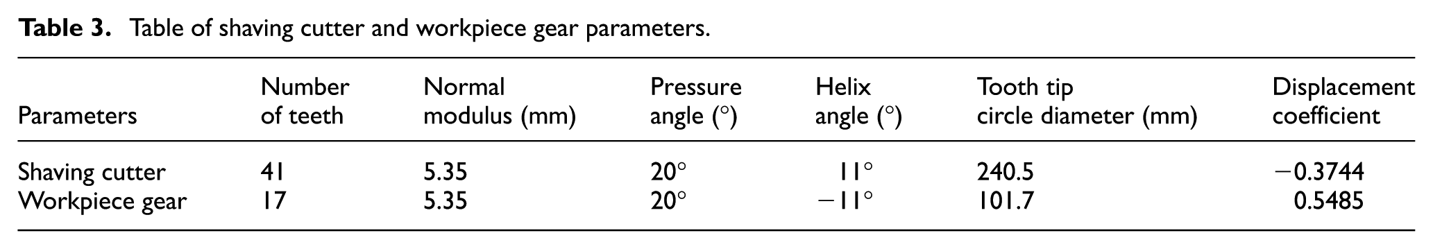
The basic parameters of the shaving cutter and the workpiece gear are shown in Table 3.
Table of shaving cutter and workpiece gear parameters.
The shaving cutting parameters selected for shaving machining according to the gear manual 34 are shown in Table 4. The displacement, angle, and speed of the machine were fine-tuned according to the actual shaving machining needs and the fine-tuned parameters were used to represent the mounting errors present in the actual shaving machining.
Shaving processing parameters.

The stochastic algorithm-optimized genetic algorithm (SA-GA) was employed to solve the shaving tooth profile cutting depth error (
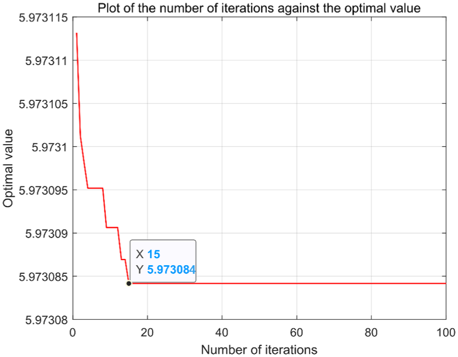
Plot of the optimal value of shaving tooth profile cutting depth error (
Finite element dynamic simulation
Since the concave shaving error often occurs in small modulus gears and shaved gears with overlap degree <2, workpiece gear parameters are selected according to the Gear Handbook, 34 and two sets of shaving cutter parameters with different overlap degrees are selected based on the Gear Cutting Tool Design and Selection Handbook, 35 as shown in Table 5. According to the shaving cutter and workpiece gear parameters in Table 5 to establish a three-dimensional model, the meshing model were imported into ABAQUS to carry out dynamic analysis as shown in Figure 4.
Shaving cutter design parameters.


Meshing model of shaving cutter and workpiece gear.
Analysis of simulation results
During the gear shaving process, the number of pairs of tooth surfaces that are simultaneously engaged between the shaving cutter and the workpiece gear varies continuously. Near the pitch circle of the workpiece gear, two pairs of tooth surfaces are engaged (single-tooth engagement), resulting in two-point contact. In contrast, at the tooth root and tooth tip regions, more than two pairs of tooth surfaces are engaged (double-tooth engagement), leading to three-point and four-point contact. The two-point, three-point, and four-point contact states in shaving meshing change in a regular pattern. To facilitate observation, the text provides a view along the end face direction of the workpiece gear. The three-point and four-point contact occurs in the double-tooth meshing zone, which is basically at the top and root of the shaved gear, and has little effect on the concave error in the shaved tooth shape. For the study of reducing the concave error of shaved tooth shape, this paper focuses on analyzing the single-tooth meshing with two-point contact. The shaved tooth meshing simulation of Section 3.2 is shown in Figures 5 and 6.

Meshing contact stress cloud of shaving process: (a) two-point contact, (b) three-point contact, and (c) four-point contact.

Meshing displacement cloud of shaving process: (a) fractional displacement in the X-direction, (b) fractional displacement in the Y-direction, (c) fractional displacement in the Z-direction, and (d) total displacement magnitude.
Stress cloud diagram
The concave error of the shaved tooth profile originates from excessive removal of metal at the pitch circle position in the single-tooth engagement zone. The underlying cause is that when the shaving process occurs in the single-tooth engagement region, the contact surfaces at the mid-section of the workpiece gear tooth profile is reduced, leading to higher localized loading and increased cutting depth by the shaving cutter. As the workpiece gear rotates, the excessive metal removal in this region accumulates, resulting in the formation of a concave tooth profile. Figure 5(a) illustrates that the contact points on both the left and right tooth flanks are located near the pitch circle region of workpiece gear, where the maximum contact stress in the two-point contact zone is 6.618 × 10⁸ Pa. In Figure 5(b), the maximum contact stress in the three-point contact zone is 6.569 × 10⁸ Pa, while in Figure 5(c), the maximum contact stress in the four-point contact zone is 6.441 × 10⁸ Pa. These results indicate that the contact stress at the pitch circle is higher than that at the tooth tip and root regions.
Displacement cloud diagram
Existing studies have indicated that the phenomenon of tooth profile concave error is not significant in the three-point and four-point contact areas. Consequently, the displacement variation at the mid-section of the tooth profile in these contact zones is negligible and thus not discussed in detail. From the displacement cloud Figure 6(d), it is shown that the maximum total displacement in the two-point contact zone near the pitch circle region is 1.860 μm, which is small compared with the displacement at the top of the tooth, indicating a minor concave deformation in the tooth profile near the pitch circle. In the process of gear meshing by shaving, the amount of tooth mid-pitch error is mainly reflected in the sub-displacement in the x-direction, as shown in Figure 6(a), followed by the sub-displacement in the y-direction, as shown in Figure 6(b), and the smallest sub-displacement in the z-direction, as shown in Figure 6(c). The magnitude of the tooth surface displacement concavity directly indicates the amount of metal removal at the mid-section of the tooth profile; a smaller displacement concavity corresponds to less metal removal.
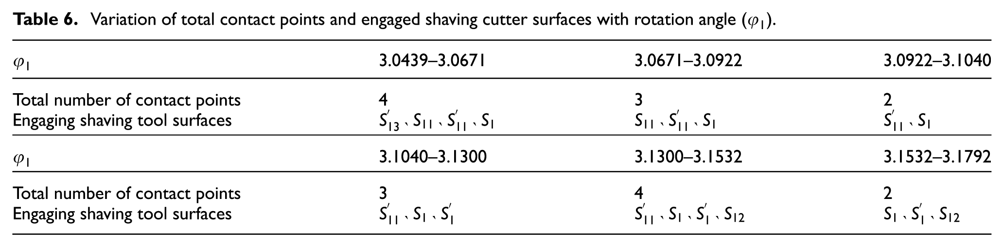
When analyzing the influence of contact stress and displacement variations on the concave error in tooth profiles, it is necessary to establish a schematic diagram of the shaving tooth surface meshing, as illustrated in Figure 7. When the shaving cutter surface

Schematic diagram of tooth surface meshing.
Variation of total contact points and engaged shaving cutter surfaces with rotation angle (
Based on the simulation results of contact stress and displacement in Figures 5 and 6, the maximum stress values and contact deformation magnitudes at each point for two-point, three-point, and four-point contact were sequentially extracted from the post-processing module of the finite element simulation software ABAQUS. Subsequently, the maximum stress values and contact deformation magnitudes were correlated with their respective instantaneous time points to generate the contact stress curves and contact deformation curves, as illustrated in Figure 8. In the figure, Δ-2, Δ-3, and Δ-4 represent the maximum stress range values for two-point, three-point, and four-point contact, respectively.

(a) Relationship between contact stress (
Shaving involves the shaving cutter and the workpiece gear engaging in a backlash-free motion. Throughout the entire shaving process, point contact exists between the shaving cutter and the workpiece gear. Under the action of the radial force, contact stress is generated at the contact point. The magnitude of the radial force directly influences the magnitude of the contact stress; the greater the radial force, the greater the contact stress.29,36 Shaving is a process of extrusion cutting, where the load between the contacting tooth surfaces is provided by the radial force, which can be considered essentially constant during each cycle of processing. At the pitch circle, there is two-point contact, with fewer contacting tooth surfaces. Therefore, the radial force borne by each contact point is larger, resulting in higher contact stress and greater load. This causes the shaving cutter to remove more metal, which can easily lead to a concave tooth profile error. Hence, as clearly observed in Figure 8(a), the contact stress at the pitch circle is higher than that at the tooth root and tooth tip.
The magnitude of contact force is the primary factor influencing contact deformation. According to Hertzian theory, 37 the indentation – that is, the value of contact deformation – increases with the rise in contact stress. Similarly, when the contact deformation increases, the contact stress may concentrate in certain regions, leading to further amplification of errors in those areas. At the pitch circle, where the number of contact points is minimal, the contact stress is higher. Consequently, the tooth surface indentation at this location is more pronounced during the cutting process, leading to a greater concavity in the shaved tooth profile.
Based on the simulation data of contact stress at the pitch circle shown in Figure 8(a), and in accordance with equation (19), the variation of shaving force with contact stress, radial feed, and degree of overlap was calculated as shown in Figure 9(a). Additionally, following equation (23), the variation of shaving tooth profile cutting depth error (
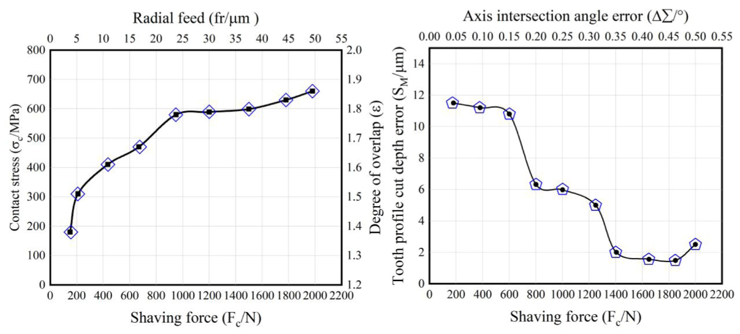
(a) Influence relationship diagram of
Based on the information presented in Figure 9, it is known that when the degree of overlap ranges from 1.3 to 1.9, the radial feed is within the range of 20–50 μm, and the axis intersection angle error is between 0.2° and 0.5°, the shaving tooth profile cutting depth error (
Instance validation
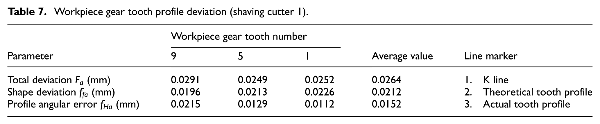
Using the shaving cutter with the parameters shown in Table 5, the workpiece gears are test shaved on Y4236 shaving machine. Apply the universal gear measuring instrument GM3040a on the shaved workpiece gears for tooth shape and tooth direction detection, select three of the workpiece gears on the left side of the tooth profile, the results are shown in Tables 7 and 8 and Figure 10.
Workpiece gear tooth profile deviation (shaving cutter 1).
Workpiece gear tooth profile deviation (Shaving cutter 2).


Shaving tooth profile and direction detection.
The shape deviation of tooth profile is determined by the highest and lowest points on the actual tooth profile trajectory, and the shape deviation of tooth profile can be used as an evaluation parameter to measure the concave error in tooth shape. 30 From Figure 10, it can be seen that the shaving effect of shaving cutter 2 with a design overlap of 1.7712 selected for trial shaving is more satisfactory than that of shaving cutter 1 with an overlap of 1.8294. The reason for doing so is to enhance the degree of overlap, thereby increasing the meshing line of the double teeth mesh area, balancing the force distribution at the mesh contact points, stabilizing the transmission during the shaving process, and ultimately improving the quality of tooth formation. However, when the degree of overlap increases to a certain extent, continue to increase the degree of overlap will increase the shaving cutter and the workpiece gear meshing local contact point force, resulting in shaving and meshing process is not smooth, vibration, resulting in a larger tooth shape on the tooth surface concave, manifested as tooth “concave” error. The shaved gears in the workpiece will exhibit varying degrees of tooth concavity errors when there is an axis intersection angle error. As the axis intersection angle error increases, the tooth concavity error also increases. Radial feed movement on the shaving cutting force has the greatest influence, shaving force is large, easy to form tooth surface error. Following tooth shape detection, the results indicate that at the pitch circle position (with a pressure angle of 0.3653), the average tooth profile deviation is 9.2 μm when the axis intersection angle error is 0.2° and the radial feed is 0.03 mm. In contrast, when the axis intersection angle error is 0.5° and the radial feed is 0.045 mm, the average tooth profile deviation at the same position increases to 21.2 μm. Shaved teeth processing tooth concave error value of 10–30 μm, combined with the actual processing needs, the choice of shaved teeth processing parameters overlaps 1.7712, axis intersection angle error of 0.2°, radial feed for 0.03 mm, can significantly reduce the shaved teeth tooth concave error.
Conclusion
The sources of tooth concave error involved in gear shaving include the degree of overlap, machine tool cutting parameters, and installation error. Taking into account the impact on the shaved tooth concavity error, based on the principles of shaving cutting, the individual factors of overlap, radial feed, and axial intersection angle error are integrated into the shaved tooth depth of cut error at the meshing point. The SA-GA algorithm is employed to solve for the shaved tooth depth of cut error, yielding the value range of the coupling factors that minimize this error. According to the value range to try to shave the workpiece gear, the amount of concave error in the workpiece gear tooth shape is reduced by nearly 10%. At the same time, it also provides a basis for the accurate selection of shaving cutter and workpiece gear design parameters in the process of shaving processing. The establishment and application of a multi-source and multi-factor coupling method for shaving processing addresses the issue of inaccurate analysis results that arise when examining the mechanism of tooth concavity error solely from a single-factor perspective. This method offers a novel analytical approach for understanding the multi-factor coupling in shaving processing.
Footnotes
Handling Editor: Chenhui Liang
Funding
The authors disclosed receipt of the following financial support for the research, authorship, and/or publication of this article: This work was financially supported by the Key R&D Program of Shaanxi Province (grant no. 2023-YBGY-095).
Declaration of conflicting interests
The authors declared no potential conflicts of interest with respect to the research, authorship, and/or publication of this article.