
Abstract
This paper establishes a thermal analysis model for parametric profile modification gears based on the heat transfer mechanisms of gear transmission. The main research parameters are the addendum coefficient and the modification coefficient, focusing on the spatial distribution of frictional heat flux and the gear body temperature field. The study analyzes the effects of two different methods of parametric profile modification on thermal characteristics. The results indicate that reducing the addendum coefficient can improve thermal characteristics, effectively lowering both the amplitude and gradient of the tooth surface temperature. Conversely, a decrease in the modification coefficient increases the tooth surface temperature and leads to a more uneven spatial distribution of the temperature field in the gear body, thereby deteriorating its thermal characteristics. A sensitive interval for the influence of tooth profile modification parameters on thermal characteristics is proposed, establishing an intuitive connection between tooth profile modification parameters and the thermal characteristics of gears, which provides theoretical support for the parametric design method of thermal tooth profile modification.
Keywords
Introduction
During the process of gear transmission, its thermal characteristics are primarily manifested in the uneven temperature field formed by the substantial heat generated from friction, which leads to failures such as wear, pitting, and scuffing of the gears.1,2 Additionally, changes in temperature also affect the friction performance of gear transmission, with varying impacts depending on different types of gear oils. 3 Experiments have demonstrated that different lubrication methods, such as oil immersion and oil spraying, have distinct effects on engagement efficiency, gear temperature, and surface roughness. 4 Zhou et al.5,6 improved the structural design of gear transmission to increase oil film thickness and oil film pressure, which reduced the temperature rise of hydraulic oil and effectively prevented wear failures in high-speed gear pumps. Different tooth profiles lead to temperature field differences under unlubricated conditions, it can affect the power transmission efficiency of gears. A typical case is that, under unlubricated conditions, sinusoidal gears have lower tooth surface temperatures and higher power transmission efficiency compared to involute gears. 7
When the material strength of the gears is insufficient, it is necessary to consider the failure due to tooth breakage caused by temperature rise. Takahashi et al. 8 conducted lifetime experiments on plastic gears and measured the temperature of meshing teeth in response to this situation. The temperature field of the gears mainly includes the body temperature and flash temperature. Preliminary calculations indicate that flash temperature is confined to materials below the surface (5–10 microns) and decays within a fraction of the rotation speed. Therefore, for most of the time during each rotation, the surface temperature of the gears will be close to the body temperature.9,10 To measure the actual operating temperature of gears, researchers have proposed various methods for measuring gear temperatures. Installing thermocouples within the gear body can accurately and real-time measure the temperature during gear transmission; however, the disadvantage is that this requires drilling holes in the gears, which alters the gear’s structure and cannot ensure that the temperature of the drilled gear is completely consistent with that of an undamaged gear. 11 Infrared temperature measurement devices (such as infrared thermometers and thermal imaging cameras) can measure the temperature of gears without contacting the gear body. Although they can not monitor temperature changes during the testing process, they can evaluate the thermal characteristics of gear transmission through the average temperature at the meshing point.12,13 To enhance the accuracy of infrared temperature measurement methods, Chang et al. 14 proposed an indirect temperature measurement method for spur gears, where they first identified target measurement positions with the same temperature distribution as that of direct measurement locations, and then analyzed the temperature difference between these target positions and the direct measurement locations using finite element methods.
Many studies have shown that the temperature of the gear body is closely related to scuffing and wear failure. Chen et al. 15 effectively established a gear temperature model using a sequential coupling numerical method, discovering that gear scuffing failure is associated with the increase in tooth surface temperature, this process accompanied by the elevation in gear body temperature. In the calculation of the heat transfer formula for gear body temperature, the gear body temperature is closely related to the frictional heat flux. 9 Zhou et al. 6 proposed that body temperature is a critical component of contact temperature, predicting gear body temperature through a thermal network model, and corrected the wear model by replacing environmental temperature with the predicted body temperature. The results of the model indicate that body temperature significantly impacts wear failure. Koffel et al. 16 conducted overall temperature measurements on gears using the FZG test bench, confirming that the gear body temperature is closely related to wear failure. Castro and Seabra 17 defined the concept of critical mass temperature wear, a new wear parameter proposed based on mineral-based lubricated gears, primarily aimed at calculating the critical temperature of other similar oils, thus reducing experimental costs. It is important to note that excessively high temperatures can also affect material properties such as elastic modulus and Poisson’s ratio, subsequently impacting the dynamic characteristics of the gear system.18,19
In summary, by studying the thermal characteristics of gears during the gear transmission process, including temperature and frictional heat flux, we can further analyze the thermal failures such as scuffing and wear caused by temperature rise, which holds significant importance for researching gear failure behavior. The investigation of the thermal properties of gears also leads to effective methods for reducing gear temperature, thus preventing potential thermal failures like scuffing and wear. Consequently, many scholars have researched the thermal characteristics of gears, utilizing mainstream methods such as analytical methods, finite element methods, and thermal network methods. The analytical method involves establishing a nonlinear dynamic model for the entire system, where the effects of temperature and thermal deformation are represented as functions, allowing the assessment of the overall dynamic characteristics.20,21 The thermal network method typically replaces the complete spur gear with a single tooth, establishing a thermal network model on the gear tooth and setting multiple temperature nodes to investigate the thermal characteristics of the gear. These temperature nodes are connected through thermal resistance due to heat conduction, while they are also connected to the environment via convective heat transfer resistance. 6 By appropriately setting heat sources, the temperature field distribution of the gear can be calculated quickly, facilitating the study of its friction behavior and wear failure.5,16
The finite element method (FEM) requires relatively long computation time; however, it yields more accurate results and provides a more intuitive representation of the temperature field distribution in three dimensions. The increase in frictional heat and the temperature of the meshing teeth are closely related, but there is still no conclusion on whether the gear temperature can be directly assessed from the frictional heat. Therefore, it is necessary to first calculate the frictional heat flux and the convective heat transfer coefficient at the tooth surface under different meshing positions, and then establish the temperature field model of the gear body using FEM.8,22 In finite element analysis, since the heat transfer processes of each tooth are identical, a single tooth model is adopted to reduce computation time. 23 Furthermore, the results obtained from FEM can simulate both the spatial distribution and temporal evolution of the gear temperature field, leading to a comprehensive analysis of gear thermal characteristics.24,25 Thus, the most effective approach for researchers remains to use the finite element method to study the thermal characteristics of gears and their influencing factors.
However, in previous studies, there has been relatively little research on the impact of tooth profile on the thermal characteristics of gears, with only a few scholars conducting relevant investigations in this area. Li et al. 26 examined the influence of profile modification on the thermal characteristics of gears, concluding that modification can reduce temperature rise, thereby enhancing resistance to scuffing failure and preventing gear seizure. Fernandes et al.27,28 investigated the effect of tooth profile on thermal characteristics, suggesting that the tooth profile can be optimized by altering the modulus and the number of teeth to lower the temperature of the gear body. However, there are still many parameters in gear design that can effectively change the tooth profile, thereby affecting the thermal characteristics of the gears. This study finds that appropriately altering the modification coefficient and the addendum coefficient can produce a similar profile modification effect on gears. Therefore, further research is needed to undertake a comprehensive investigation into the effects of these two parametric modification methods on the thermal characteristics of gears. This research should not only quantify the changes in temperature distribution across the gear surfaces but also explore the underlying mechanisms that allow these modifications to influence heat flux and dissipation. In particular, it is crucial to assess whether these methods can effectively optimize the temperature field in diverse operational conditions, thereby preventing conditions that lead to scuffing failure, overheating, and a range of thermal failures. Such failures, which may include microstructural degradation and premature wear, can significantly impair gear performance and lifespan. The influence of thermal characteristics is obtained by comparing the frictional heat flux and the temperature field distribution of the gears under two different methods. Based on this, an evaluation of the impact of these two different parametric modification methods on the thermal characteristics of gears is conducted.
Analysis of influence factors of parametric thermal tooth profile modification model
In gear transmission systems, due to the frictional heat generated by the gear teeth, an uneven temperature field is produced within the gear body. The gear body temperature field affects the meshing performance of the gear system and is a major cause of tooth thermal failure, making it a key aspect in the study of gear thermal characteristics. During the gear meshing process, the frictional force on the tooth surfaces does work to generate heat. Part of this heat is conducted into the interior of the gear, while another part is removed via convective heat transfer under the influence of the lubricant. Based on Fourier’s law and the law of conservation of energy, a differential equation for heat conduction in the gear transmission system varying with time and space is established.

In the equation, t represents temperature,

The steady-state temperature field of the gear is solved by determining the boundary conditions during thermal equilibrium based on Newton’s cooling law and Fourier’s law. The expressions for the boundary conditions on the non-engaging surfaces, the tooth root, and the tooth tip are:

The expression for the boundary conditions at the gear engaging surfaces is:

In the equation,
Frictional heat flux of the gear
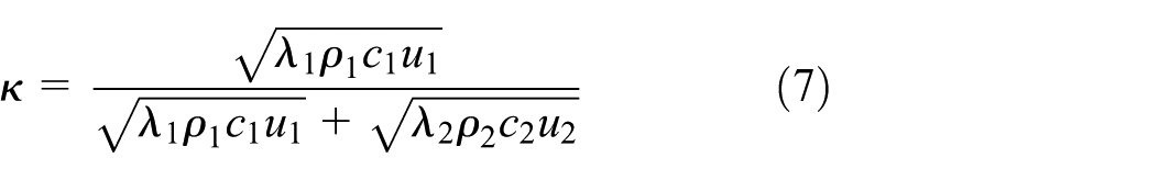
Heat is generated at the contact points of two gears due to friction, and the heat produced per unit time per unit area is referred to as heat flux. The pressure at the two contact points is denoted as p, which can be obtained through Hertzian contact theory. The coefficient of friction is represented by f, which is typically approximated as 0.06. The ratio of friction work converted into heat is denoted by

The total frictional heat flux generated over a cycle is:

In the equation, u represents the tangential velocity at the tooth meshing point, with subscripts 1 and 2 denoting the driving gear and the driven gear, respectively.
The total frictional heat flux generated by the driving gear and the driven gear is:

In the equation,
In the calculation process of body temperature, the average frictional heat flux during the meshing period is applied, during the driving gear meshing period, the average frictional heat flux is:

The geometric parameters of standard gears studied in this section is presented in Table 1, while the material parameters and operating condition parameters are shown in Table 2.
The geometric parameters of standard gear.

The material parameters and operating condition parameters of standard gear.

Convective heat transfer coefficient of the gear
The gear system primarily dissipates heat to the external environment through convective heat transfer with lubricant and air. The effectiveness of convective heat transfer depends on the parameters of the gears and the lubricant (thermal conductivity, viscosity, density, specific heat capacity, etc.), the fluid flow regime (laminar or turbulent), and the flow driving mechanism (natural convection or forced convection). Relevant parameters are shown in Table 3.
The parameters of lubricant.

In gear system lubrication, oil mist lubrication is typically employed, with the lubricant covering the tooth surface and side face. At the start of operation, the lubricant temperature is equal to room temperature; however, as the operation time increases, the temperature of the lubricant gradually rises until it stabilizes at a thermal equilibrium state. The convective heat transfer between the gear teeth and the coolant can be simplified into three models, namely, convective heat transfer at the tooth surface, side face, and addendum.
1. The convective heat transfer coefficient of the tooth surface
The convective heat transfer coefficient between the tooth surface and the lubricant can be determined by the following formula:

In the formula,
The convective heat transfer coefficient of the addendum
2. The convective heat transfer of the lubricant and the addendum can be simplified to the convective heat transfer of the lubricant flowing over a long flat plate. The convective heat transfer coefficient is determined by the following formula:

In the formula,
3. The convective heat transfer coefficient of the side face
The convective heat transfer of the side face can be simplified to the convective heat transfer of a rotating disc. The flow regime can be classified into laminar, transitional laminar, and turbulent based on the Reynolds number of the lubricant. The calculation of the convective heat transfer coefficients for these three flow states is shown in the following formulas:

In the formula, m is the exponent constant, with a value of 2 due to the radial distribution of temperature on the gear side face. Under actual operating conditions, the convective heat transfer from the gear side face is treated as a two-phase convective heat transfer involving a mixture of air and lubricant. Taking into account the influence of the gear side face radius and actual operating conditions on the convective heat transfer coefficient, the mixed flow of lubricant and air is regarded as a mixed fluid, leading to modifications in the formula. The performance parameters of the mixed fluid are calculated using the following equation:
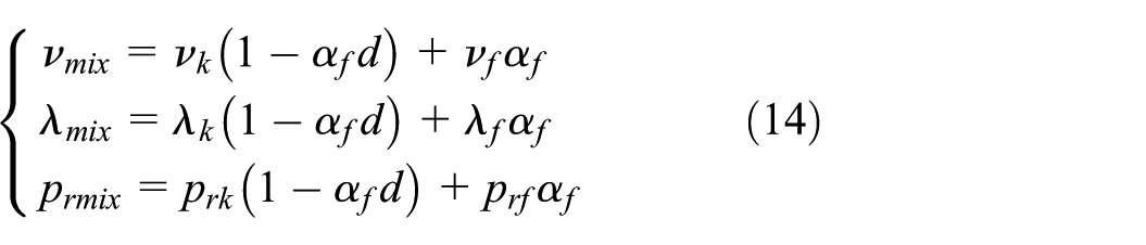
In the equations,
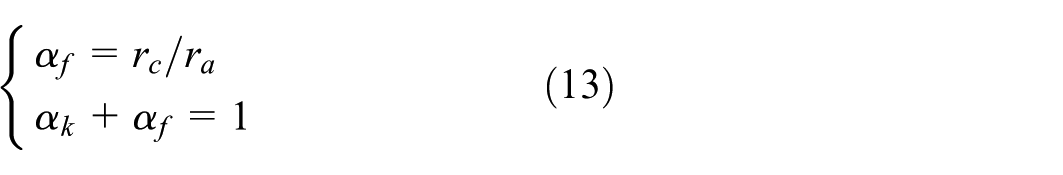
Tooth profile modification parameters of the gear
By modifying the modification coefficient and the addendum coefficient, it is possible to achieve the effect of profile modification simply by adjusting the parameters. This approach can effectively simplify the profile modification process and reduce production costs, hence these two parameters are considered the main parameters for profile modification. Under the condition that the center distance and other parameters remain unchanged, this study investigates the impact of varying the modification coefficient and the addendum coefficient on the tooth profile. In the standard state, the addendum coefficient

Schematic diagram of gear tooth profile.
From Figure 1, when

Frictional heat flux in the tooth profile direction.
For the driving gear, the engaging-out region is located near the tooth tip, while the engaging-in region is situated near the tooth root. According to Figure 2, the frictional heat flux is maximized at the engaging-in region of the driving gear, followed by the engaging-out region, with abrupt changes occurring at the alternating single and double teeth, and the frictional heat flux being minimal near the pitch circle. The tooth profile primarily affects the spatial distribution and maximum value of the frictional heat flux along the tooth profile, thereby influencing the thermal characteristics of the gear. Therefore, it is necessary to study the direct effects of different parameters on the frictional heat flux. To make the results more intuitive, the length of the meshing area is non-dimensionalized, represented by the dimensionless quantity

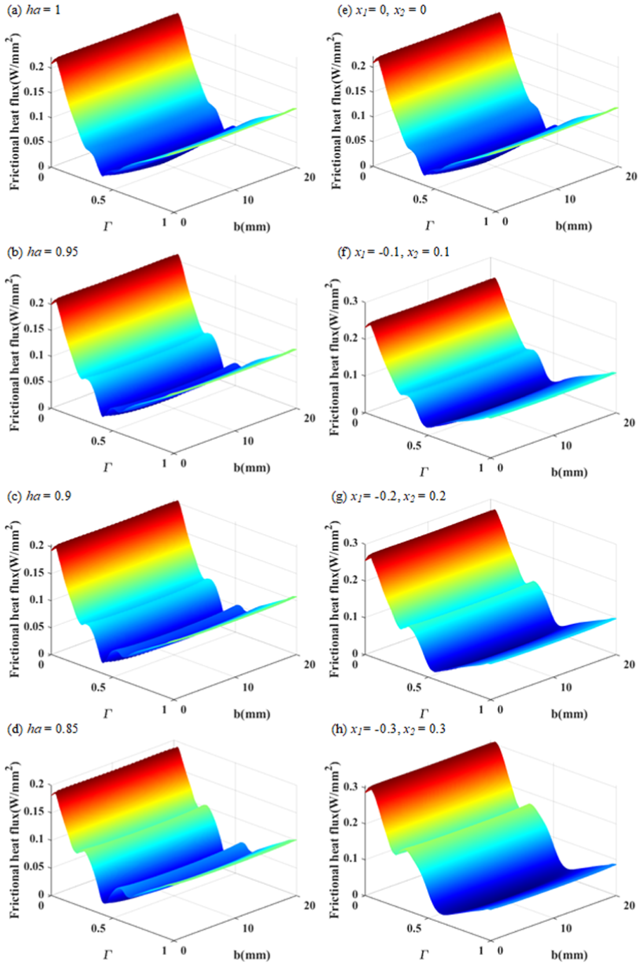
Frictional heat flux at different addendum coefficients and modification coefficients.
In Figure 3(a) to (d) represent the frictional heat flux under different addendum coefficients
Analysis of thermal characteristics of gear body
Under the condition of thermal equilibrium, each tooth in operation experiences the same repetitive frictional heat flux and heat transfer, including frictional heat generation at the tooth surface, convective heat transfer at the tooth surface, and thermal conduction within the tooth body. Therefore, a parametric finite element model of a single tooth has been established for analysis.
Parametric finite element model establishment and boundary condition analysis
When establishing a finite element model for the analysis of the temperature field in gears, it is necessary to apply the frictional heat flux and convective heat transfer boundary conditions. Traditionally, an average frictional heat flux has been directly applied to the tooth surface, resulting in a completely uniform distribution of frictional heat flux across the tooth surface. However, considering that the spatial distribution of frictional heat flux on the actual tooth surface exhibits certain regular variations, improvements have been made to the conventional finite element model in order to more effectively compare the effects of different modification parameters on thermal characteristics. Nodes are divided along the tooth width and the direction of the tooth profile on the engaging surface, with corresponding frictional heat flux applied to each node. The application of the frictional heat flux and convective heat transfer boundary conditions in the finite element model is illustrated in Figure 4.

The application of boundary conditions of the finite element model.
In Figure 4(a) to (c), the green areas represent the spatial application of the convective heat transfer coefficients for the tooth tip, side face, and tooth surface regions, while the blue line in Figure 4(d) illustrates the spatial application of frictional heat flux. Under different parameter conditions of addendum coefficients and modification coefficients, both the tooth profile and frictional heat flux have changed. To analyze the temperature field of the gear more accurately, it is essential to consider the coupling effects of these two aspects simultaneously. The changes in the tooth profile are reflected in the three-dimensional gear model, while the variations in frictional heat flux are represented numerically by substituting specific values into the finite element model. The distribution of frictional heat flux under different addendum coefficients is shown in Figure 5, and the distribution of frictional heat flux under different modification coefficients amounts is illustrated in Figure 6.

Spatial distribution of frictional heat flux under different addendum coefficients.

Spatial distribution of frictional heat flux under different modification coefficients.
As shown in Figures 5 and 6, the finite element model considers the spatial distribution of frictional heat flux across the entire tooth profile. The frictional heat flux on the engaging surface is uniformly distributed along the tooth width direction, and the spatial distribution trend in the direction of the tooth profile is consistent with the calculated trend. The maximum frictional heat flux occurs near the tooth root, followed by the tooth tip, while the minimum is at the pitch circle. The values of frictional heat flux at other positions are negligible, which aligns with the actual working conditions of the gears, indicating that the established finite element model is reasonable. The focus of the research is on the frictional heat flux on the engaging surface. After extracting the data of frictional heat flux on the engaging surface and normalizing it in the tooth profile direction, the results are presented in Figure 7.
Spatial distribution of frictional heat flux under different tooth profile modification parameters.
When
Frictional heat flux under different addendum coefficients

Frictional heat flux under different modification coefficients

Gradient of frictional heat flux under different addendum coefficients

Based on the frictional heat flux of the standard state of the gear, analyzing the rate of change of the relevant numerical values of the frictional heat flux after profile modification. According to Table 4, both the maximum and average values of the frictional heat flux decrease as
The reduction rates of the maximum values being 4.58%, 8.06%, and 14.80%, while the reduction rates of the average values are 2.21%, 5.11%, and 5.76%, indicating that the maximum value maintains a stable reduction rate, while the reduction in the average value is gradually decreasing. This suggests that as
According to Table 5, both the maximum and average values of the frictional heat flux increase as the displacement coefficient
Gradient of frictional heat flux under different modification coefficients

The growth rates for the maximum values are 11.56%, 24.12%, and 38.32%, while the growth rates for the average values are 5.96%, 15.38%, and 32.61%. To investigate the fluctuations of the frictional heat flux, the rate of change of the difference between the maximum and minimum values was also analyzed, yielding growth rates of 10.26%, 23.81%, and 34.56%. This indicates that the decrease of
The numerical values and trend variations of the overall spatial distribution of frictional heat flux obtained through the finite element model are compared with the theoretical calculation. The results of both approaches are highly consistent in terms of trends, although there is a certain discrepancy in numerical values. This discrepancy is primarily reflected in the maximum value, mean value, and the difference obtained by subtracting the minimum value from the maximum value. To quantify this analysis, the corresponding errors between the results are calculated based on the outcomes of the finite element model. The analysis of the process in which
The analysis of the numerical discrepancies reveals that the finite element model takes into account the influence of the tooth profile variations. It incorporates more influencing factors beyond the theoretical calculation values and conducts a more precise coupling analysis. As a result, the outcomes obtained are closer to actual conditions. A comprehensive comparison between the theoretical calculations and simulation results under different states reveals that the differences in extremum comparisons are relatively small, indicating that the distribution trend of theoretical frictional heat flux and the sensitive parameters are also close to actual conditions and can be applied directly. However, there is a notable discrepancy in the average value results. This can be addressed by continually iterating on the theoretical algorithm and performing surface fitting on the multiple sets of data obtained after iteration, in an attempt to approximate the finite element method and reduce errors. Overall, the results derived from the theoretical calculation method correspond well with those obtained from the finite element method, and can effectively calculate the frictional heat flux under actual working conditions. The theoretical calculated values can quickly provide accurate boundary conditions for the gear thermal characteristic analysis model.
Analysis of gear body temperature field under different profile modification parameters
A three-dimensional finite element model considering heat conduction and convection was established, incorporating boundary conditions of frictional heat flux to solve the temperature field of the gear body, ultimately obtaining results under stable operating conditions. The temperature field of the gear body with different addendum coefficients is shown in Figure 8, and the temperature field with different modification coefficients is illustrated in Figure 9.

Body temperature field under different addendum coefficients.

Body temperature field under different modification coefficients.
From Figures 8 and 9, it can be observed that the spatial distribution trend of the temperature field in the standard gears and the modified gears is similar, with high-temperature regions concentrated at the engaging surfaces and lower temperatures elsewhere. An analysis of the temperature field at the engaging surface reveals a symmetrical distribution along the tooth width direction, where the temperature reaches its peak in the central region of the engaging surface near the gear teeth, decreasing towards both side faces. In the tooth profile direction, two distinct temperature peaks are identified, with the highest temperature occurring close to the tooth root and the lowest near the pitch circle, corresponding to the positions of maximum frictional heat flux. The locations of the maximum and second maximum values of temperature and frictional heat flux do not completely align, which can be attributed to various factors affecting the heat transfer situation at the engaging surfaces of the gears, including the spatial structure of the tooth shape. Therefore, establishing a finite element model of the temperature field is necessary to ensure that the temperature solution results are closer to the actual operating conditions.
The temperature of the engaging surface is a crucial component of the overall temperature during the gear transmission process, significantly impacting the anti-scuffing bearing ability of the gear system. The purpose of profile modification is to improve the thermal behavior during the gear transmission process; thus, reducing the temperature of the engaging surface is a direct manifestation of its effectiveness. Particularly at the locations near the tooth tip and root on the engaging surface, where the contact pressure is high, there are impacts during engagement and disengagement, making these areas prone to temperature peaks and susceptible to thermal failures such as scuffing failure. Therefore, the temperature field of the meshing surface in Figures 8 and 9 is extracted, and the temperature field under different parameter conditions is compared, as shown in Figure 10.

The bulk temperature field of gear under different tooth profile modification parameters.
As
Engaging surface temperature under different addendum coefficient
Engaging surface temperature under different modification coefficient
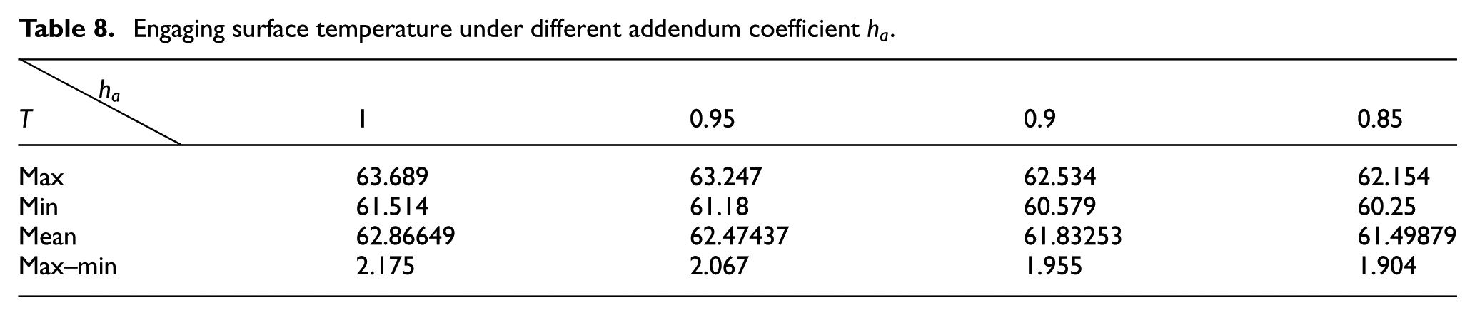
Based on the temperature field of the gear body in the standard state, the analysis focuses on the rate of change of relevant temperature values after profile modification. According to Table 5, both the maximum and average temperatures decrease as
Gradient of engaging surface temperature under different addendum coefficients

The maximum value of temperature decreases by 0.69%, 1.81%, 2.41%, the minimum value decreases by 0.54%, 1.52%, 2.05%, and the average value decreases by 0.62%, 1.64%, 2.18%. Under the equal step change of
Therefore, it is believed that reducing
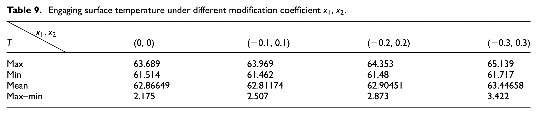
According to Table 9, as the modification coefficient
Gradient of engaging surface temperature under different modification coefficients

The rate of change for the maximum temperature is 0.44%, 1.04%, and 2.28%, while the rates for the minimum temperature are −0.08%, −0.06%, and 0.33%. The rates for the average temperature are −0.09%, 0.06%, and 0.92%. This indicates that with the continuous decrease of
Although reducing the parameters
The thermal characteristics of gears are significantly influenced by the profile modification parameters. A parametric profile modification finite element model can be established to directly obtain the results of the temperature field of the gear body as the parameters change. This further analysis reveals the impact on thermal characteristics, providing an intuitive reflection of the relationship between parameter changes and their effects on thermal properties, thus laying a foundation for the study of gear thermal failure behavior. This model can consider the comprehensive effects of profile modification parameters on input boundary conditions, reflecting the changes in both numerical and spatial distribution trends of the gear body’s temperature field. It offers timely qualitative analysis on how parameter changes affect thermal characteristics, confirming whether the profile modification effect leads to positive optimization or negative impacts. By combining data post-processing analysis, regions with significant parameter influences can be identified. It can pinpoint hazardous ranges that negatively affect thermal characteristics, such as when
Experimental verification
To verify the accuracy of the established model, tests were conducted using the FZG gear testing rig, as shown in Figure 11. The module of the driving gear and driven gear in the experimental gear pair is 6 mm, the pressure angle

FZG gear temperature test bench.
Two different operating conditions were considered, with loads of 1.13 and 3.01 kW, and rotational speeds of 300 and 600 r/min. Under each condition, the test gear was operated on the test rig for 10 min until it was assumed to reach a steady state. Immediately after a 10-s shutdown, measurements were taken to ensure that minimal heat dissipation occurred from the gear and that the gear body temperature remained close to the operating temperature. An infrared thermometer was used to take measurements at three fixed points along the tooth profile—from the tooth tip to the tooth root—based on the previously observed spatial temperature distribution trend, and the average temperature was calculated. The parameters of the operating conditions and the experimental results are shown in Table 12, while the finite element analysis results are presented in Figure 12.
Experimental results.


Solution results of finite element model.
Taking the experimental results as a baseline, a comparison was made between the finite element model solutions and the experimental results, focusing on the error of the temperature extremes. The maximum and minimum error values under the two operating conditions were 4.13%, 5.02%, 1.57%, and 1.69%, respectively, with errors being maintained within 10%, thereby validating the accuracy of the finite element model.
Conclusion
This paper utilizes numerical solutions and finite element methods to compute the frictional heat flux through numerical analysis. By combining the finite element automatic programming language APDL, a parameteric tooth profile modification thermal analysis model is established. The addendum coefficient and the modification coefficient are defined as the main modification parameters, and the direct impact of these parameters on the thermal characteristics of the gear is analyzed. The conclusions are as follows:
Based on the theoretical analysis results of the two-dimensional frictional heat flux, combined with the three-dimensional actual boundary conditions and finite element model, the variation of the frictional heat flux in gear teeth under the influence of profile modification parameters has been obtained. The frictional heat flux of standard state gears is larger near the tooth root and tip of the engaging surface, while it is smaller near the pitch circle. When the addendum coefficient decreases, the amplitude of the frictional heat flux on the gear engaging surface diminishes, although the spatial distribution trend remains stable. Conversely, when the modification coefficient of the driving gear decreases, the amplitude of the frictional heat flux increases, leading to a more uneven spatial distribution.
Considering the coupled effects of tooth profile changes and frictional heat flux, this study analyzes the three-dimensional temperature field distribution of the gear body. The peak values and positions of the temperature and frictional heat flux are close but not completely aligned. By comparing the effects of two different profile modification parameters, it is found that reducing the addendum coefficient can effectively lower the temperature, improve the overall temperature field of the meshing surfaces, and enhance the gear’s resistance to thermal failure. Reducing the modification coefficient of the driving gear ultimately leads to an accelerated increase in the temperature of the gear engaging surface, adversely affecting both the numerical value and spatial distribution of the body temperature field, thereby degrading the thermal characteristics of the gear.
The effects of changes in two profile modification parameters on gear shape structures are similar, and their impacts on the thermal characteristics of gears are not entirely linear. By conducting a stepwise analysis of the main profile modification parameters, the ranges where these parameters significantly affect the thermal characteristics of gears can be delineated as sensitive intervals. The sensitive interval for the thermal characteristics related to the addendum coefficient occurs near the standard gear parameter conditions, while the sensitive interval for the thermal characteristics associated with the modification coefficient is located away from the standard gear parameter conditions.
Footnotes
Handling Editor: Chenhui Liang
Funding
The authors disclosed receipt of the following financial support for the research, authorship, and/or publication of this article: The authors would like to acknowledge the financial support from the NSFC, the research is funded by National Natural Science Foundation of China (contract no. 52475049), these supports are gracefully acknowledged.
Declaration of conflicting interests
The authors declared no potential conflicts of interest with respect to the research, authorship, and/or publication of this article.