
Abstract
To stabilize the operation of free-piston engine generators (FPEGs), a variable load control strategy is proposed to regulate piston motion. By dynamically adjusting the equivalent load to control the system’s total resistance, the strategy alters the system circuit current, thereby modifying the electromagnetic resistance on the generator rotor and effectively constraining piston movement. However, this control method also impacts the operating characteristics of the FPEG. To investigate these impacts, simulations were conducted by varying key parameters, including piston mass, heat release, ignition position, and valve overlap length. Results indicate that these factors significantly influence the relationship between compression ratio and peak cylinder pressure. In single closed-loop control, controlling one parameter cannot determine another; instead, control objectives must be prioritized based on specific requirements. This study provides theoretical insights for developing closed-loop control strategies to ensure stable FPEG operation.
Introduction
As an emerging power device, the free-piston engine generator (FPEG) is regarded as one of the priority development directions to replace traditional internal combustion engines in the future due to its compact structure, high thermal efficiency, lightweight design, and multi-fuel compatibility. 1 FPEG has considerable potential for application in the field of hybrid electric vehicles and other mobile power-consuming devices, which has become a hot topic of research for scholars at home and abroad. However, the piston motion state changes due to the combustion fluctuations and other unexpected disturbances encountered during the operation of such generators. 2 Consequently, the change in piston motion state inevitably affects the next compression process and leads to a change in compression ratio. The altered compression ratio directly deteriorates the combustion conditions and the stable operation of the engine. Therefore, achieving stable compression ratio control remains a critical challenge for the stable operation of FPEG. Currently, numerous research institutions and universities at home and abroad have conducted relevant research on this issue.3,4
Moriya et al. 5 conducted research on the FPEG, and the results demonstrated that precise piston motion control of the FPEG is one of its primary technical challenges. Huang et al. 2 investigated the impact of disturbances on the operation process of a FPEG through experiments, suggesting that step changes in external load resistance, fluctuations in air-fuel mixture flow, random cylinder misfires, and elastic collisions between the mover and springs significantly affect the operational stability of the generator. Zhang et al. 6 employed experimental methods to study the dynamics and combustion fluctuation characteristics of the FPEG, indicating that there remains significant room for improvement in the stable operation of the FPEG. Chen et al. 7 built a fast model of the controlled system based on the MATLAB/Simulink platform, and generated test cases for the Electronic Control Unit (ECU) based on this model. They conducted simulations on working conditions including cold start, misfire abnormality, and stable operation, providing support for subsequent controller function tests. Yan et al. 8 designed a control strategy based on finite state machines and proposed a combined simulation model that includes combustion cycle fluctuations, which was validated. The results indicated that the system can achieve stable operation, but there is still some deviation in the control of the bottom dead center position of the free piston. Kirubadurai et al. 9 conducted computational fluid dynamics via ANSYS Fluent software to analyze in-cylinder flow characteristics across varying compression ratio ranges, thereby determining the optimal compression ratio for achieving the engine’s optimal operational performance and characteristics. Liu et al. 10 developed a three-dimensional numerical simulation model based on CONVERGE software to investigate the effects of different fuel injection methods on the fuel economy of a free piston engine generator. Scholar Sato et al. 11 proposed an intermittent speed control method. Their research demonstrated that increasing the control range ratio to 0.9 can improve power generation efficiency by approximately 4%, though this efficiency enhancement is accompanied by a significant increase in top dead center (TDC) position deviation. Li et al. 12 investigated the effects of external resistance load and equivalence ratio on the performance of FPEG. It was found that the TDC is easily affected by external loads and other parameters. The lower the equivalence ratio, the higher the compression ratio, and the higher the thermal efficiency. Under the same conditions, the peak temperature of FPEG engines is much lower than that of traditional engines. Yu et al. 13 conducted research on the thermodynamic performance of a two-stroke FPEG. They established a one-dimensional flow simulation model of the FPEG to investigate the effects of control parameters such as intake pressure, fuel injection timing, and ignition timing on the two-stroke thermodynamic cycle. The results demonstrated that the FPEG achieved an indicated thermal efficiency of 27.6% and an indicated power output of 6.7 kW when operating at 25 Hz frequency. Wei et al. 14 investigated the influence of operating parameters on the power generation performance and motion characteristics of a FPEG. Their results indicated that as the piston average speed increased, both the root mean square (RMS) value of the generator’s output power and the power generation efficiency gradually increase. Among them, the RMS value of the output power increases significantly, while the power generation efficiency gradually stabilizes. Under operating conditions with the same mean piston speed but different combinations of stroke and frequency, the generator power and efficiency remained constant. However, under pure resistive load and high-frequency operating conditions, the generator exerts a significant impact on the system’s dynamic characteristics.
The free piston motion makes the FPEG more challenging to operate stably. The operational stability and performance of the FPEG system are highly susceptible to cycle-to-cycle variations, underscoring the critical importance of investigating the effects of operating parameters on its performance.4,15,16 This research focuses on a dual-opposed-cylinder FPEG system, establishing its dynamic model with electromagnetic force as the control mechanism. A variable-load control strategy is implemented to achieve real-time regulation of the electromagnetic force acting on the piston, ensuring dynamic matching between electromagnetic forces and piston kinematic states. However, the implementation of variable-load control induces modifications in the FPEG’s operational characteristics. Consequently, parametric variations in piston mass, heat release value (fuel supply quantity), ignition position, and compression overlap distance are systematically investigated to evaluate their impacts on FPEG operational behaviors. These investigations provide a theoretical foundation for the design and development of stable operation control strategies for FPEG systems.
Principle and control strategy
Working principle of FPEG
The schematic diagram of the dual-opposed-cylinder FPEG configuration is shown in Figure 1. Combustion chambers 1 and 2, along with pistons 1 and 2, are symmetrically arranged at both ends of the linear generator. The air-fuel mixture is alternately introduced into the two combustion chambers. When combustion chamber 1 undergoes power stroke, combustion chamber 2 simultaneously prepares for ignition. Upon piston 2 reaching the designated ignition position during compression of the combustible mixture, the compressed charge in combustion chamber 2 is ignited and performs work, driving the piston assembly in the opposite direction to compress the gas in the opposing chamber. This coordinated combustion sequence enables reciprocating motion reversal of the piston group. The dual combustion chambers execute alternating power strokes, driving the mover of the linear generator to perform reciprocating motion within the stator windings. This motion causes the mover to cut through magnetic flux lines, thereby generating an induced electromotive force (EMF). When connected to an external load forming a closed circuit, this EMF produces current output. This process accomplishes the energy conversion chain from thermal energy–mechanical energy–electrical energy. Ultimately, the electrical energy drives external loads to achieve power delivery. 17

Schematic diagram of the dual-opposed-cylinder free-piston engine generator (FPEG).
FPEG eliminates the crank connecting rod mechanism of traditional internal combustion engines, allowing the piston to move freely under the action of high-temperature and high-pressure gases. When the combustion state of the combustion chamber changes, the movement speed of the piston and the position of the TDC will also change, which will affect the combustion conditions that lead to the next cycle and cause instability in the combustion state. Due to the direct coupling of the forces of the two symmetrically arranged cylinders through the piston assembly, combustion fluctuations at one end of the cylinder will inevitably affect the other end, causing a rapid deterioration of the combustion conditions inside the cylinder and resulting in generator misfire or cylinder collision shutdown. The suitable parking caused by combustion fluctuations is shown in Figure 2.

Effects of combustion fluctuations.
As demonstrated in Figure 2, combustion fluctuations induce perturbations in the generator’s piston motion, resulting in decreased cylinder pressure. Starting from the first half of the 11th cycle (solid line), combustion fluctuations cause cylinder pressure to be lower than normal, affecting the movement of the piston. In the second half of the 11th cycle (dashed line), the piston lacks sufficient energy to move to the ignition position (dashed line), resulting in misfire and parking.
Variable-load control principle
Figure 3 shows the schematic force diagram of the generator piston assembly.
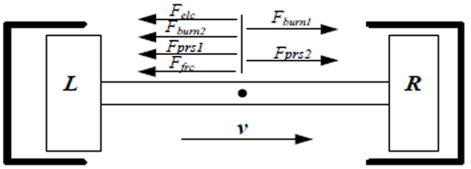
Schematic force diagram of the FPEG piston assembly.
According to Newton’s second law, the dynamic equation of the FPEG piston assembly is derived as follows:

Here, Fburn denotes the gas pressure force in the combustion chamber, Fprs represents the gas pressure force in the scavenging chamber (with subscripts 1 and 2 distinguishing the two cylinders on either side); Felc is the electromagnetic resistance force, and Ffrc is the frictional force of the moving assembly.
When the piston assembly moves from the TDC to the bottom dead center (BDC), the energy equation is expressed as follows:


Here, Eburn1 denotes the total energy released by combustion in combustion chamber 1 (assuming combustion chamber 1 releases heat through combustion, while combustion chamber 2 compresses the combustible gas mixture); Eburn2 is the energy consumed in compressing the combustible gas mixture in combustion chamber 2; Eprs represents the sum of energy consumed by compressing air in both scavenging chambers; Eelc corresponds to the energy absorbed by the generator; and Efrc accounts for the energy dissipated by all resistive forces.
To simplify the analysis, this study assumes that factors such as heat transfer and gas leakage in equation (2) do not cause energy losses. Due to abnormal heat release reducing Eburn1, the total sum on the right side of equation (3) consequently decreases. Given the fixed parameters of the generator and internal combustion engine, the increment of piston displacement x must inevitably diminish. When the piston displacement x fails to reach the ignition position, the generator will misfire and stall, as illustrated in Figure 2. The corresponding energy relationship is expressed by the following equation:


E refer represents the reference energy required to balance both sides of the equation, serving as a preset value. Once determined, it can be derived through the combination of the four parameters on the left side of equation (4). Equation (6) describes the desired state, but in actual operation, scenarios corresponding to equations (5)–(7) may all occur. When the differences described by equations (5) and (7) are significant, phenomena such as piston collision or misfire-induced engine shutdown may be triggered. Combustion fluctuations are inherently unavoidable. When combustion fluctuations occur, Erefer can be positively adjusted based on the fluctuation characteristics to ensure equation (6) holds true, thereby constraining the variations in in-cylinder compression ratio caused by the fluctuations.
Compression ratio control
As established above, the four parameters on the left side of equation (4) can be obtained by integrating Fburn2, Fprs, Felc, and Ffrc along the displacement direction. Here, Fburn2, Fprs, and Ffrc can be determined based on the structural characteristics of the FPEG (Free-Piston Engine Generator) and are fixed once the system is assembled. Felc, however, represents the electromagnetic force generated by the current flowing through the coil under the influence of the induced electromotive force. The magnitude of the induced current is governed by the total impedance of the circuit. Since the internal resistance of the generator is fixed, the current—and consequently Felc—can be adjusted by regulating the external load impedance.
As shown in equation (3), when combustion fluctuations occur, Felc varies in the same direction as Eburn1, thereby maintaining the equilibrium expressed in equation (6). Therefore, by dynamically adjusting the equivalent load in real time, Felc can be controlled to follow combustion fluctuations. The incremental electromagnetic force compensates for the energy variations caused by combustion fluctuations, ensuring stable cylinder compression ratios. Felc can then be calculated as follows:

In the equation, Ki, K, Rr, RL, and L represent the generator’s thrust coefficient, back electromotive force coefficient, internal resistance, load impedance, and coil inductance, respectively.
From equation (8), it can be observed that a variation in the load impedance RL will induce a change in Felc, which is the desired outcome. The following assumptions are made here:

In the formula, KP is the regulation coefficient, which is a function of the load impedance. KP applies negative feedback regulation to the difference between the current compression ratio and the target compression ratio. This ensures that the relationship between the generator mover’s operating speed and the electromagnetic force, as characterized by Kadj, evolves in the direction that reduces the compression ratio deviation. Additionally, a PI controller is employed to rapidly achieve the target control, since sampling and control are not continuous in practice, this process is subjected to discretization, and the control process is expressed by equations (10)–(14):

Here, T denotes the sampling period, and i denotes the sampling sequence.

Here, e cr (i) denotes the discrete deviation sequence, and CR(i) denotes the discrete compression ratio sampling sequence.

Here, u(i) denotes the control input, u(0) denotes the initial control input, Kcp denotes the proportional gain of the PI controller, and Ti denotes the integral time constant.
When substituting equation (11) into equation (12), we can obtain:

Here, Kci = Kcp (T/Ti), which is the integral gain of the PI controller.
Equivalent load circuit and simulation verification
Equivalent load circuit
From the analysis above, it can be concluded that adjusting the total impedance of the generator-load circuit enables the regulation of the electromagnetic force Felc. Based on this principle, an equivalent load circuit is constructed, as shown in Figure 4.
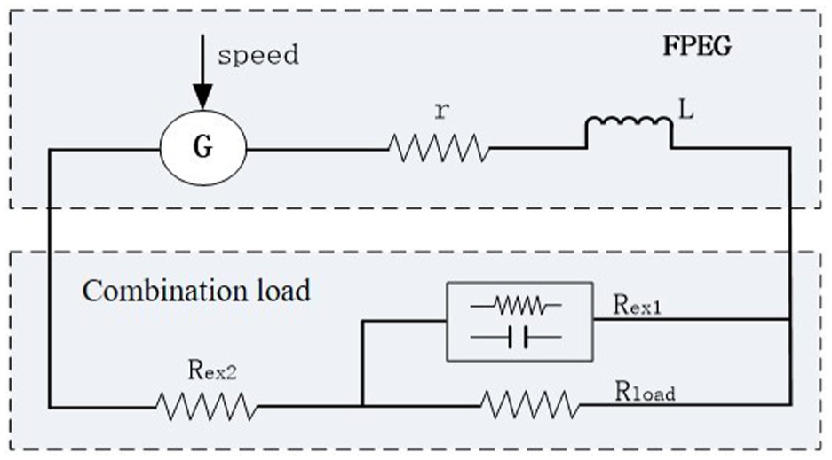
Equivalent circuit for generator load control.
From Figure 4, the generator equivalent model consists of three components: G, r, and L, where G represents the generator itself, r is the internal resistance of the generator coil, and L is the inductance of the generator coil. The load equivalent model comprises three parts: Rex2, Rex1, and RLoad. Here, Rex2 is the controllable series unit of the equivalent load, capable of adjusting the total load impedance upward. RLoad represents the main load (actual load), simplified as a purely resistive load for calculation purposes. Rex1 is the controllable parallel unit of the equivalent load, composed of resistive elements and a supercapacitor, enabling downward adjustment of the total impedance.
In this branch, the supercapacitor stores the diverted electrical charge. Under the control strategy, the circuit formed by RLoad and Rex1 subsequently consumes this stored energy. Since Rex1 is an equivalent impedance and does not physically dissipate energy, the electrical energy is ultimately absorbed by RLoad. For simplicity, assuming the supercapacitor is sufficiently large, its capacitive reactance becomes negligible, allowing Rex1 to be approximated as a purely resistive component.
Both Rex2 and Rex1 are equivalent load units. Their impedance characteristics can be achieved by controlling the voltage-current relationship, without physically consuming energy (in reality, there exists a milliohm-level resistance with negligible energy dissipation). Under ideal conditions, all electrical energy generated by the generator is absorbed by RLoad.
After adding the equivalent load, the relationship between the work done by the electromagnetic force of the FPEG and the work done by the current can be expressed by equation (14).

In the formula, Rex2 and Rex1 work in coordination. When the load power needs to be reduced, this can be achieved by upward adjustment of the impedance, where Rex1 is open-circuited, and the current flows through the series circuit composed of RLoad and Rex2. In this scenario, adjusting Rex1 allows an increase in the total load impedance, and equation (14) can be simplified as:

When the load power needs to be increased, this can be achieved through a downward adjustment of the impedance. In this scenario, Rex2 is short-circuited, and the current flows through the parallel circuit composed of RLoad and Rex1. By adjusting Rex2, the total load impedance can be reduced, and equation (14) can be simplified as:

Model construction
As illustrated in Figure 5, Figure 5(a) depicts the overall model of the FPEG system. The model comprises four core modules: Felc is an electromagnetic resistance module, responsible for outputting electromagnetic resistance; Ff is a friction force module, generating equivalent frictional resistance; Fengine is the generator module of the FPEG, delivering driving force externally; Joint is the computational module that calculates piston position and velocity parameters under the combined forces. Notably, the implementations of the Ff, Fengine, and Joint modules are based on existing research 18 and are not further explored in this study.

Simulink model: (a) overall FPEG system model and (b) electromagnetic resistance model of the generator.
Figure 5(b) depicts the electromagnetic resistance model of the generator. Position Module serves as a piston position correction module, employing a symmetric measurement method referenced to the midpoint of the piston stroke. This ensures that both opposed pistons use their respective cylinder TDCs as positional benchmarks. The real-time compression ratio is obtained by first subtracting the output value X_ec from the effective stroke X_eff, and then performing a division operation. The Triggered module determines the piston’s TDC position and outputs the corresponding compression ratio value at this position. This value is then subtracted from the predefined compression ratio CR_standad to generate an error signal. The error signal is processed by a PI controller to derive an adjustment coefficient. To ensure the adjustment coefficient remains within the system’s permissible range, a filter module is incorporated for safety range control. Final Output: The regulated adjustment coefficient, combined with the rated load coefficient Kmag and piston speed Spd, undergoes integrated computation to yield the controllable electromagnetic force Felc.
Model validation
Experiments are important means for researching the VLC method. Here, the experimental method is used to verify the effectiveness of VLC. The experimental measurement scheme is shown in Figure 6, and the basic information of the measurement equipment is presented in Table 1. A power analyzer is used to measure power; a charge amplifier is used to measure cylinder pressure and rail pressure signals; the controller (Electronic Control Unit, ECU) is used to measure the piston position signal, which serves for compression ratio control. The variable load control signal is the control signal that the ECU sends to the equivalent load, and this signal regulates the magnitude of the equivalent load’s impedance.

Experimental measurement scheme.
Basic information of measurement equipment.
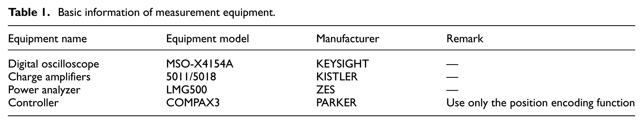
The basic parameters of the experimental system are as follows: the effective piston stroke is 0.02 m, the maximum stroke is 0.04 m, piston mass is 2.5 kg, the cylinder diameter is 0.034 m, the rated load coefficient is 3.7 N/(m s−1), the corresponding load impedance value is 200 Ω, and the target compression ratio is 4.
The comparison between experimental and simulation results is shown in Figure 7. It can be seen from the figure that the experimental data and simulation data of the compression ratio are relatively close, with the error controlled within 5%. This thus indicates that the model can accurately predict the variable load control of the FPEG, providing theoretical support for the research on the operation control of the FPEG.
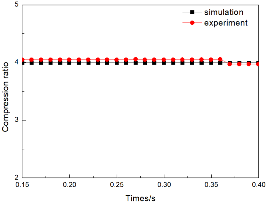
Compression ratio variation curves of simulation and experiment data.
Analysis of FPEG characteristics under variable load control
The application of variable load control will have a significant impact on piston motion, therefore the operational characteristics of the FPEG will also change under such control. Based on the above control model, this study investigates the effects of variable load control on FPEG performance by varying piston mass, heat release, ignition position, and valve overlap length.
Effect of piston mass on FPEG operational performance
The piston masses were selected as 2, 3, 4, 5, and 6 kg as variable masses, and the cylinder pressure characteristics, piston acceleration, output power, piston motion frequency, and indication efficiency of the generator are simulated separately. The simulation conditions are detailed in the Table 2 below.
Basic simulation conditions (variable mass).

As shown in Figure 8, the cylinder pressure reaches a stable state near 0.2 s, and it can be seen that the peak cylinder pressure increases with the increase of mass, and the cycle period also increases accordingly. The causes of this phenomenon can be explained as follows. Under conditions of stable heat release and controlled compression ratio, increased mass will result in reduced acceleration of the piston after passing TDC, while combustion continues within a progressively constrained space. At the same time, this space is formed by the movement of the piston. The larger the mass of the piston, the slower the acceleration, resulting in a smaller space corresponding to the completion of complete combustion. At the same time, the heat release remains constant, leading to an increase in cylinder pressure.

Curve of cylinder pressure variation with mass.
The relationship between piston acceleration and mass is shown in Figure 9, and the reasons for acceleration changes have been explained in the analysis of Figure 8. From this figure, the impact of piston mass on the performance of the generator can be observed from an operational perspective.
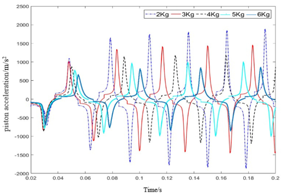
Curve of acceleration variation with mass.
As shown in Figure 10, with the increase in piston mass, the reciprocating frequency and the output power decrease by approximately 34.9% and 38.3%, respectively, both showing a relatively large decrease. Meanwhile, the indicated efficiency also decreases by 1.9%, suggesting a slight decrease. On the contrary, the load coefficient increases by almost 56.7%, which indicates a significant increase. The reasons are as follows. As analyzed above, the reciprocating cycle of the piston increases with its mass, which directly leads to a decrease in frequency. Furthermore, since the heat released during combustion remains constant, a lower operational frequency results in reduced output power. Under a controlled compression ratio, the energy consumed during compression remains constant. When the piston mass increases, maintaining this constant energy can only be achieved by reducing the piston speed during the compression process. Since the released energy must be converted into electrical energy for external output, increasing the load factor allows higher electrical energy generation even at lower piston speeds, thereby maintaining a constant external energy output. Although the work done to the outside remains basically unchanged during each combustion process, the output power observed from the outside shows a decreasing trend due to the reduction in work frequency. However, this has no significant impact on the indicated efficiency, so the indicated efficiency curve, as shown in the figure, is relatively smooth.

Variation curves of FPEG parameters with mass: (a) variation curves of frequency and load factor and (b) variation curves of output power and indicated efficiency.
Effect of ignition position on FPEG operating performance
Using the top of the cylinder as the reference zero-point, ignition positions at 4, 5, 6, 7, and 8 mm were selected to investigate the impact of ignition position on the operational performance of the FPEG. The simulation conditions are detailed in the following Table 3.
Basic simulation conditions (variable ignition position).

As evident from Figure 11, all four curves achieve complete stabilization around 0.16 s. Near this temporal position, the in-cylinder gas pressure state allows for distinct observation. As the ignition position moves closer to the cylinder top, the cylinder pressure decreases correspondingly, thereby extending the combustion cycle duration. The underlying reasons are as follows: Under normal conditions, the in-cylinder combustion process initiates at the ignition point and continues until a specific moment after TDC. Assuming a fixed combustion duration, advancing the ignition position prolongs the post-TDC combustion phase. During this extended period, the piston has already begun its downward stroke. Complete fuel combustion occurs at a position further from the cylinder top as the ignition point moves closer to the piston crown. This will further lead to a decrease in cylinder pressure during complete combustion. When the piston mass is constant, the cylinder pressure will decrease and the piston acceleration will also decrease, as shown in Figure 12. Therefore, when the acceleration is reduced, the piston’s operating speed decreases and leads to an extended cycle period. As a result, the closer the ignition position is to the top of the cylinder, the longer the cycle period will be.

Curve of cylinder pressure variation with ignition positions.

Curve of acceleration variation with ignition positions.
From the above analysis, as the ignition position moves away from the top of the cylinder, the piston speed will increase and the frequency will also increase, the frequency increases by approximately 19.3%, as shown in Figure 13(a). When the heat release per combustion cycle is constant, the work done will increase as the frequency increases, and the output power increases by near 5.6%. However, since the cylinder pressure increases as the ignition position moves away from the top of the cylinder, this results in more compression energy being consumed, which in turn leads to a rapid decrease in indicated efficiency—the indicated efficiency decreases by approximately 10.6%, as shown in Figure 13(b). Furthermore, since the increased work output causes by the ignition position being distant from the cylinder top and the energy consumption from compression work offset each other, the actual external power output exhibits minimal variations as shown in Figure 13(b). Consequently, the piston can only acquire sufficient kinetic energy to reach the desired TDC when it captures a relatively high proportion of combustion-released energy during a single combustion cycle. This process can be controlled by reducing the load factor, thereby maintaining stable system compression ratio. The variable-load control automatically regulates this adjustment mechanism, as illustrated in Figure 13(a).

Variation curves of FPEG parameters with ignition positions: (a) variation curves of frequency and load factor and (b) variation curves of output power and indicated efficiency.
Effect of heat release on FPEG operating performance
During generator operation, factors such as atomization efficiency, scavenging loss, and fuel supply irregularities may result in actual fuel combustion being lower than anticipated values. Therefore, this study investigates the impact of different heat release levels on generator performance, selecting 16.8, 23.6, 30.3, and 37 J as specific heat release values for analysis. The simulation conditions are detailed in the Table 4 below.
Basic simulation conditions (variable heat release).

Figure 14 shows the relationship curve between heat release and cylinder pressure. Within the same cycle, the greater the amount of heat released during a single combustion event, the higher the cylinder pressure becomes. Additionally, the piston cycle period decreases as the heat release increases. The rationale is as follows. When controlling the compression ratio, the greater the heat input into the combustion chamber per cycle, the higher the pressure generated within the confined space. This elevated pressure creates increased force on the piston crown, thereby driving the piston to accelerate more rapidly, as demonstrated by the acceleration profile shown in Figure 15. Furthermore, under controlled compression ratio conditions where piston stroke length remains fixed, increased piston acceleration leads to higher mean velocity, consequently reducing the cycle period. The correlation between cycle duration and heat release magnitude can be observed in both Figures 14 and 15, as demonstrated by their respective parameter variation patterns.

Curve of cylinder pressure variation with heat release.

Curve of acceleration variation with heat release.
Figure 16 shows the curves of other parameters of FPEG with changes in heat release. As can be seen from Figure 14, the piston frequency increases with the increase of heat release, increasing by approximately 25.2%, as shown in Figure 16(a). Meanwhile, when both the heat release per cycle and the piston frequency increase, it will inevitably lead to an increase in output power, with an increase of approximately 217%, as shown in Figure 16(b). To preserve compression ratio stability, the energy required for piston gas compression necessitates incremental adjustment proportional to heat release variations, achieving dynamic compensation for TDC displacement caused by rapid pressure transients. However, due to the insufficient energy required for balance to offset the single increase in heat release, only when the external output energy increases can the piston motion remain stable. The load coefficient is automatically adjusted upwards under variable load control, which can increase the absorption power of the load and better meet the energy requirements of the piston to move to the expected TDC. The adjustment process of load factor is shown in Figure 16(a). Because of the increase in heat release per cycle in the cylinder, the compression stroke requires more work to be consumed. Furthermore, higher cylinder pressure enables the piston to gain greater speed when moving away from the TDC; this in turn affects the combustion process after the TDC, resulting in a decrease in indicated efficiency of approximately 7.7%, as shown in Figure 16(b).

Variation curves of FPEG parameters with heat release: (a) variation curves of frequency and load factor and (b) variation curves of output power and indicated efficiency.
Effect of valve overlap length on FPEG operating performance
When the piston is not controlled, the length of valve overlap has a significant impact on the movement of the piston. 18 After adopting the variable load control method to stabilize the compression ratio, its characteristics undergo significant changes. Here, five valve overlap lengths of −2, −1, 0, 1, and 2 mm were selected to study their impact on the operational performance of the generator. Among them, the negative sign indicates that the compression stroke of the two cylinders does not overlap, and the number represents the free stroke displacement of the piston when both exhaust ports are open; The positive sign indicates that the compression stroke of both cylinders overlaps, and the number represents the overlap length. The simulation conditions are shown in the following Table 5.
Basic simulation conditions (variable valve overlap length).

As shown in Figure 17, around 0.1 s, all five curves with different overlapping lengths reached equilibrium. As the overlap length increases, there is a slight increase in peak cylinder pressure, while the piston cycle period becomes shorter. The reasons are as follows. When the overlap length varies, the ignition position and single-cycle heat release remain stable. With the implementation of variable load control, the compression ratio is also maintained constant. Consequently, the in-cylinder combustion process corresponding to different overlap lengths remains relatively stable. Additionally, during variable load control, the stabilization of the compression ratio alters the piston’s motion state, thereby resulting in the observed variation in peak cylinder pressure as illustrated in Figure 17. Simultaneously, under this pressure, minor variations in acceleration are induced, as illustrated in Figure 18. This process is automatically accomplished under variable load control. As the valve overlap length increases, the total piston stroke shortens, while the changes in acceleration remain relatively small. This results in a reduced deviation in piston cycle speed, ultimately leading to a shorter piston cycle period, as demonstrated in Figures 17 and 18.

Curve of cylinder pressure variation with valve overlap length.

Curve of acceleration variation with valve overlap length.
As shown in Figure 19, with the increase of valve overlap length, the piston operating frequency and output power both steadily increase. According to the analysis in Figure 17, as the valve overlap length increases, the piston operating cycle decreases, thereby leading to a corresponding rise in the operating frequency, which increases by approximately 10.2%, as shown in Figure 19(a). The reduction of the stroke during simultaneous operation leads to a shortened working distance of the piston, and the energy released by combustion needs to be completely released at the reduced distance. At the same time, the energy required during the compression stroke is constant, so it is necessary to increase the external energy output to maintain a stable compression ratio. Using a higher load factor can increase the absorption power of the load. Under variable load control, the load factor will automatically increase to balance the kinetic energy of the piston, thereby maintaining a stable compression ratio. Figure 19(a) shows the variation of the load coefficient with valve overlap length, with an increase of approximately 18.7%. With the increase in piston operation frequency and load coefficient, the system’s external output power will increase by approximately 13.7%, as shown in Figure 19(b). During the process of stabilizing the compression ratio under variable load control, the variation in valve overlap duration has a negligible impact on the compression and combustion processes. Therefore, its impact on the indicated efficiency is extremely slight, with an increase of approximately 0.08%, as illustrated in Figure 19(b).

Variation curves of FPEG parameters with valve overlap length: (a) variation curves of frequency and load factor and (b) variation curves of output power and indicated efficiency.
Conclusion
The FPEG lacks the mechanical constraints inherent in crank connecting rod mechanisms, rendering it susceptible to piston motion variations caused by combustion fluctuations and other unforeseen factors. These variations propagate to subsequent cycles, altering the compression ratio and degrading combustion conditions. Implementing variable load closed-loop control enables automatic adjustment of the load coefficient, facilitating energy redistribution between external output and piston motion maintenance. This ensures the piston sustains optimal compression energy, stabilizing the generator’s compression ratio, and it is also suitable for multi-fuel applications. Based on the variable load control theory, a simulation model with the stable compression ratio as the control target is established and verified. Furthermore, starting from improving the performance of FPEG, the optimal performance parameters in the control process can be optimized. As piston mass increases, parameters exhibit a consistent monotonic trend without extreme values. When ignition position shifts backward (away from the cylinder’s top), output power remains stable with minimal increase, contrasting with the substantial power decrease observed in FPEGs without variable load control. With varying heat release, indicated efficiency slightly decreases while other parameters rise. Conversely, changes in valve overlap length result in stable indicated efficiency but minor fluctuations in other parameters. In conventional FPEGs, as the valve overlap length increases, all parameters increase significantly. Therefore, through the research on the performance of generators under variable load control, this study provides a theoretical basis for the development of future control systems and the optimized design of generator prototypes.
Footnotes
Handling Editor: Fabian Andres Lara Molina
Funding
The authors received no financial support for the research, authorship, and/or publication of this article.
Declaration of conflicting interests
The authors declared no potential conflicts of interest with respect to the research, authorship, and/or publication of this article.