
Abstract
This paper presents a low-cost, vision-based model for detecting and segmenting wear zones on cutting inserts. The system integrates a Vividia 2.0 MP handheld USB microscope with a MATLAB-based algorithm to enable automatic image segmentation. A total of 250 images were collected during machining on a CNC lathe (TCN 410-1250, SINUMERIK 840D), under controlled laboratory conditions, covering various wear states. The model includes pre-processing, morphological segmentation, visualization, and dimensional analysis. Results show high segmentation performance, with an accuracy of 0.99 ± 0.001 and precision of 0.92 ± 0.017. The proposed approach eliminates the need for expensive imaging setups by relying on a low-cost microscope and a simple computational pipeline. While the current setup was tested under controlled laboratory conditions, results indicate strong potential for reliable in situ monitoring of tool wear. The system is designed to be easy to implement and scalable, and this pilot study provides a solid foundation for future validation in real-world manufacturing environments. By supporting early detection of tool degradation, the approach could contribute to predictive maintenance strategies aimed at improving productivity, reducing downtime, and enhancing product quality.
Keywords
Introduction
Modern manufacturing systems are evolving rapidly under the influence of automation, artificial intelligence, and cyber-physical systems.1,2 These technologies are transforming traditional production processes by enhancing flexibility, efficiency, and product quality. At the same time, increasing global competition is pressuring national industries to adopt smarter and more adaptive approaches.3–5 In response, the implementation of smart factories—where physical and digital environments are tightly connected through embedded sensors, processors, and actuators—has become essential. These cyber-physical systems enable real-time data exchange, process optimization, and autonomous decision-making, forming the backbone of intelligent and reliable manufacturing environments.6,7 In such highly automated environments, maintaining the reliability of physical components—particularly cutting tools—becomes increasingly important.
Despite the rapid advancement of manufacturing technologies, subtractive material removal processes continue to play a central role in industrial production. Even with the rise of additive manufacturing, machining remains essential for achieving high surface quality and dimensional accuracy. In this context, the condition of the cutting tool—particularly the state of its cutting edges—has a direct impact on surface finish, machine downtime, and overall production costs.8–11 As a result, real-time monitoring of tool wear, accurate prediction of tool life, and timely replacement strategies are crucial, especially in high-volume manufacturing environments. 8 To address these challenges, researchers have developed a variety of tool condition monitoring approaches, which are typically classified into two categories: indirect and direct monitoring methods. 5
Within this general classification, recent literature further organizes tool wear monitoring strategies into three broad groups: sensor-based approaches, data-oriented predictive models, and direct vision-based inspection techniques.12–14 Sensor-based approaches infer tool degradation by measuring physical quantities such as cutting forces, vibration, acoustic emission, or temperature. Data-oriented models, typically implemented through machine learning or deep learning, utilize large volumes of historical or real-time data to estimate tool wear. While these models can achieve high predictive accuracy, their adoption in small and medium-sized enterprises is often limited by the need for extensive labeled datasets and substantial computational resources. Recent studies rarely address solutions that balance predictive accuracy with low implementation costs and minimal computational requirements, leaving a gap for lightweight, easily deployable systems.12,14,15
Indirect methods rely on the acquisition and analysis of signals from various sensors, such as dynamometers (cutting forces), acoustic emission sensors, vibration sensors, thermocouples (temperature), microphones (sound), and motor current sensors.7,8,16,17 These approaches can be implemented without direct visual access to the tool, but their accuracy may be influenced by cutting conditions, material properties, and sensor placement.
Direct methods, on the other hand, capture and analyze images of the cutting tool to explicitly assess wear patterns, offering the added advantage of visual confirmation. Vision-based systems have gained considerable attention for their ability to provide both qualitative and quantitative insights into tool wear and have been successfully applied across diverse domains, often in combination with machine learning and artificial intelligence.12,18 As a type of direct monitoring method, these approaches are known for their high accuracy and potential for real-time implementation.19–24 The level of automation—whether in-line, on-line, or off-line—can significantly influence their effectiveness in industrial settings.5,11,17 Depending on the monitoring objective, different image segmentation and classification methods are used to extract relevant wear features. Common techniques include thresholding methods (e.g. Otsu), contour-based approaches (e.g. active contour models), morphological operations, and machine learning algorithms such as neural networks, support vector machines, and convolutional neural networks (CNNs).17,19,25
Recent developments also explore hybrid approaches, combining sensor-based signals with vision-based inspection to enhance robustness and compensate for individual method limitations. 15 Nevertheless, in uncontrolled industrial environments, variations in lighting, surface reflectivity, and camera positioning can compromise segmentation accuracy, which calls for image processing pipelines that remain reliable on the shop floor.12,14,26 Although advanced techniques—such as convolutional neural networks, vision transformers, infrared thermography, and hybrid sensor setups-show strong performance, their deployment often depends on controlled lighting, specialized or costly hardware, and high computational resources, while manual segmentation persists in some workflows, introducing subjectivity and inconsistency, which limits adoption in everyday industrial environments, particularly in small and medium-sized enterprises.19,23,25,27
In this context, there is a growing interest in developing lightweight, robust, and cost-effective monitoring systems that can be easily implemented without major modifications to the production line. Systems that rely on standard USB microscope cameras and well-established image processing techniques, such as morphological operations, present a promising direction. These methods enable reliable wear assessment with minimal setup, low cost, and real-time operation—making them suitable for real-world machining environments where adaptability and simplicity are key. 12
Building on the general context of tool condition monitoring, understanding the fundamental mechanisms of tool wear is essential for designing effective monitoring strategies and forms the basis for the approach presented in this study. Tool wear is primarily caused by tribological interactions between the cutting tool and the workpiece. When two surfaces move in contact, friction, heat, and mechanical stress lead to gradual material degradation.
In metal cutting, these effects are especially pronounced at the tool–chip and tool–workpiece interfaces, where stress gradients and high temperatures result in forms of wear such as flank wear, notch wear, comb cracks, plastic deformation, and crater wear.28,29 These wear modes are governed by complex tribological processes involving adhesion, abrasion, diffusion, and oxidation, whose relative dominance depends on cutting parameters, tool material, and workpiece composition.
This understanding provides the physical foundation for selecting appropriate monitoring indicators and designing robust detection algorithms. Wear mechanisms directly influence cutting forces, temperature distribution, chip formation, surface quality, machining precision, and tool life.12,30 Such impacts make early wear detection critical for efficient production and maintenance planning. The present study focuses on the automated monitoring and identification of these specific wear forms, which are illustrated in Figure 1.

Common types of wear on cutting inserts.
In response to the need for more practical and cost-effective tool wear monitoring solutions, this paper presents a vision-based model for the automatic segmentation and quantification of wear zones on cutting inserts. As a preliminary step, this study explores the feasibility of implementing vision-based wear detection in a stable laboratory environment, laying the groundwork for future validation in industrial settings. By combining a low-cost handheld digital microscope with morphological operations implemented in MATLAB, the proposed method demonstrates accurate detection of tool wear under controlled laboratory conditions. While conventional approaches often rely on expensive imaging systems and controlled lighting environments, this solution aims to provide a more affordable and accessible alternative. Although not yet validated in real shop floor conditions, the results from this pilot study indicate strong potential for integration into future manufacturing workflows. Improved wear monitoring could contribute to better product quality, reduced machine downtime, and more efficient operations.
Embracing the integration of advanced technologies is essential in order to enhance productivity and maintain competitiveness in the evolving industrial landscape.3,8
Materials and methods
Experimental set up
The experimental procedure was conducted at the Laboratory for Metal Machining and Tribology, Faculty of Engineering, University of Kragujevac, using a TCN 410-1250 CNC lathe equipped with a SINUMERIK 840D control unit (www.echo-eng.it). A Vividia 2.0 MP handheld USB digital microscope (http://www.vividia-tech.com, Woodruff, SC, USA) was mounted on the side of the lathe to record images of the cutting insert during machining, under controlled laboratory conditions. This high-resolution device provides a resolution of 1600 × 1200 pixels and up to 300× magnification, and was connected to a PC for real-time image capture and offline analysis (Figure 2).

Position of the camera relative to the cutting tool.
The microscope was placed in a dedicated magnetic holder mounted on the lathe’s carriage, ensuring a stable, vibration-resistant, and repeatable imaging setup. The cutting insert was periodically brought into the microscope’s fixed field of view after a defined number of machining passes. Image capture was manually triggered via a button located on the microscope cable, eliminating the need for any mechanical movement of the camera itself. This simple and robust arrangement preserved the low-cost and easily deployable nature of the proposed system, while maintaining consistent image quality throughout the experiment.
The experimental setup also included a model for the segmentation and dimensional analysis of wear zones on the cutting inserts, implemented on the PC (Figure 3). The test workpiece was made of gray cast iron EN-GJL-200 (composition: C 3.39%, Si 2.11%, Mn 0.48%, P 0.10%, S 0.087%, Se 0.95%) with dimensions Ø50 × 350 mm. 18 Machining was performed at a cutting speed of 265 m/min, feed rate of 0.3 mm/rev, depth of cut of 4 mm, and spindle speed of 1000 rev/min.

Schematic of experimental setup with tool, camera, and workpiece.
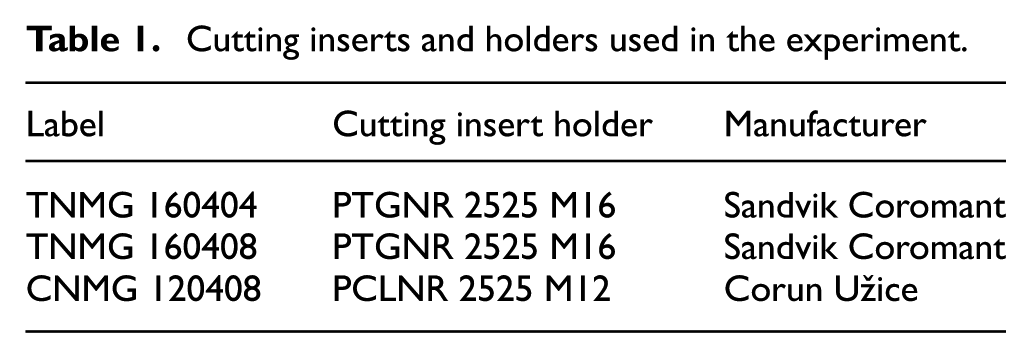
Table 1 presents the types of cutting inserts and tool holders used in the experiment.
Cutting inserts and holders used in the experiment.
A total of 250 images of cutting inserts were acquired during machining under varying wear conditions. These images were later used to create two databases for evaluation: one manually segmented by an expert (serving as ground truth) and the other segmented using the proposed model.
To ensure accurate dimensional analysis of wear zones, image calibration was performed prior to testing. A calibration image was captured immediately after mounting the camera in its final position, using a standard millimeter ruler placed in the same focal plane as the cutting insert and recorded under identical lighting conditions (Figure 4). From this image, a pixel-to-millimeter ratio (1 mm ≈ 48 px) was determined and applied throughout the segmentation algorithm to convert wear dimensions into real-world metric values. The validity of this conversion was confirmed through a preliminary comparison with contact meter measurements, revealing a maximum deviation of ±0.05 mm. While this level of precision is not at the micrometer scale, it is sufficient for reliable wear measurement in laboratory settings and shows potential for future industrial validation.
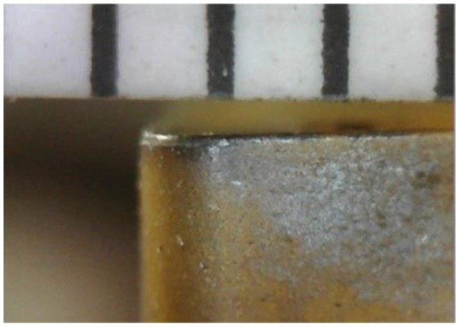
Calibration image captured with a physical reference scale (millimeter ruler) for determining the pixel-to-millimeter ratio used in dimensional analysis.
All machining was performed under dry cutting conditions, without the use of coolant. The cutting tool was periodically brought into the camera’s field of view after a defined number of machining passes—typically every 5–10 passes—depending on the insert type and wear progression. Image acquisition was performed manually by the operator using only the integrated LED lighting of the microscope.
Data acquisition and image segmentation
The images obtained from the experimental procedure were used as input data for the tool wear segmentation and dimensional analysis model developed in the MATLAB environment (https://uk.mathworks.com). Image processing and analysis were conducted at the Center for Integrated Product and Process Development and Intelligent Systems (CIRPIS), Faculty of Engineering, University of Kragujevac.
The image processing pipeline (Figure 5) included four main stages: pre-processing, morphological segmentation, visualization, and wear parameter measurement. To ensure algorithm robustness, performance was evaluated throughout the development process.
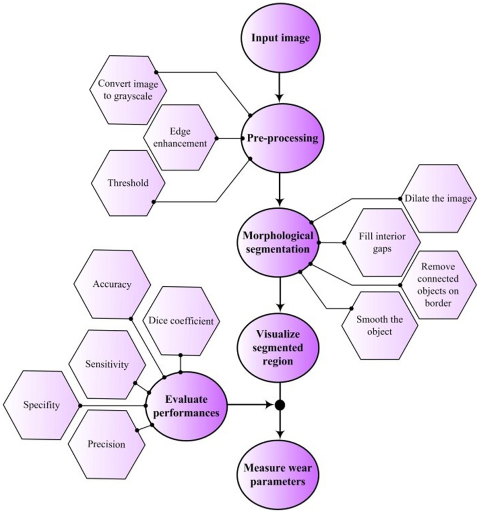
Flowchart of the algorithm for segmentation, visualization, and performance evaluation of cutting insert wear.
Although images were acquired under consistent experimental conditions, variations in lighting, insert color, and wear types required pre-processing to enhance relevant features. These steps included grayscale conversion, edge enhancement, thresholding, and noise reduction.31,32
As illustrated in Figure 6, pre-processing aimed to improve clarity and contrast, thereby increasing the effectiveness of subsequent segmentation steps. The Sobel operator—a discrete gradient-based filter—was applied with a kernel size of 3 × 3 to enhance edge definition by calculating intensity gradients in the horizontal and vertical directions. These gradients represent local changes in pixel intensity and are used to detect edges, which typically correspond to transitions between worn and unworn regions of the cutting inser.22,33

Improving quality and clarity using the Sobel filter.
The Sobel operator uses two convolution kernels to approximate the first derivative of the image intensity function:


where Mx and My represent approximations of the image intensity gradients in the horizontal and vertical directions, respectively.
These operators are applied via convolution across the grayscale image, and the magnitude of the gradient at each pixel is calculated as:

This gradient magnitude highlights regions with strong intensity transitions, which often correspond to wear boundaries. Intensity gradients are not constant—they vary across the image and are highest at edges, providing critical spatial information for edge-based segmentation.
Following pre-processing, morphological operations were applied to refine object boundaries (Figure 7). These operations manipulate binary image elements using a structuring element. The mathematical formulations of these operations are based on the definitions provided by Hazzan and Pacella. 33
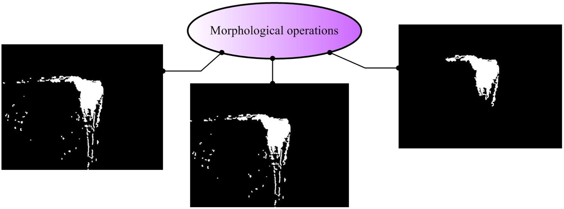
Application of morphological operations for segmentation.
Dilation expands objects to fill gaps:

while erosion removes boundary pixels to smooth and isolate objects:

Combined, these operations produce the final segmented matrix:

where A is the binary image, B the structuring element, and S the segmented result.
The structuring element B was selected through systematic preliminary testing on a representative subset of the dataset. Several shapes (disk, square, and diamond) and radii ranging from 1 to 5 pixels were evaluated based on segmentation accuracy, noise suppression, and contour preservation. A disk-shaped element with a radius of 3 pixels consistently provided the best balance between effective removal of small noise artifacts and retention of wear-edge geometry under the given imaging conditions. This choice ensured stable segmentation performance across different wear types, lighting variations, and insert materials observed in the experiment.
A manually defined intensity threshold was used for binarization, typically around grayscale level 100, based on visual inspection of representative samples.
The segmented output was used to calculate wear parameters and visualize worn regions. The system included an interactive measurement tool to quantify distances of interest directly on the segmented region (Figure 8), enabling high-precision evaluation of cutting-edge degradation.
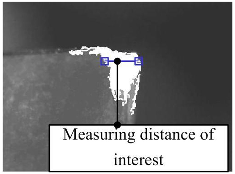
Measuring region of interest on the segmented image.
Measurements were calibrated based on a pixel-to-millimeter ratio derived from a reference image, and distances were calculated using Euclidean metrics within the MATLAB environment.
This method supports detailed segmentation and visualization of worn zones, offering a practical approach for automated assessment of tool wear in machining processes. The selected parameter values proved effective across the dataset, ensuring consistent and reliable performance under the defined imaging conditions.
The reliability of the segmentation output was later validated through comparison with manually segmented ground truth images, as discussed in Section “Performance evaluation.”
Performance evaluation
The reliability of the proposed segmentation model was assessed using standard performance metrics derived from the confusion matrix: sensitivity, specificity, accuracy, and precision. 31 Two image datasets were used for evaluation. The first dataset contained 250 cutting insert images manually segmented by an expert, serving as the ground truth. The second dataset comprised the same images processed using the proposed model.
The predicted segmentation was compared to the ground truth on a pixel-by-pixel basis, and average values with standard deviations were reported for each performance metric. The following formulas were use:


where:
TP (True Positive): Pixels correctly classified as wear in both the ground truth and model output,
TN (True Negative): Pixels correctly classified as non-wear in both images,
FP (False Positive): Pixels incorrectly classified as wear by the model but not in the ground truth, and
FN (False Negative): Pixels classified as wear in the ground truth but missed by the model.
To further quantify the similarity between the model output and the ground truth, the Dice similarity coefficient (DSC) was calculated 34 :

The Dice coefficient ranges from 0 to 1, with higher values indicating greater overlap and higher segmentation accuracy.
Results
The proposed segmentation model was applied to various images of cutting inserts collected during the experiment. Table 2 shows representative examples of original images, expert-segmented ground truth, and model-segmented images, along with corresponding wear measurements. These illustrate the model’s capability to detect a range of wear geometries with high precision. The wear measurements include the maximum length (L) and depth (D) of the segmented wear zone.
Representative segmentation results with corresponding wear measurements.

The model successfully identified and measured small-scale wear features, with wear lengths ranging from 0.35 to 1.52 mm and depths from 0.10 to 0.92 mm. These results indicate the model’s capability to detect fine wear details and accurately estimate geometrical dimension.
The average values of the confusion matrix metrics were as follows: Sensitivity = 0.85 ± 0.055, Specificity = 0.99 ± 0.000, Accuracy = 0.99 ± 0.001, Precision = 0.92 ± 0.017, and Dice coefficient = 0.89 ± 0.098.
Figure 9 presents a box-and-whisker plot representing the statistical distribution of L/D ratios across 250 samples, encompassing both typical and extreme cases of wear geometry. The median L/D value is approximately 3.1, while several outliers above 10 correspond to shallow but extended wear zones. These outliers were intentionally retained to highlight the robustness of the segmentation algorithm and its ability to maintain stable measurement output even under atypical and pronounced tool wear.

Box plot of the L/D ratio distribution for 250 cases.
These values demonstrate high segmentation accuracy and consistency, with strong overlap between the predicted and ground truth wear zones. Visual inspections further confirmed that the model effectively distinguished worn and non-worn regions, even in cases of subtle or irregular tool damage. No major over- or under-segmentation was observed. These findings confirm the robustness of the proposed model under controlled laboratory conditions and highlight its potential for future application in real-world tool condition monitoring.
Discussion
Modern manufacturing requires reliable monitoring solutions compatible with real production constraints. This study introduces a low-cost system for tool wear detection, validated under controlled laboratory conditions, and designed with future industrial deployment in mind.8–10,35
However, accurate and real-time monitoring of tool wear and breakage remains a persistent challenge in both research and industrial practice.7,16–19,25
Motivated by current challenges in tool wear monitoring—particularly the need for affordable, reliable, and easily deployable solutions—we developed a vision-based model intended as a foundation for future applications in real-world production environments. 23 The system was tailored to address practical shop-floor conditions, including lighting variability and inconsistent wear patterns, although initial testing was conducted in a controlled laboratory setting. These factors guided the development of a robust and modular segmentation algorithm with potential for seamless integration and real-time deployment.
The proposed system is designed to integrate easily into existing production workflows without requiring major modifications. By enabling timely detection of tool wear, it has the potential to support increased productivity and reduce the time and resources typically required for routine monitoring. As a result, this approach may contribute to lower production costs over time through extended tool life and reduced maintenance needs, pending further validation in real manufacturing environments.
Móricz et al. employed indirect methods for tool wear assessment based on post-process microscopic image analysis and geometric evaluation of tool condition, as well as direct methods involving vibration signal analysis. 36 In contrast, our approach enables visual identification of insert wear during machining, allowing timely data acquisition with minimal reliance on external hardware or post-processing procedures. This improves practicality for laboratory-based evaluations and lays the groundwork for future in situ implementations.
The proposed tool wear monitoring model offers several key advantages. It demonstrates the feasibility of in situ and real-time damage detection through automatic image segmentation based on morphological operations, reducing reliance on manual inspection and minimizing the risk of human error. Designed for adaptability within existing workflows, the system can support more timely tool replacement and improve operational efficiency. Moreover, its automation capabilities help mitigate operator dependence and reduce subjectivity common in semi-automated visual inspection systems.
In high-volume production, our approach has the potential to provide direct visual feedback during machining, thereby shortening response time in failure-critical applications.5,8,25 Consistent with the findings of Hassan et al., 14 who emphasize that timely detection of tool wear significantly reduces waste and unplanned downtime, our model demonstrates the feasibility of monitoring that can enable prompt recognition of critical wear during machining, which may help to reduce deterioration in quality and productivity.
Various vision-based approaches for tool wear monitoring have been explored in recent studies. Thakre et al. acquired insert images using a digital camera mounted on a fixed stand, while Yoshimitsu et al. employed two CCD cameras directly integrated into a machining center.37,38 Brili et al. used infrared thermography to assess the thermal condition of the cutting tool during operation. 23 Although effective, these methods often rely on costly equipment or require tightly controlled experimental setups.
The combination of a USB microscope and morphological segmentation enables automated detection of tool wear without the need for complex hardware configurations or post-processing steps, while achieving consistent segmentation performance in laboratory tests. Compared to the method proposed by Daicu and Oancea, 24 which involved manual identification of wear zones, our solution minimizes operator influence and supports broader deployment. Furthermore, it operates independently of thermal sensors or dedicated lighting systems, offering a streamlined and adaptable alternative. 23 The findings of Kasiviswanathan et al. 15 support the idea that simple, well-tuned visual approaches can match the accuracy of more sophisticated systems—even in industrial contexts—underscoring the broader applicability of our method, particularly for future validation in small and medium-sized enterprise environments.
Similar to the findings of Pimenov et al., who demonstrated the feasibility of direct vision-based tool wear monitoring under controlled illumination using a CCD camera, 12 our approach also relies on visual inspection but is designed with potential adaptability to variable shop-floor conditions in mind. While their system was limited by sensitivity to ambient light, our model showed robust segmentation results under modest natural variations in laboratory lighting. Beyond approaches relying solely on visual inspection, hybrid methods that combine multiple sensing modalities have also been explored to enhance detection robustness. In this context, the findings of Bagga et al. 13 confirm the advantages of hybrid strategies, but at the cost of higher equipment investment and more complex data processing. In contrast, our method operates using only low-cost optical hardware and achieves promising segmentation accuracy in a simplified setup, suggesting its potential as an accessible solution for small and medium-sized enterprises, pending further validation.
While changes in ambient lighting are a known challenge for vision-based monitoring, the proposed system maintained segmentation accuracy using only the microscope’s integrated LED light, without any supplemental lighting.37,39 This was achieved by fine-tuning threshold values during pre-processing to extract the region of interest. Final segmentation was performed using the Sobel edge detection operator, whose effectiveness in tool wear applications has been confirmed by Kerr et al. and Junior et al.22,40 These results demonstrate robustness under stable laboratory conditions and suggest potential adaptability to environments with limited lighting control.
Wear-induced damage often appears as irregular and deformable shapes, making morphological operations particularly effective for accurately segmenting worn regions. Prior studies have demonstrated the suitability of these operations for complex tool wear geometries. 41 In our approach, the segmented image allows straightforward of wear parameters, such as length, width, and perimeter without removing the insert from its mounted position on the machine. The measured wear depths closely match those reported by Thakre et al., who used pre-worn inserts under controlled conditions. 37 Our results were obtained using low-cost equipment under stable laboratory conditions, highlighting the accuracy and potential practical relevance of the method. Furthermore, the system enables users to interactively select and analyze specific geometric features of interest, supporting a more detailed understanding of wear progression. However, it is worth noting that reflectivity and local contrast on certain insert materials may influence segmentation accuracy. Future iterations of the algorithm could incorporate adaptive thresholding or multi-channel imaging to improve robustness under challenging conditions.
The visual outputs generated by the proposed method have the potential to support decision—making in production environments. Engineers and operators can use the segmented images and dimensional wear data to identify tools approaching critical wear limits and to plan replacements more effectively. This approach may contribute to the development of predictive maintenance strategies, help reduce unplanned downtime, and support more efficient production planning in future implementations.
The performance of the proposed model was evaluated using standard classification metrics derived from the confusion matrix, including sensitivity, specificity, precision, accuracy, and the Dice coefficient. 42 The consistently high values of these indicators confirm that the segmentation was accurate and that the method is reliable within the tested laboratory conditions. In particular, high sensitivity demonstrates the model’s ability to correctly detect tool wear, while high specificity reflects its robustness in avoiding false detections. Together, these metrics highlight the model’s effectiveness in controlled settings and its potential applicability in future industrial implementations.
The distribution of L/D values across the tested samples reflects the progressive nature of tool wear under repeated machining passes. As expected, inserts subjected to a higher number of cutting cycles exhibited increased flank wear, which is evident from elevated L/D ratios. While the majority of values fall within a stable range, the presence of outliers—corresponding to L/D ratios above 10—suggests localized instances of accelerated degradation, potentially due to brittle fracture, overheating, or inclusion-related effects. These findings demonstrate the ability of the segmentation algorithm in capturing a wide spectrum of wear intensities and reveal how wear progression manifests through both gradual trends and abrupt localized failures over successive machining cycles.
During implementation, we encountered challenges related to lighting variability and camera positioning, which affected image consistency. As part of future work, we plan to refine the data acquisition process to improve robustness across different operating environments. We also aim to extend the model to recognize more complex wear patterns and tool geometries. Additional testing across a wider range of tool types and surface finishes will be pursued to confirm the method’s adaptability across industries and applications.
Importantly, the proposed system is not limited to a single industry. It could be adapted to various sectors—including automotive, aerospace, and medical device manufacturing—where cutting tools with similar geometries are widely used. As such, the model demonstrates potential for practical and scalable tool condition monitoring, and may contribute to improved productivity, reduced operational costs, and enhanced product quality through timely decision-making based on visual insights.
The novelty of this work lies in the integration of cost-effective imaging hardware with a fully automated segmentation algorithm designed to maintain performance under non-ideal conditions. While many existing approaches still require controlled laboratory setups or high-cost sensors, this method aims to balance simplicity, accuracy, and practical applicability. By addressing several common barriers to implementation, the proposed system demonstrates potential as a promising alternative, particularly in pilot-stage implementations seeking low-cost, scalable solutions.
Conclusion
This study presents a vision-based model for in situ tool wear detection that combines a low-cost USB microscope with morphological image processing. The method demonstrates accurate segmentation under controlled laboratory conditions, without reliance on expensive equipment or specialized lighting. Experimental results showed high sensitivity and specificity, while maintaining affordability and implementation simplicity-indicating that this pilot implementation holds strong potential for future validation and broader us, especially in small and medium-sized enterprises.
Remaining challenges, such as sensitivity to lighting and camera alignment, will be addressed through improved acquisition protocols and extension to more complex wear patterns. The approach also shows promise for broader applications beyond turning operations, supporting the development of intelligent maintenance strategies and contributing to more efficient, cost-effective manufacturing systems in future implementations.
Footnotes
Handling Editor: Divyam Semwal
ORCID iDs
Author contributions
SPS, MP, and ADj conceptualized the study and defined the methodology. MI collected the experimental data. AM, AJ, and JB analyzed the results and participated in data processing. SPS and MP wrote the first draft of the manuscript. All authors contributed to the discussion of the results, revised the manuscript, and approved the final version.
Funding
The authors received no financial support for the research, authorship, and/or publication of this article.
Declaration of conflicting interests
The authors declared no potential conflicts of interest with respect to the research, authorship, and/or publication of this article.
Data availability statement
The datasets generated during and/or analyzed during the current study are available from the corresponding author on reasonable request.