
Abstract
This study addresses the issue of vertical-pitch dynamic coupling in active suspension systems caused by traditional velocity-feedback control. We introduce a novel ADF-PID control strategy that combines acceleration difference feedback (ADF) decoupling with PID control to independently regulate vehicle vertical and pitch angular accelerations. The approach generates an ADF signal by analyzing discrepancies between the accelerations at the front and rear suspension connection points and the vehicle’s center of mass, enabling effective decoupling of vertical-pitch motion. Additionally, a velocity-error-feedback PID system is utilized to simultaneously reduce both vertical and pitch angular accelerations. The simulation results show that the proposed technique effectively reduces vertical acceleration and significantly enhances pitch angular acceleration under various road conditions, including bump and random roads. On a bump road surface, the ADF-PID control system increases vertical acceleration by 5.5% and pitch angle acceleration by 89%, compared to reference. In three-bump road scenarios, vertical and pitch angle accelerations improve by 81% and 96%, respectively, compared to a passive suspension setup. Additionally, under excitation-class C road conditions, vertical acceleration rises by 19% while pitch angle acceleration increases by 93% relative to the passive suspension system.
Keywords
Introduction
The key role of the vehicle suspension system is to protect occupants from mechanical vibrations caused by road irregularities, which in turn enhances passenger comfort and safety. Moreover, this system plays an essential part in preserving vehicle stability while reducing the negative impact of road surfaces on the vehicle’s components.1–3 Based on their operational principles and features, vehicle suspension systems are typically classified into three categories: passive, semi-active, and active suspension systems. 4 The passive suspension system is widely implemented in the shock absorption mechanisms of many vehicles due to its uncomplicated structure and cost-effectiveness. However, these systems exhibit only static properties, which greatly constrain their ability to adapt to constantly changing road conditions or vehicle velocities. As a result, when sudden alterations in road profiles happen, the passive suspension system often struggles to deliver a suitable and prompt reaction.
To tackle the intrinsic performance constraints of conventional passive suspension systems, researchers have carried out persistent studies and achieved the successful creation of semi-active and active suspension systems. The scope of research in these systems includes both the incorporation and utilization of various control methodologies, as well as fostering the advancement and innovation of novel suspension systems by leveraging the combined effects of these strategies. This process contributes to broadening the scope of vehicle dynamics control research, as outlined in references.5–25 Previous studies on the advancement of semi-active and active suspension systems primarily centered on employing the velocity error signal of the sprung mass and the dynamic displacement of the suspension as key feedback inputs. On this basis, vehicle suspension systems were designed and refined using various control approaches. The findings from these investigations cover a wide range of applications, including optimal control techniques,9,13,16,23,26,27 fuzzy control and its associated methods,8,15,18 as well as preview model predictive control (PMPC).10,11 Furthermore, they delve into sliding mode control,17,28,29 learning-based advanced control strategies, 19 robust control theory implementations,20,24,28,29 and novel developments in active disturbance rejection control (ADRC).21,22 Collectively, these efforts strengthen the theoretical underpinnings of vehicle suspension control and provide a variety of practical technical options.
Previous investigations into vehicle suspension systems have shown that the expense of high-quality acceleration sensors restricts the use of spring-loaded mass acceleration signals as feedback in the development of active suspension control systems.13–25 In relevant studies, active suspension control systems utilizing acceleration feedback30,31 often apply advanced noise reduction techniques to process velocity data, creating alternative acceleration feedback for designing these systems. Nevertheless, the creation of such systems is frequently hindered by the processing capabilities of the vehicle’s embedded core system and hardware constraints like memory size, complicating real-world implementation. Moreover, the inherent time delay in generating acceleration signals significantly affects the stability and effectiveness of the control system.32,33
To expand the scope of research in vehicle suspension systems and improve scientific approaches, researchers have successfully created a new component called the inerter, which employs acceleration as a feedback mechanism. Following this, the mechanical architecture of the inerter was carefully engineered, and associated mechanical analysis frameworks were developed.34–39 The emergence of the inerter, combined with recent progress in acceleration sensor technology and reduced costs, allows for the integration of acceleration feedback into the design of vehicle suspension control systems, opening up a promising research field with considerable potential for growth and innovation. Additionally, when contrasted with earlier studies, 6 the vehicle suspension control system that incorporates acceleration feedback exhibits notable improvements in performance.
An alternative approach to designing the vehicle suspension control system is through the implementation of dynamic decoupling. As a vehicle moves across a rough road surface, the natural variation in wheelbase between the front and rear wheels tends to generate interconnected vibration effects. These effects involve both the vertical acceleration experienced by the vehicle and its body pitch angle. This type of dynamic response has a considerable influence on the overall performance of the vehicle, notably decreasing ride comfort while also presenting a significant challenge to handling stability. As such, managing and mitigating vertical and pitch angular accelerations have emerged as critical areas of focus within vehicle dynamics research. In this context, the decoupling control strategy for vehicles has attracted substantial interest due to its superior ability to suppress vibrations.21,28,29,40,41 The fundamental principle of these approaches is to dynamically regulate the distribution and compensation mechanism of the vehicle’s onboard mass, ensuring that the equivalent wheelbase remains consistent during operation. Consequently, the previously interconnected systems of vertical and pitch angular acceleration are successfully separated into two distinct two-degree-of-freedom dynamic models corresponding to the front and rear wheels. Building upon this foundation, further exploration into the design of active suspension control systems is carried out to enhance the precision of vehicle dynamic control.
Driven by the analysis presented earlier, this article is motivated by a detailed examination of the feedback signals that reflects the discrepancy between the vertical accelerations of the vehicle’s front and rear wheels and the centroid acceleration. Expanding on this foundation, the article introduces a dual-channel control algorithm, which merges the decoupled control of the vehicle’s vertical and pitch motions with a PID control methodology. The key contribution and novelty of this technique reside in its ability to leverage the acceleration difference signal for achieving separate regulation of the vehicle’s vertical and pitch dynamics, thus improving operational stability and maneuverability. Below is a summary of the main contributions of this work.
(1) This research introduces a decoupling control method for managing vehicle vertical and pitch movements using the ADF signal. The fundamental concept of this approach involves employing the acceleration values at the connection points between the front and rear suspensions and the vehicle body, along with the variation in centroid acceleration, as feedback inputs. By fine-tuning the feedback proportionality coefficient, supplementary control signals are provided to the actuator. The main objective is to ensure the resultant force of ADF control forces, which are acting on the front and rear suspensions, keeps to zero dynamically. This effect enables the separation of vertical and pitch motions in the vehicle.
(2) One significant benefit of this strategy is its capability to effectively control pitch motion without the need for extra sensors, utilizing only the currently available vehicle acceleration data. The simulation findings indicate that incorporating the acceleration difference feedback can substantially enhance pitch angular acceleration performance, and increasing the feedback proportionality coefficient leads to even better control outcomes.
(3) The dual-channel separation of the vehicle body’s vertical and pitch movements is achieved through the implementation of a PID control strategy. In the ADF decoupling control framework, the difference in vertical speed between the suspension and the vehicle body serves as the feedback signal for PID regulation. By fine-tuning the PID feedback parameters, the system effectively mitigates both vertical and pitch angular accelerations of the vehicle. Within the designed dual-channel control structure, theoretical analysis and simulation results demonstrate that when the front and rear feedback coefficients of the ADF control algorithm adhere to a particular proportional relationship, the vertical acceleration stabilizes. Meanwhile, as the feedback coefficient increases, the pitch angular acceleration progressively diminishes toward zero. Consequently, the decoupling control for the two motion patterns has been successfully accomplished.
This study is organized into the following sections. In section “Half-car model with active suspension,” the half-car model equipped with an active suspension system used in this article is described. Section “ADF decoupling with PID control strategy” presents the novel ADF-PID control strategy. Two theorems are introduced to explain the decoupling dynamics and the separation in controlling vertical and pitch angular accelerations. Furthermore, an analysis of the stability for the closed-loop control system is included. Section “Numerical simulations and discussions” involves performing numerical simulations to validate the proposed ADF-PID control strategy’s applicability and efficiency for the specified vehicle system. These findings are then compared and evaluated in relation to results from other sources. Lastly, the study concludes with final observations.
Half-car model with active suspension
A 4-degree-of-freedom half-car model, as shown in Figure 1, is employed to replicate a vehicle equipped with an active suspension system. Within this model, z
c
indicates the vertical displacement of the sprung mass m
c
,
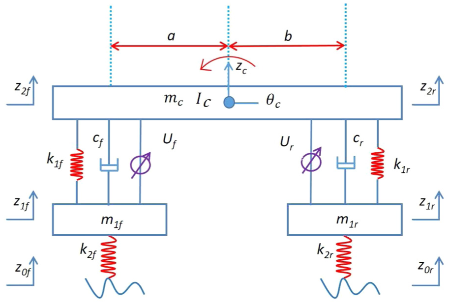
Schematics of half-car model.
List of physical parameters.

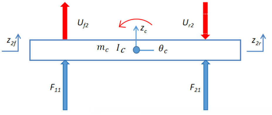
For the forces applied to the vehicle by the front and rear suspension systems, as depicted in Figure 2, the dynamic equations of the four-degree-of-freedom half-car model can be derived as follows.

Force diagram of half-car model.
The equation for the vertical motion of the vehicle body,

The equation for the body pitch angle,

Equation of motion for the unsprung mass of the front suspension,

Equation of motion for the unsprung mass of the rear suspension,

In this context, the variables can be described as, z 1f refers to the vertical movement of the front suspension system, z 1r corresponds to the vertical movement of the rear suspension system, z 0f indicates the vertical position change of the road surface associated with the front suspension, and z 0r represents the vertical position change of the road surface linked to the rear suspension. These displacement-related variables are satisfied by

The variables of velocity and acceleration can be sequentially derived by taking time derivatives.


The applying forces


The variable U f and U r indicate the overall actuating force produced by the actuator in the front and rear suspensions, respectively. F11 and F21 correspond to the passive forces of the front and rear suspension systems, respectively.
Due to the nonlinear behavior exhibited by the half-vehicle model, nonlinear damping and spring forces are mainly integrated into the passive elements of the front and rear suspension systems. The detailed formulation of the nonlinear half-car model can be found in Appendix A. The primary objective of this research is to develop an active suspension control system based on a linearized version of the half-vehicle model. In the following, F11 and F21 are represented by


ADF decoupling with PID control strategy
The objective of the active control algorithm design is to enhance the performance of the vehicle. In the context of a four-degree-of-freedom half-vehicle model, the vertical acceleration and pitch angular acceleration of the vehicle body serve as critical indicators of vehicle performance. Notably, the pitch angular acceleration arises due to the force imbalance between the front and rear suspensions. In this section, a novel ADF-PID control strategy is presented and the control algorithm architecture is illustrated in Figure 3. The proposed scheme comprises two distinct components of the control strategy.
(1) An active compensation control strategy for pitch motion is developed based on the ADF signal. This strategy utilizes the difference in acceleration between the connection points of the front and rear suspensions with the vehicle body and the centroid acceleration as a feedback signal. The difference is then multiplied by the vehicle body mass and a specific proportional coefficient to generate an additional control input for the actuator. The primary goal of this control strategy is to ensure the resultant force of the applying forces on the front and rear suspensions by the ADF maintains to zero dynamically.
(2) A separation control strategy for the vertical and pitch movements of the vehicle body is proposed. In this approach, the vertical velocity error of the suspension relative to the vehicle body is used as the feedback signal. A PID control strategy is employed to suppress both the vertical acceleration and adjust the pitch angular acceleration simultaneously.
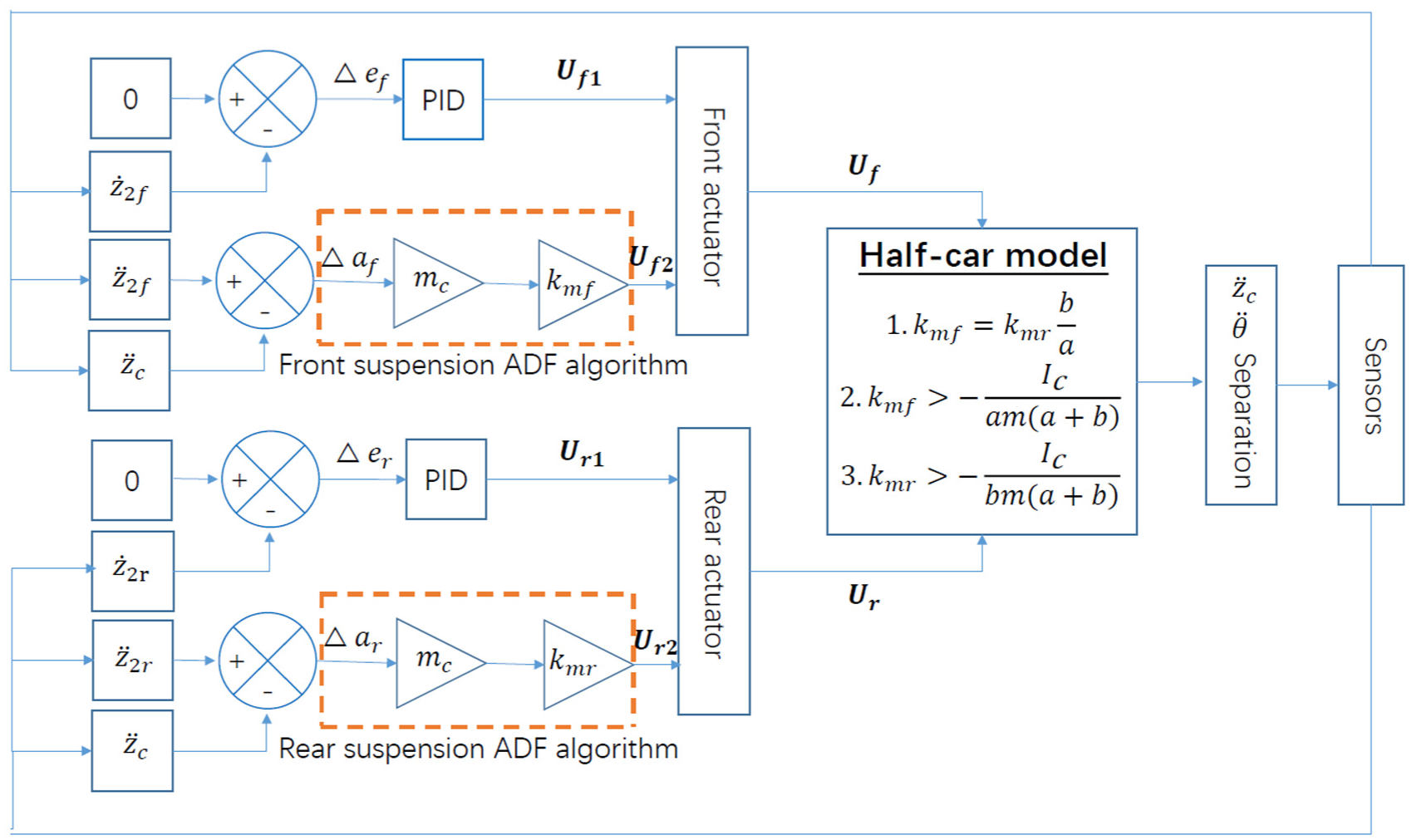
Architecture of ADF-PID decoupling control.
The total control forces of the actuators in the front and rear suspensions, denoted as U f and U r in equations (8) and (9), are each divided into two parts.


The
PID control strategies based on velocity error between the suspensions and the vehicle body.
The velocity errors at the interface between the front and rear suspension systems and the vehicle body,


For


In the formula, k pf , k if , and k df represent the proportional, integral, and differential coefficients of the PID algorithm for the front suspension, respectively. Similarly, k pr , k ir , and k dr denote the proportional, integral, and differential coefficients of the PID algorithm for the rear suspension.
(1) Decoupling control strategy based on ADF signals.
Considering the acceleration difference (AD) signals


The AD signals leverage solely the currently sensed vehicle acceleration data, eliminating the need for additional sensors. Furthermore, the ADF-based decoupling control strategies have been proposed for the forces of


Here, equations (6) and (7) are utilized, where k mf and k mr represent the feedback proportional coefficients in the ADF algorithm for the front and rear suspensions, respectively.
The subsequent section provides an in-depth analysis of the decoupled and independent control characteristics associated with the vertical and pitch motions of the half-care model, as influenced by the ADF-PID control strategy.
Near-vertical motion invariance

The acceleration of the vehicle body maintains consistency.
Force diagram of half-car model under the sole action
At this point, the equation of motion for the half-car model in the vertical direction is

Substituting equations (20) and (21) into equation (23) and simplifying the resulting expression, it obtains the result.

When the condition in equation (22) is satisfied, the resultant force of the ADF control force becomes zero, as indicated by

Force diagram of half-car model with
In Figure 5, z*
c
, z*
1f
, and z*
1r
denote the vertical displacements of the center of mass of the vehicle body, the front and the rear suspensions, respectively, under applying the zero resultant force of the ADF control force,


The equation for the vertical motion of the vehicle body is yielded

Through the process of deducting the equations obtained from equation (23) with

Due to the effect of the actuators in both the front and rear suspension systems, the alteration in the vertical movement of these suspensions is remarkably negligible, suggesting that

Therefore, equation (28) can be rewritten as

From equation (29), it is evident that the front and rear suspensions decoupling control strategies based on ADF, as outlined in equations (20) and (21), guarantee that when the feedback coefficients adhere to the proportional relationship described in equation (22), the control force derived from ADF has no effect on the vehicle body’s vertical movement. To put it differently, the vertical and pitch movements of the vehicle body are successfully separated and can therefore be managed separately.
Process of suppressing pitch movement
In the control system algorithms of the half-car model presented in the literature,8–25 the vehicle body’s pitch angular acceleration remains partially unsuppressed. Conversely, the ADF-PID control strategy introduced in this study successfully achieves both effective and comprehensive suppression of the vehicle body’s pitch angular acceleration.

Rewriting equation (30) by incorporating equation (22) facilitates obtaining the intended outcome.


Within this context,
(1) If the feedback coefficient for the ADF-based decoupling control force is adjusted to zero, this enables the velocity error feedback PID control algorithm to function independently. Under these conditions, the torque resulting from the passive driven force B stays unchanged. Here, the level of the action force C generated by the PID control algorithm has a direct impact on the pitch angular acceleration of the vehicle body. More precisely, when the direction of the force in term C corresponds with the direction of the passive driven force term B, there is an increase in the pitch angular acceleration of the vehicle body. On the other hand, if the directions are in opposition, the pitch angular acceleration of the vehicle body diminishes.
(2) If the feedback coefficients in the velocity error feedback PID control algorithm are all configured as zeros, the ADF-based decoupling control forces function without interference. With an increase in the A f , and A r feedback coefficients of the ADF control forces, the pitch angular acceleration of the vehicle gradually diminishes. When the A f , and A r coefficients tend toward an infinite value, the pitch angular acceleration is entirely constrained to reach 0.
(3) Upon implementing the ADF-PID decoupling control strategy, the velocity error feedback PID control algorithm becomes essential. Should the vehicle body’s pitch angular acceleration demonstrate a tendency to worsen, the ADF-based decoupling control forces offer significant support. With the rise in feedback coefficients Af, Ar, the worsening trend of the vehicle body’s pitch angular acceleration is gradually mitigated until it nearly reaches zero.
It is summary that, by employing the ADF-PID control strategy, the vertical motion and pitch motion of the vehicle body can be effectively separated and controlled. Consequently, the pitch angular acceleration of the vehicle body is significantly reduced to zero.
Analysis of stability
By incorporating equations (3)–(7) into equation (30), the expression can be streamlined to derive the outcome
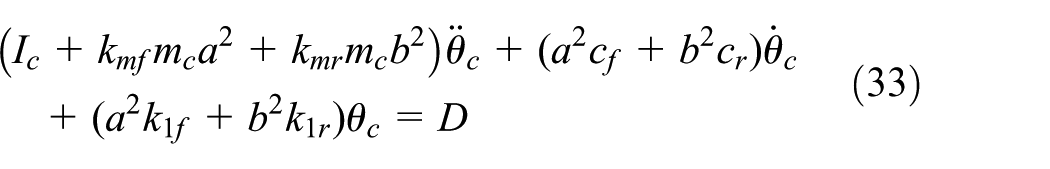
where

Numerical simulations and discussions
This part describes the simulation program and its implementation, which aim to verify the effectiveness of the proposed closed-loop control system. The development and execution of the program are carried out using the MATLAB-SIMULINK software environment. For numerical integration, the software’s integrated Runge-Kutta ode45 solver is utilized. A variable step-size approach is adopted, with a pre-specified tolerance value
The half-car model presented in equations (1) through (11) utilizes an ADF-PID control strategy, which is detailed in equations (16), (17), (20), and (21). In this study, the tuning of PID control parameters mainly relies on the speed error measured at the interface between the suspension and the vehicle chassis. The parameter adjustment process follows these stages.
Initially, the proportional component is calibrated. During this phase, the proportional gain is incrementally adjusted, and the real-time behavior of the speed error is closely observed. When the error diminishes and stabilizes near zero, it suggests that the selected proportional gain aligns well with the system dynamics, achieving the intended control outcome. With the proportional parameters set, the integral and derivative components are then optimized.
Next, the integral component is fine-tuned to eliminate any residual steady-state error. The integral gain is progressively raised, and the system is monitored over a prolonged period to assess whether the error continues to diminish. Finally, the derivative component is adjusted to minimize overshoot and dampen oscillations. By carefully tuning the derivative gain, the system can swiftly return to equilibrium when subjected to external disturbances, such as those induced by road surface variations.
Following multiple iterations of tuning and evaluation, the suspension system displayed superior dynamic response and stability across a range of operational scenarios, marking the successful completion of the PID parameter optimization process.
During the simulation process, the velocity error feedback PID control algorithm parameters are configured as
Verification of decoupling between vertical and pitch accelerations
The ADF-PID control strategy was applied in a closed-loop control system. Figures 6 –8 illustrate the outcomes of the vehicle body’s vertical acceleration and pitch angular acceleration associated with the three
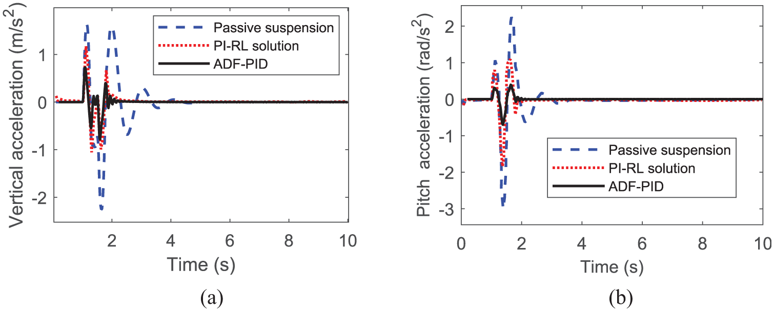
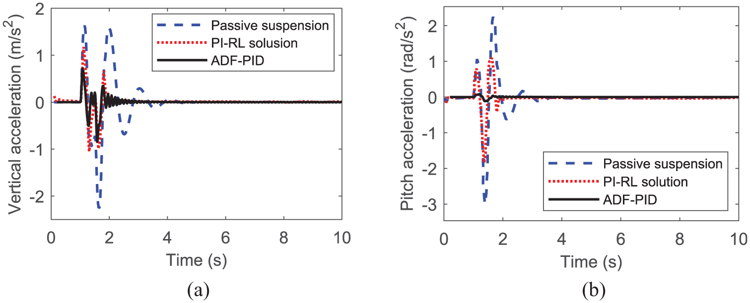
Time responses of vehicle accelerations for

Time responses of vehicle accelerations for
Time responses of vehicle accelerations for
Upon evaluating the outcomes of the three control approaches, passive suspension, PI-RL method, and ADF-PID control, it becomes evident that the ADF-PID control exhibits a modest enhancement in reducing the vertical acceleration of the vehicle body. Furthermore, its capability to mitigate the pitch angular acceleration of the vehicle body is notably substantial. As shown in Table 2, which displays the root-mean-squared (RMS) values for both vertical and pitch angular accelerations of the vehicle body, it is clear that with PID-ADF control (
RMS values of vehicle accelerations.

Furthermore, to confirm the decoupling performance of the vertical and pitch angular accelerations of the vehicle body, Figure 9 illustrates the RMS values associated with three distinct PID-ADF control setups, referred to as

Decoupling effect of vertical and pitch angular accelerations.
Spectrum analysis of performance for controlled system
Through the implementation of the ADF-PID control approach in active suspension systems, the design parameters are applied by

Spectrum of vehicle accelerations. (a) Vertical acceleration. (b) Pitch angular acceleration.
In Figure 10, for both the ADF-PID active control suspension system and the passive suspension system, the maximum amplitudes of the vehicle body’s vertical and pitch angular accelerations, along with their corresponding frequency values, are presented in Table 3. In the frequency band from 0 to 20 Hz, the ADF-PID active suspension control system exhibits markedly reduced amplitudes for both vertical and pitch angular acceleration vibrations compared to the passive suspension system.
Maximum amplitudes and relevant frequencies of vehicle accelerations.

With respect to the vertical vibration of the vehicle body, the passive suspension system displays a resonance peak at 5 Hz. In contrast, the active suspension system moves this peak to 11.5 Hz, along with a notable 77.2% decrease in vibration amplitude. This indicates that active control strategies successfully bypass the low-frequency resonance zone, particularly within the 1–8 Hz range to which the human body is most sensitive, while also limiting vibration energy transmission through adaptive damping.
Regarding the analysis of pitch angle acceleration, the active suspension makes a minor adjustment to the resonant frequency, shifting it from 6.75 to 7 Hz, which leads to an 83.4% decline in amplitude. This highlights the improvement in vehicle body stability achieved through active control, especially during dynamic maneuvers such as turning and braking, where it significantly minimizes the influence of pitch vibrations on vehicle handling. Additionally, in accordance with the ISO 2631-1 standard concerning human exposure to whole-body vibration, the active suspension system exhibits enhanced vibration performance over the entire 0–20 Hz frequency range. It achieves a reduction of over 60% in the RMS acceleration value compared to the passive system, thereby satisfying Class A comfort criteria. Collectively, these findings affirm that the ADF-PID control method efficiently reduces both vertical and pitch angular accelerations of the vehicle body.
Simulating tests on three-bump road and random road excitation
The ADF-PID active control suspension system is evaluated through two simulation scenarios involving excitation from a road surface featuring three consecutive bumps and a random excitation-class C road profile. The three-bump road comprises three sequential protrusions, each measuring 5 m in both width and length, with a height of 0.1 m. The layout of this multi-bump road structure is presented in Figure 11(a). For Simulation Case 1, the half-vehicle model operates at

Profiles of three-bump road and random road excitation. (a) Three-bumps road. (b) Random excitation-class C road.
The random excitation-class C road profile is chosen. 42 The differential equation in time domain is formulated as


where
Case 1. Results of the three-bump road surface
Figure 12 illustrates the vertical and pitch angular acceleration response characteristics of the vehicle body when subjected to excitation from a three-bump road profile. Detailed performance data are compiled in Table 4. In the context of the half-vehicle model with
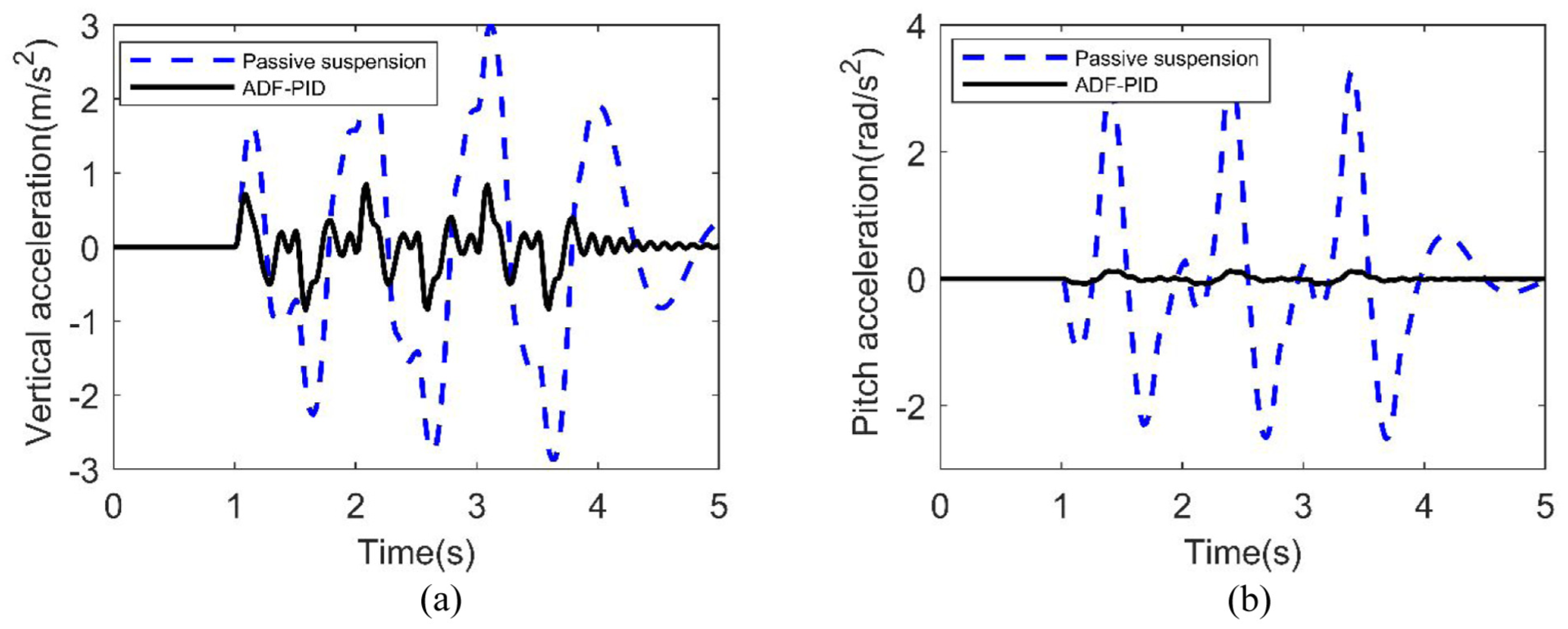
Time responses of vehicle accelerations for three bump road. (a) Vertical acceleration. (b) Pitch angular acceleration.
Performances for the three-bump and the excitation-class C roads.

Case 2. Results of the excitation-class C road profile
Figure 13 illustrates the vertical and pitch angular acceleration response curves of the vehicle body under excitation caused by the excitation-class C profile. The key performances are summarized in Table 4.

Time responses of vehicle accelerations for class C road. (a) Vertical acceleration. (b) Pitch angular acceleration.
In the Case 2, when operating at a speed of
In the context of pitch motion regulation, the ADF-PID control approach achieves remarkable results. That is, the RMS value of pitch angular acceleration
Conclusions
For the half-car model with four degrees of freedom, this work presents a sophisticated active suspension control approach. This method integrates acceleration difference feedback (ADF) and velocity error feedback PID control, named the ADF-PID control strategy, to achieve effective separation and regulation of the vehicle body’s vertical and pitch angular accelerations. More specifically, by utilizing feedback from the acceleration differences between the front and rear suspension connection points relative to the center of mass, the proposed technique effectively addresses the vehicle’s pitch motion and ensures decoupling of its vertical and pitch angular acceleration characteristics. Importantly, when the feedback coefficients for the front and rear suspensions under ADF control adhere to a defined proportional relationship, the vertical acceleration is stabilized. Additionally, as the ADF feedback coefficient increases incrementally, the pitch angular acceleration converges toward zero asymptotically.
Moreover, in the context of the ADF decoupling control framework, the velocity error feedback PID control facilitates separate regulation of the vehicle’s vertical movement and pitch angle, which improves the adaptability and flexibility of the control approach. An evaluation of the simulation results indicates that, when contrasted with alternative control methods in previous studies, the suggested method demonstrates enhanced effectiveness in mitigating vehicle acceleration under equivalent random road disturbances. Consequently, this research contributes valuable theoretical and numerical simulations for the development of active suspension systems.
However, the method proposed in this study is based on a PID control scheme, whose limitations primarily include insufficient system robustness, limited disturbance rejection capability, and high dependence on an accurate system model. To address these shortcomings, Afifa et al. 43 presents a systematic design approach that demonstrates improved performance. In future work, we will integrate the methodology from Afifa et al. 43 to enhance the applicability and effectiveness of the ADF-PID control strategy.
Footnotes
Appendix A
The nonlinear half-car model is obtained by the half-car model, as shown in equations (1)–(9), associated with the nonlinear passive forces of the front and the rear suspension systems. The nonlinear forces provided by the springs,
where
For the small variations of speed and displacement in suspension system, the nonlinearity is degraded to the linear case. By taking account of the nonlinearity provided in equations (A1)–(A4), the nonlinear passive forces of the front and the rear suspension systems are represented by
Therefore, the nonlinear half-car model is obtained by the equations (1)–(9), associated with equations (A5) and (A6).
Handling Editor: Pak Kin Wong
Funding
The authors disclosed receipt of the following financial support for the research, authorship, and/or publication of this article: This work was supported in part by Projects for Department of Science and Technology of Fujian Province (Grant nos. 2022HZ026025 and 2023T5001), Operational Funding of the Advanced Talents for Scientific Research (Grant no. 19YG04) of Sanming University, the Natural Science Foundation of Sanming University (Project Leader: Prof. Hai-Lian Hong, Grant no. KD23003P), the Program for Innovative Research Team in Science and Technology in Fujian Province University, and Fujian Provincial Engineering Research Center for Modern Mechanical Design and Manufacturing Technology. The authors also acknowledge the support from the School of Mechanical and Electric Engineering, Sanming University.
Declaration of conflicting interests
The authors declared no potential conflicts of interest with respect to the research, authorship, and/or publication of this article.