
Abstract
Rail transport is widely acknowledged as one of the safest modes of land transportation. However, derailments remain a significant safety concern that can lead to catastrophic outcomes. This paper presents results from a research aimed at supporting the design of effective derailment containment measures through numerical simulation techniques, employing a multibody model to simulate the post-derailment behaviour of a railway trainset. This model is combined with a finite element model of a track-based derailment containment device and is used to predict the forces on this structure resulting from the impact with the derailed train. The key innovations presented in this paper include the modelling of the entire trainset instead of a single vehicle, considering the effect of inter-vehicle interaction forces due to the traction gear and buffers, and the modelling of guard rails as an alternative to derailment containment walls which were previously investigated. The introduction of these new features enhances the scope and accuracy of the model, particularly providing a more accurate prediction of the impact forces which considers the effect of the interaction between adjacent vehicles, and the possibility to compare different derailment mitigation measures.
Introduction
Despite significant investments in railway safety, derailments continue to occur, caused by various factors such as component failure in rolling stock, poor track conditions, or extreme environmental conditions.1–4 These events could have catastrophic consequences both for people and goods. Thus, it is crucial not only to focus on reducing the likelihood of derailment events through prevention but also to minimize their consequences through effective containment countermeasures known as substitute guidance mechanisms (SGMs). These devices, which can be categorized into vehicle component-based, track-mounted or vehicle-mounted types, are designed to keep derailed trains as close as possible to the track centreline and mitigate the consequences of derailments. 5 This paper focusses on railway track-mounted SGMs, specifically derailment containment walls (DCWs) and guard rails (GRs), which can be installed in high-risk zones of the railway line.
The most reliable method for studying post-derailment dynamics and assessing the effectiveness of various containment devices is likely experimental testing. However, such tests are highly costly and challenging to conduct due to safety issues. Moreover, tests are typically performed at relatively low speeds, making them less representative of worst-case scenarios, especially for high-speed vehicles. In the literature, only a limited number of full-scale tests, both for derailment containment walls DCW6–8 and GRs, 9 are documented.
Thus, due to the impracticality of reproducing a full-scale derailment in controlled experiments, numerical simulations, both adopting commercial10,11 and self-developed codes,12,13 are used to predict post-derailment dynamics, estimate the impact forces exchanged with the SGM and evaluate the interaction of derailed vehicles with the railway infrastructure. However, even an accurate numerical simulation of post-derailment scenarios is highly challenging for several reasons: it requires modelling the large motion of the vehicles, accounting for a range of highly nonlinear contact-impact interactions, for example, between the derailed wheel and the ballast and sleepers, and capturing the significant deformations of the containment structure. 5
Previous works proposed by Brabie and Andersson10,11 primarily analyzed the effectiveness of vehicle-mounted containment devices. Similarly, studies in Japan 14 investigated the application of L-shaped guides on axle boxes to prevent deviations from the rails, while Wu et al. 15 explored the potential of using rolling stock components, such as brake disks, motors, and gearboxes, as guiding elements to limit vehicle displacement after derailment. These works mainly focussed on optimizing running gear design to reduce the consequences of derailment.
Beyond vehicle-mounted solutions, research has also addressed infrastructure-based containment devices: guard rails 13 and derailment containment walls (DCWs)8,16 have been studied to assess their effectiveness in limiting post-derailment vehicle movement. However, most of these studies rely on computationally expensive finite element models, typically consider a simplified single-vehicle model or adopt only one SGMs model.
Thus, with respect to other existing approaches for the simulation of post-derailment dynamics of railway vehicles, the model presented in this study (i) simulates the dynamics of the entire trainset rather than an isolated vehicle, explicitly accounting for detailed coupling systems models; (ii) includes multiple types of infrastructure-based containment devices, namely DCWs and guard rails; and (iii) offers high computational efficiency, with CPU times significantly lower than those reported in comparable finite element models, thereby enabling faster simulation of different derailment scenarios and the evaluation of alternative SGMs. These characteristics make the proposed model suitable for a systematic assessment of different SGMs across a variety of derailment scenario, providing practical insights for infrastructure managers.
In this context, this paper employs a multibody model for the simulation of post-derailment behaviour of railway vehicles running on a high speed curve, considering the contact-impact nonlinear model and the large motion of the vehicle body, presented in Santelia et al.17,18 In addition, the devices proposed to mitigate the consequences of the derailment are introduced by means of a finite element (FE) model, to account for their deformability. Finally, the overall model enables the computation of impact forces on the SGM, allowing for the estimation of the loads required for its proper sizing.
In this paper a further development of the model is proposed in two-fold direction. First, the model is extended to consider the whole trainset instead of a single vehicle, including the effect of the interactions forces between the vehicles due to the coupling systems. This extension of the model allows to consider the effect of inter-car forces exchanged by the derailing vehicle with the neighbouring vehicles in the trainset, which has a significant effect on post- derailment dynamics and, eventually, on the loads applied to the SGM. This is because the buffers on the inner side of the curve generate a compressive force whose line of action is offset for the car body centreline in a way that creates a yaw moment that acts to realign the derailed vehicle to the track. In this way, the speed at which the derailed vehicle approaches the SGM and hence the impact force are reduced. This effect is particularly relevant for the DCW as, compared to the GR, its position is more distant from the track centreline so the effect of the realigning moment is greater.
The second development of the model consists of the introduction of a FE-based model of the GRs, enabling the comparison of this SGM type with the alternative of a DCW.
The present design practice of track-mounted SGMs is largely based on simplifying assumptions regarding the loads acting on the SGM when impacted by the derailed train. Thus, this paper contributes to advancing the analysis of derailment containment provisions by providing an objective means to determine the loads produced by the impact, thereby supporting the structural sizing of the containment device. Furthermore, the paper provides a comparative evaluation between DCWs and GRs as alternative measures to mitigate the derailment event.
The paper is organized as follows: the multibody model of the single vehicle is first presented; then models to take into account the coupling system, composed by a traction gear and a pair of buffers, along with a new finite element model to consider a GR as containment device, are introduced. Then, different post-derailment scenarios are investigated and, finally, conclusions are drawn based on the simulations results.
Modelling
In this section the multibody model of the railway vehicle used for post-derailment simulations is introduced. In particular, the vehicle is modelled adopting a multibody approach coupled with finite element model (FEM) of the containment structures. The model also includes a specific contact module considering the interaction of the derailed wheels with the sleepers and ballast. With respect to the approach presented in Santelia et al., 17 the model is here extended to consider the dynamics of the entire trainset, introducing a mathematical representation of the forces exchanged between adjacent vehicles through the coupling devices (traction gear and buffers). Additionally, in this paper, a new type of derailment containment provision, that is, a GR installed inside the track gauge, is considered in addition to the derailment containment wall DCW analyzed in previous work.
Vehicle model
The model adopted in this paper considers a complete ETR500 high-speed trainset composed of the head locomotive, 11 hauled passenger cars and the tail locomotive. This train type is taken as a reference in this study because the ETR500 locomotive is the heaviest vehicle running on the Italian HS network at the present maximum service speed of the line, which is 300 km/h. As shown in Figure 1, the model of each single vehicle is composed by seven rigid bodies: one car body, two bogies, and four wheelsets. The rigid bodies are assigned with six degrees of freedom (DOF) each, for a total of 42 DOFs per vehicle and a grand total of 546 DOFs for the complete trainset.

Multibody model of the single railway vehicle composed by a carbody, two bogies and four wheelsets connected together by means of primary and secondary suspensions (side and top view). Red: body-fixed references and blue: global reference.
The primary and secondary suspensions of each vehicle are represented as massless (lumped parameter) viscoelastic compact elements17,19 with nonlinear characteristics defined in the form of force-deformation or force-velocity curves. Since large relative displacements are expected to take place between the bodies in the post-derailment phase, the model also considers bumpstop elements that are used to represent the possible contact between the bodies caused by their large displacements, for example, the contact of one wheel with the traction gearbox. The clearances of these bumpstops were defined based on the geometry of the bodies derived from technical drawings of the vehicles. More details on the single vehicle model can be found in Santelia et al. 17
From a mathematical point of view, adopting a standard multibody approach, 20 the equations of motion describing the single vehicle system dynamics are expressed as follows:

Where

Where
Vectors
Model of the coupling system
In this section models to account for the coupling systems between rail vehicles that allow to compose a complete trainset are introduced. Although numerous coupling systems exist, in the considered trainset the adopted one is based on buffers and screw couplers. 21 The aim of the screw couplers, and in general of the traction gears, is to secure the wagons together and transmit the draft forces, while the buffers prevent the vehicles from colliding with each other.
In this paper, the traction gear is represented by a nonlinear elastic and viscous damping element positioned between two consecutive vehicles, whereas a more complex model is adopted for the buffers, to reproduce the magnitude and the variable direction of the repulsive forces produced by these devices. Detailed descriptions of the mathematical models used for each component of the coupling system are provided in the following sub-sections.
The main reason to consider coupling systems in the analysis presented in this paper relies on the fact that these forces may represent one of the main factors that influence the safety of wagons during derailment.22,23 In fact, during curve negotiation the buffers compress and the screw couplers elongate to generate intercar forces that can affect the wagons stability and the running safety of locomotives.24,25 In case of derailment and post-derailments conditions, these coupling devices can also have beneficial effects as outlined in the results of this paper.
Model of the traction gear
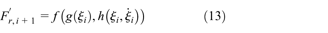
The traction gear system considered in this work is a screw coupler made by two hooks and a chain, and is modelled according to Cheli et al. 26 This model characterizes the gear as a nonlinear viscoelastic component, 19 as shown in Figure 2, which takes into account the initial pre-tension applied through a screw. The force produced by this element is expressed as:

where

where

Model of the screw coupler between two consecutive vehicles.
Finally, once the force
Model of the buffers
The buffers are also modelled as nonlinear viscoelastic elements, but, in this case, they are only able to transmit compressive forces. The model of the buffers used in this work is based on Cheli and Melzi. 27 The compressive force exchanged by each buffer is expressed as:
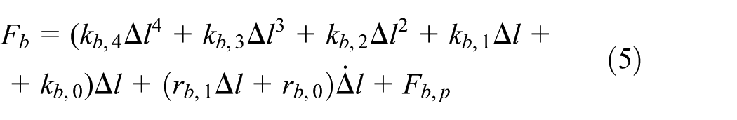
Where
To completely model the dynamic behaviour of the side buffers, two additional independent coordinates must be introduced in the multibody model, one for each couple. In particular, for each railway vehicle two additional state variables (
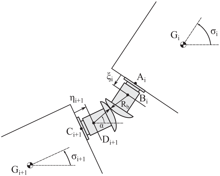
Kinematics of the contact between two adjacent buffers.
When the buffer’s compression becomes null, the buffers are no longer in contact and the axial force and the displacement
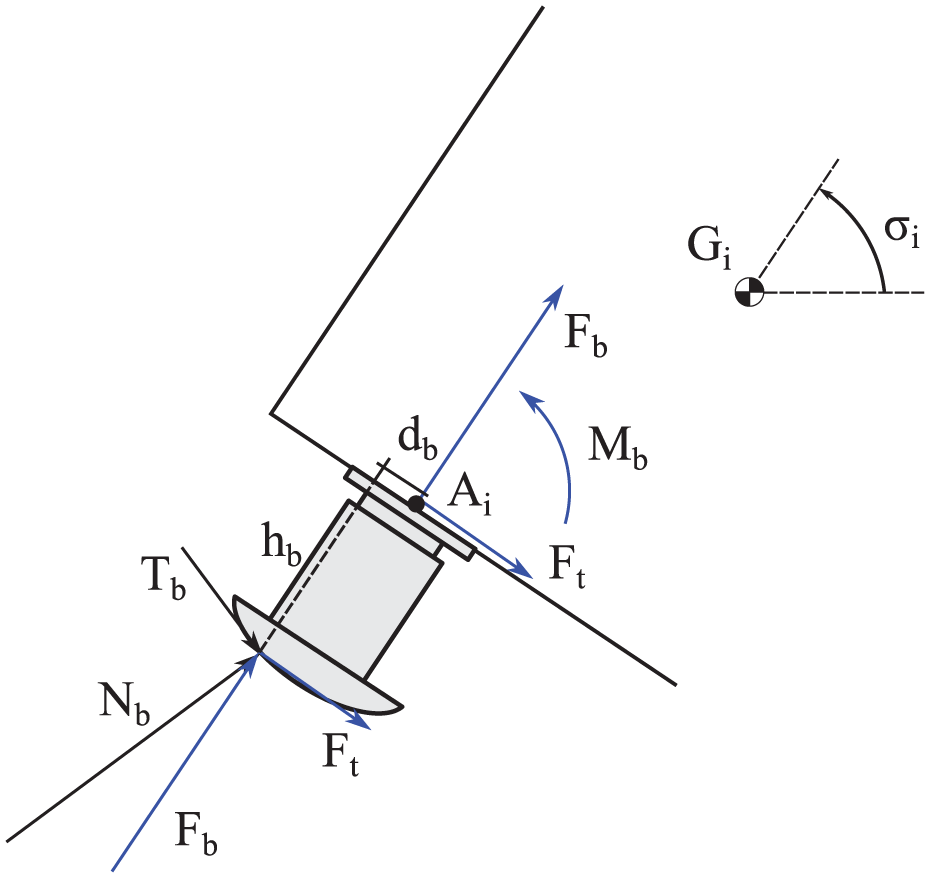
Forces acting on the buffer.
In particular,

Where
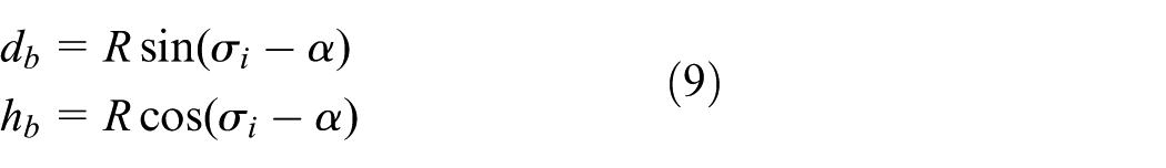
Knowing F b at each time step of the simulation, it is possible to compute N b and consequently T b as:

Analogously, it is possible to define the transversal force acting on the buffer as a function of

To define the vector of generalized forces
To consider the change in the point of application of the two forces, the moment M b is introduced:

Finally, to determine during the simulations the actual value of the buffer displacement

These forces depend on the buffer’s displacements and their time derivatives and therefore can be expressed as:

Keeping in mind that the behaviour of each couple of buffers is defined using only one independent variable, the deformation of the buffer mounted on the following vehicle
Finally, applying Newton’s third law, it is possible to define a first order nonlinear differential equation in the unknown

A state equation in the form of equation (14) is added for each couple of buffers in contact to the equations of motion of the vehicle and numerically integrated together.
FEM models of the containment structures
This section describes the finite element models used to describe the dynamic behaviour of the containment structures impacted by the trainset. Two types of track-mounted SGMs are considered as shown in Figure 5: a DCW and a GR placed between the running rails.

Rear view of the vehicle in contact with the track-mounted containment devices: (a) DCW and (b) GR. In both figures, in red, is highlighted a potential contact point P defined on the vehicle.
The containment wall is modelled using rectangular Kirchhoff plate elements 29 assembled to form the overall structural model (see Figure 6) and the impact with the derailed trainset is modelled using a contact-impact model that accounts for the local stiffness of the structure, as presented in Santelia et al. 17 The equations of motion of the DCW are:

Where:
The GR is also described using a FE model, but in this case beam elements are used, considering for each nodal section the following three generalized coordinates:
Nodal sections of the FE model are positioned at all locations where the GR is connected to the sleepers, as shown in Figure 7. Additional nodal sections are placed between the sleepers so that the portion of the GR corresponding to one sleeper bay is divided into two elements. The lateral distance of the GR from the running rail can be adjusted to simulate different configurations. As a first tentative, it is assumed that the GR has the geometric and inertial characteristics of the 60E1 rail. The data of the GR model are reported in Table 1. In addition, the sleepers, where the GRs fastener are fixed, are considered rigidly attached to the ground. It should be noted that the assumption of a perfectly rigid connection between the sleepers and the ground represents an idealization of the real case. However, it is expected that the motion of the GR under the effect of the forces exchanged with the derailed wheel(s) is mostly determined by the bending deflection of the GR and by the deformation of the fasteners connecting the GR to the sleeper, whilst the movement of the sleeper would become relevant only in case the limit of friction at the interface between the sleeper and the ballast is reached so that the sleeper slides over the ballast bed. A future extension of the model could consist of considering a flexible connection between the sleeper and the ground, using a stiff spring connected to a slider under dry friction, setting the sliding threshold to a value that reproduces the maximum force transmissible in lateral direction between the sleeper and the ballast bed.

Portion of the FE model of the derailment containment wall DCW. The position of a candidate impact point P is shown by the red dot.

FE model of the guard rail GR. The position of a candidate impact point P is shown by the red dot.
Inertial and geometrical data of the GR.

The fasteners used to connect the GRs to the sleepers are assumed to be the standard ones used for the running rails in Italian HS lines. The decision to use standard rails and fasteners for the containment GRs is based on the fact that these are commonly employed by the infrastructure manager and can be easily adapted to the GRs. However, it should be noted that these elements are not optimized for this specific purpose. One of the objectives of this paper is to assess whether this standard GR configuration is adequate or specific modifications are required to ensure the correct behaviour of the GR in the event of a derailment.
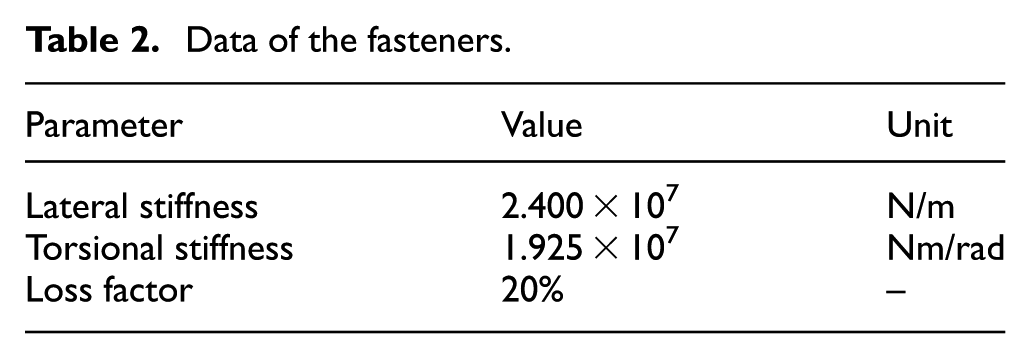
In the FE model, the fasteners are represented as viscoelastic elements located at the nodes of the beam corresponding to one sleeper. The lateral and torsional stiffness of the fasteners were determined from previous experimental tests and their values are provided in Table 2. A 20% loss factor is assumed to account for energy dissipation effects in the fasteners.
Data of the fasteners.
The contact force between the wheel and the GR is introduced using the Lankarani–Nikravesh model,
30
which was previously applied to model the impact between the trainset and the containment wall.
17
The model proposed defines a-priori some potential contact points belonging to different bodies of the trainset that could come into contact with the containment structure. During the simulation, the trajectory of this point is evaluated at each time-step and the interpenetration
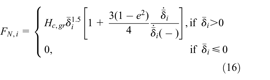
Where
To determine the local contact stiffness parameter
Validation
The proposed multibody model has been validated under different scenarios, through comparisons with other numerical models and with experiments. The results of these comparisons are reported in previously published papers, so we provide here a short outline of validation activities, pointing to the relevant references. First of all, the capability of the model to correctly predict the behaviour of the railway vehicle in standard running conditions was investigated by means of comparisons with numerical results obtained using the commercial software Simpack. These comparisons show very good agreement for the running of the vehicle in both large-radius and short-radius curves and allow to validate the vehicle model in the pre-derailment phase and the simplified wheel/rail contact model, see Santelia et al. 17 and Santelia. 31 The capability of the model to reproduce the impact with a SGM was assessed by comparing numerical results from the model to the results of a full-scale derailment experiment performed in South Korea, producing the impact of the derailed car against a kerb (a derailment containment provision placed between the running rails). 7 The results of these comparisons are reported in Santelia et al. 17 Finally, the ability of the model to correctly reproduce the interaction of the derailed vehicle with the sleepers and ballast was validated through comparisons with full-scale derailment tests performed in Italy on a freight wagon in tare and laden conditions. 32 The results, reported in Santelia et al., 17 show good agreement between the numerical and the experimental results in terms of the deceleration and distance to stop of the derailed wagon, confirming the ability of the model to consider the resistance effects arising in the contact between the derailed wheels and the infrastructure.
Simulations results
The scenarios investigated in this paper consider a complete trainset composed by 13 ETR500-class vehicles: two locomotives and 11 passenger cars. The track layout considered corresponds to the geometry of the curves most frequently occurring in the Italian HS network and consists of an initial 50-meter straight track used to initialize the motion of the trainset, followed by an entry transition with length 330 m and by a full curve section with radius 5450 m. In all simulation cases presented in this paper, a left bending curve is considered and the derailment is assumed to be caused by the failure of the axle of the trailing wheelset of the front bogie in the leading locomotive, occurring at the inner axle- box set while the trainset is travelling at the maximum service speed of 300 km/h. This failure was previously identified as the one producing the most severe outcome in terms of energy associated with the derailment and movement of the derailed vehicle. 17
The main objectives of the simulation cases presented here are on one hand to assess the effect of considering the complete trainset in place of a single vehicle and, on the other hand, to compare the performances of the derailment containment provisions considered in this study, that is, the DCW and the GR.
The presentation of simulation results focusses on the first two vehicles composing the trainset, that is, the leading locomotive which, due to the mechanical failure of the axle, undergoes the derailment and the first passenger car which does not derail but interacts with the locomotive through the coupling system. It is worth pointing out that in the simulations presented no traction and/or braking forces are considered for the entire trainset.
Trainset derailment and impact with the DCW
In the first proposed simulation case the derailed trainset is contained by a DCW. During the derailment process, the locomotive derails on the left-hand curve and moves to the right side of the track towards the DCW. Since one of the main focusses of this research is to assess the contribution of the coupling devices during the derailment event, Figure 8 shows the elongations and compressions of the screw coupler and buffers connecting the locomotive with the first passenger car. The axle failure takes place at time t = 15 s.

Elongation and exchanged force in longitudinal direction of the coupling devices between the locomotive and the first passenger car. Positive elongations and forces denote a traction state.
Before the failure, the coupling system shows the typical behaviour corresponding to the negotiation of a large-radius curve: during the straight section of the track (0–0.6 s, or the first 50 m), the preload force of the screw coupler Fh,p = 50 kN is balanced by two equal repulsion forces at the two buffers. Then, in the entry transition and full curve section before the failure (0.6–15 s), the left buffer experiences increased compression while the right buffer is slightly unloaded due to the relative yaw rotation of the two car bodies connected.
After the axle failure, the coupling system exhibits a typical behaviour with large variations of the forces at the screw coupler and buffers. In particular, the force exchanged between the left pair of buffers decreases. By around 16.5 s, this force drops to zero, indicating that the left- side buffers are no longer in contact. At the same time, the right-side buffers increase their state of compression and the exchanged force.
It is also important to mention that during the simulation the possible failure of the screw coupler is continuously checked by comparing at each time step the traction force in the screw coupler to the maximum force bearable by this element, but this limit load is never exceeded and therefore there is no intervention of the emergency braking system.
Figure 9 shows the position of the screw coupler and buffers connecting the first two vehicles of the trainset for the following selected times:
t = 1 s, train in the straight section of the track (Figure 9(a)).
t = 10 s, train in the full-curve section, before the axle failure (Figure 9(b)).
t = 15 s, immediately before the axle failure (Figure 9(c)).
t = 17.5 s, during the derailment phase when the maximum relative displacement between the two vehicles is reached (Figure 9(d)).
Figure 10 presents the instantaneous position of the leading locomotive and neighbouring passenger cars at t = 17.5 s, after the derailment and while the locomotive is in contact with the DCW (not shown in the figure). At this time, the left couple of buffers (red dot in Figure 10(b)) is no longer in contact, whilst the compressive force generated by the right couple of buffers (blue dot in the same figure) produces a yaw moment on the locomotive car body that re-aligns the vehicle to the local tangential direction of the curve, producing a more favourable angle of impact with the DCW, thereby reducing the severity of the impact. It should be noted that this effect is not accounted for by a model considering only the single derailed vehicle, as in Santelia et al.17,18

(a–d) Position of the coupling system between the first and the second vehicle of the trainset at different times.
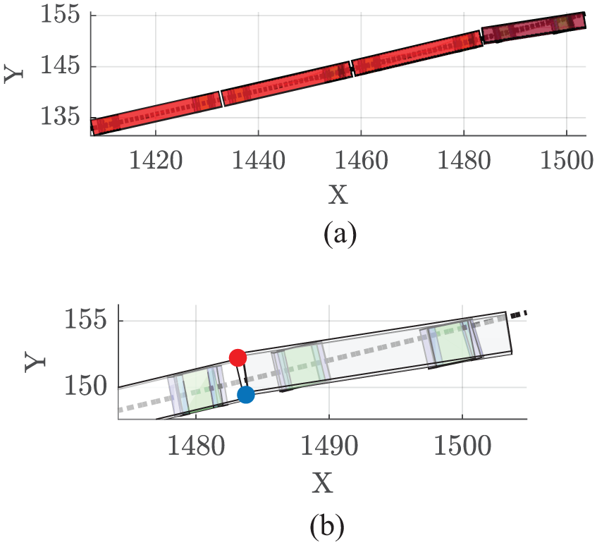
Position of the first part of the trainset at t = 17.5 s. (a) Top-view, (b) zoomed top-view showing the first two vehicles, the buffers are marked by a red and blue dot for the left and right side, respectively.
Figure 11 compares the impact force between the derailed vehicle and the DCW for the simulation considering the entire trainset (Figure 11(a)) and for a simulation considering only the derailed vehicle, that is, the leading locomotive and neglecting the interaction with the other cars in the trainset caused by the coupling elements. This latter result is the same as presented in Santelia et al. 17 It is observed that the peak contact force is slightly reduced by ∼11% when the complete trainset is considered instead of the single locomotive, which is determined by the yaw moment due to the coupling devices mentioned above.

Impact force between the derailed vehicle and the DCW. (a) Result of the simulation considering the entire trainset. (b) Result of the simulation considering only the derailed locomotive.
Table 3 compares the results of the simulations considering the isolated locomotive and the entire trainset in terms of the peak impact force and bending moment, and also in terms of impact speed and yaw angle of the leading bogie. For the simulation considering the entire trainset, the yaw moment generated by the buffers reduces the impact speed by ∼10%, which is consistent with the reduction of the peak contact force. The yaw angle of the leading bogie is reduced by ∼57%, showing the effect of the buffers on the orientation of the derailed vehicle while it impacts the DCW.
Comparison of derailment simulation results between a single vehicle and a complete trainset.

Finally, a sensitivity analysis was performed to investigate the effect of using a simplified linearized model of the coupling system instead of the detailed one based on equations (3) and (5). To this aim, two different linearized models of the draw gear and buffer forces were considered:
lin1: using for both the draw gear and buffers the secant stiffness computed over a range of deformation ranging from the undeformed state to a maximum extension (for the draw gear) or compression (for the buffers) of 50 mm, which is approximately the maximum amount of deformation obtained for both the draw gear and buffers in the results of the baseline simulation case using a non-linear model of the coupling system (see Figure 8).
lin2: same as lin1 but using for the draw gear and buffers the secant stiffnesses computed between the undeformed state and a maximum deformation of ±25 mm which, compared to lin1 provides a better agreement with the non-linear force versus deformation curve at small values of draw gear/buffer deformation, that is, in the initial phase of the derailment.
The results obtained using the two linearized models of the coupling system show a high sensitivity of the results to the simplified model adopted: using model lin1 after the axle failure the lateral and yaw movement of the locomotive is heavily constrained by the stiff connection with the neighbouring car, so that the derailment of the bogie with the broken axle does not occur and hence the locomotive does not impact the DCW. On the contrary, if the lowest secant stiffness lin2 is used, the derailment of the locomotive occurs and the maximum impact force on the DCW is 640 kN, nearly 20% larger than the value (540 kN) found using the non-linear force versus deformation curve.
Trainset derailment with a guard rail
The second simulation scenario considers the same track layout, trainset, and running conditions as the previous one, but the track-mounted SGM considered in this case is a GR mounted between the running rails. For this scenario, a sensitivity analysis is performed on the lateral distance of the GR from the inner rail. In particular, four configurations of the GR are considered: at the track centreline and at distances of 150, 250, and 350 mm from the track centreline, moving toward the inner rail. A minimum distance of at least 400 mm is maintained between the GR and the inner rail to ensure that the inner wheel of the derailed wheelset(s) remains confined between these two rails after the derailment. This spacing prevents the wheel from overrunning the GR and ensures that it falls appropriately between the running rail and the GR.
Figure 12 shows the time history of the impact force between the leading wheelset of the locomotive’s front bogie and the GR. A first peak with 538 kN amplitude is observed at ∼16.6 s, that is, 1.6 s after the failure of the axle of the second wheelset. After this first peak, the wheel shortly loses contact with the GR and then a second impact occurs, this time the peak force being ∼200 kN.

Time history of the impact force between the inner wheel of the first wheelset and the guard rail GR.
After the second impact, the contact between the inner face of the wheel and the GR is steadily maintained, due to the centrifugal effect acting on the locomotive. This produces an energy dissipation in the system, reducing the vehicle’s speed. As a result, the centrifugal effect on the locomotive decreases, leading to a reduction in the force between the wheel and the GR.
Other important outputs of the simulation are the forces exchanged between the GR and the sleepers at the fasteners. Figure 13(a) shows the time history of the lateral force at the fastener closest to the location of the first impact of the derailed wheel with the GR. The peak corresponding to the initial impact is clearly recognizable. Figure 13(b) displays the maximum value of the lateral force transmitted at all fasteners, as function of the fasteners’ position. The location of the first impact is shown by a red vertical line: it is clear from this diagram that the impact force applied by the derailed wheelset to the GR is mostly carried by the 8 ÷ 10 fasteners located around the position of the point of first impact. The transmitted force reaches large values also at some other fasteners located after the point of first impact, due to the second impact and then continuous contact of the derailed wheelset with the GR.
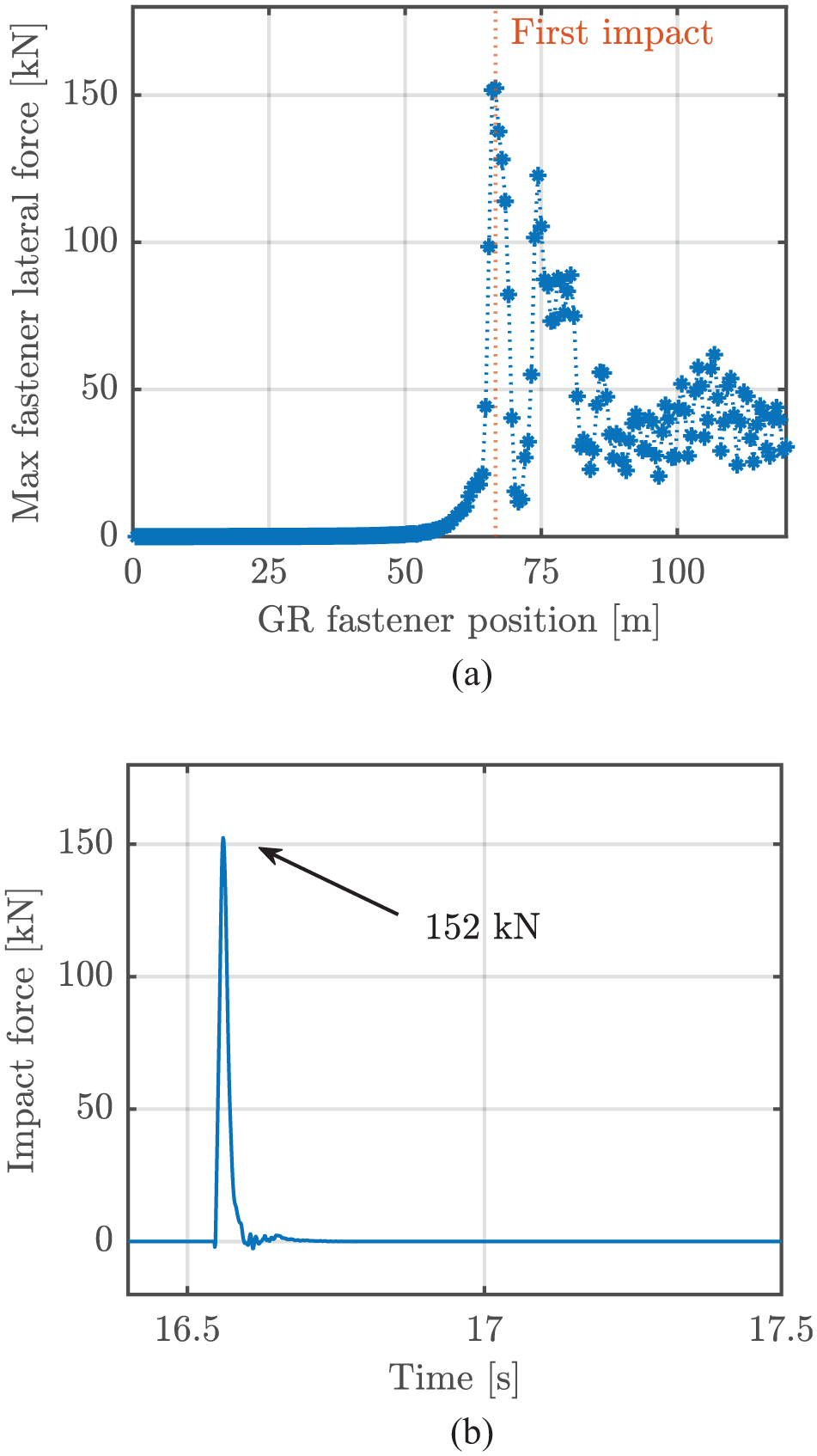
(a) Maximum lateral force on the guard rail GR fasteners plotted versus their position in the guard rail GR reference system and (b) Time history of the lateral force applied on the guard rail GR fastener closest to point of first impact with the derailed wheel.
In this second scenario with the GR as the considered track-mounted SGM, the focus is on the lateral force that the fasteners need to withstand when the GR is impacted by the wheels of the vehicle, because the fasteners are the weakest part of the structure.
A sensitivity analysis is conducted on the maximum impact force and the maximum lateral force transmitted by the fastener as a function of the distance of the GR from the track centreline, considering the following distance values: 0, 150, 250, and 350 mm. The results of this parametric analysis are shown in Figure 14, both for a simulation considering the complete trainset (solid lines) and for one considering the single locomotive (dashed lines). Considering the complete trainset, the maximum impact force varies between 560 and 120 kN, the lowest value occurring when the GR is at 350 mm from the track centreline, that is, the position closest to the derailed wheel among all those considered in the analysis. The trend of the maximum force with the distance from the track centreline is nearly monotonic for the two cases of the complete trainset and single locomotive, highlighting the strong influence of the distance of the containment device on the peak force generated by the impact of the derailed wheel with the GR.

Maximum impact force (blue lines) and maximum lateral force on the fasteners (red lines) considering the complete trainset (solid lines) and the single locomotive (dashed lines) plotted versus the distance of the guard rail GR from the track centreline.
The maximum values of the lateral forces transmitted by the fasteners, also reported in Figure 14, show a similar trend, with the maximum force being much smaller for the two locations closest to the running rail on the side of the derailed wheel. The same trend, both for the maximum impact force and maximum lateral force exerted on the fasteners is obtained from the simulations considering a single locomotive, but in this case the fastener force is slightly lower for the GR distance of 250 instead of 350 mm. This result highlights again the consistent relationship between the guard rail position, the maximum value of the impact force and the maximum lateral force on the fasteners. The trend of the impact force with the distance of the GR from the running rail found for both the complete trainset and the isolated locomotive is justified by the fact that, for a position of the GR closer the running rail, the derailed wheel has less time to gain speed in radial direction and therefore the impact speed is decreased, as shown in Table 4.
Sensitivity analysis on the maximum impact force and maximum corresponding lateral force on the fasteners versus the distance of the GR from the track centreline.

Finally, the maximum lateral forces transmitted by the fasteners, as obtained from the simulations, shall be compared with the shear and axial resistance of the fastening systems connecting the GR and the sleepers. This comparison is crucial for determining whether standard fasteners can be used for GRs. The most critical component of the fastening system is the plastic dowel embedded in the concrete sleeper, which, together with the corresponding bolt, provides the anchoring force for the fastener and, by extension, for the GR.
Indeed, inspections of the track showed that dowels may suffer damage or failure due to train loads and environmental conditions. Experimental tests also indicate that, under intense and prolonged pull-out forces, the first element of the bolt anchorage to fail is typically the thread of the plastic dowel within the concrete sleeper.
In general, these components are subjected to qualification tests before being approved for use in service and one specific test for evaluating the dowel-bolt connection in rail fastenings is the pull-out test. This test is performed in compliance with European standards33,34 to verify that the force required to extract the anchorage of a rail fastener assembly from the concrete sleeper is above a prescribed threshold. is reached. At this stage, the fastening system is inspected to ensure that there is no evidence of damage that could compromise its strength or durability. The value of “proof load” applied during the validation tests is prescribed by European standards 34 and is equal to 60 kN for cast-in fastening components.
However, the normed pull-out test is intended to reproduce standard operational conditions to evaluate the reliability of the fastening system and, consistently, the value of the “proof load” is relatively low, to represent a pull force that may act repeatedly on the fastener anchor. Instead, when a derailment event is considered, the limit value of the pull-out force should be set to a higher value, corresponding to the exceptional case of the derailment, to check that the anchor can withstand this extreme loading condition at least once in its service life.
In Chen et al., 35 a series of pull-out and pre-tightening tests on the bolt and plastic dowel connection were conducted to establish the relationship between the bolt’s ultimate pull- out force and the effective anchorage length, to analyze the failure mechanisms of the plastic dowel, and to examine the relationship between pre-tightening force and installation torque. Under optimal conditions, it was found that for the maximum effective fastening length of 730 mm, the maximum pull-out load is 130 kN.
Finally, to evaluate whether standard fasteners are sufficiently reliable to be adopted as guard rail GR fastening systems, it is helpful to refer to Figure 15. This schematic illustrates the forces generated during impact, specifically the lateral component

Assuming a maximum pull-out resistance force N lim of 100 kN as the threshold (considering a 30% safety factor with respect to the ultimate pull-out force found in Chen et al., 35 the maximum lateral impact force F that the fastening system can withstand can be evaluated rearranging equation (17) as:

If the impact forces resulting from the simulations exceed this threshold (F max ), the pull-out resistance of the fastening system is deemed compromised.
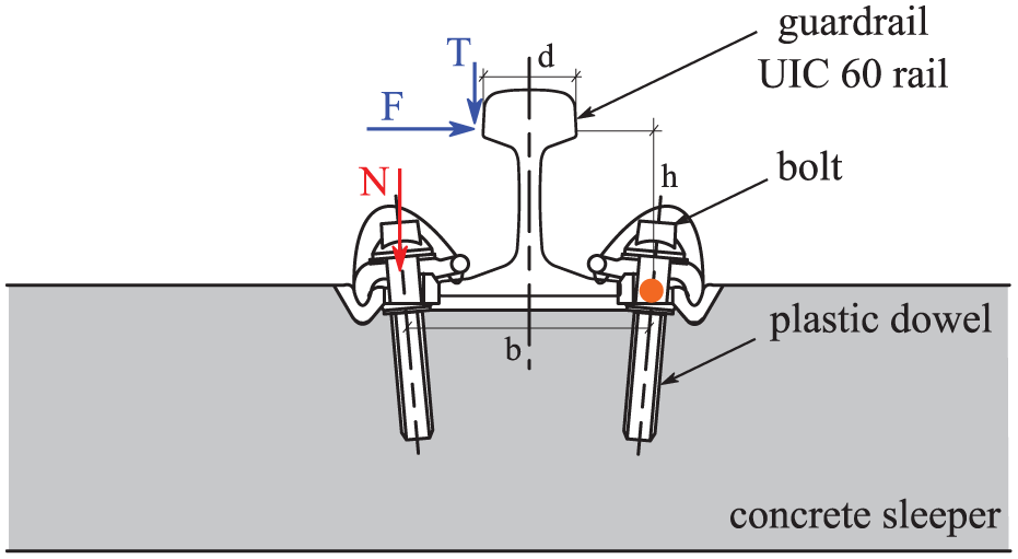
Scheme of the forces acting on the fastener.
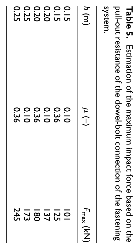
Comparing the data in Table 5 with the maximum impact forces obtained from simulations reported in Table 4, it is found that, unless the GR is located at 350 mm from the track centreline, at least two dowels per side are required, along with a sufficiently wide fastener base. It is important to note, however, that the fasteners must be properly designed to account for the complexity of the stress state, which includes significant shear forces, as well as the geometry of the components used. In other words, the data in Table 5 can serve as a basis for preliminary calculations, but a more precise and detailed study is recommended to ensure the proper sizing of the fasteners.
Estimation of the maximum impact force based on the pull-out resistance of the dowel-bolt connection of the fastening system.
Conclusions
In this paper a multibody model to study the post-derailment dynamics of a railway vehicle, proposed in Santelia et al. 17 has been extended by modelling the entire trainset, considering the interaction between adjacent vehicles through the coupling system and including the model of a new containment device: the GR. This multibody model is developed to simulate various derailment scenarios and the resulting interaction between the derailed vehicle(s) and the containment device (either a DCW or GR), in order to support its structural design and sizing.
This research is particularly relevant in the field of railway safety, not only within the academic community but also for the railway industry, as it addresses the need to identify derailment mitigation measures that are effective while not being overly massive or expensive, and can be implemented on railway lines with a reasonable effort from infrastructure managers. In fact, at present no clear standard exists on how to design track-based containment devices or on which solutions are most suitable for different scenarios.
The outcomes of this study are expected to provide infrastructure managers with valuable insights to support informed decisions on the implementation of containment devices, while also fostering the adoption of standard safety practices across the railway industry. The growing importance of this research area is also demonstrated by several ongoing initiatives in both academia and the railway industry. On the scientific side, recent review studies such as Tang et al. 5 are consolidating the existing knowledge on derailment dynamics and mitigation strategies. On the industrial side, a clear example is the MITIG4DERAIL projects led by UIC, supported by a wide consortium of infrastructure managers, intended to harmonize methodology for design of derailment mitigation measures and study the effectiveness of measures in use. 36
In this context, the first set of results presented in this paper consider the use of a DCW as the consider SGM and focus on the effect of considering the entire trainset instead of a single vehicle. Simulation results reveal that the forces exchanged through the coupling system significantly affect the dynamics of the derailed vehicle, and particularly the impact forces exerted on the containment device. It has been shown that the post-derailment dynamics is modified by the yaw moment induced by the coupling forces. Specifically, the buffer located at the outer side of the curve undergoes a compression state, thereby tending to realign the derailed locomotive with the second vehicle in the trainset and results in a reduction of the impact force applied to the containment device.
The second set of results focusses on simulations involving the GR as an alternative SGM. Positioned between the rails, the GR is designed to intercept the inner wheel of derailed wheelsets, preventing excessive lateral movement from the track centreline. The GR is modelled using beam finite element elements connected to the ground by discretely-spaced viscoelastic elements representing the fasteners connecting the GR to the sleepers.
To evaluate the effectiveness of the guard rail GR in confining the lateral motion of the derailed vehicle, numerical simulations were performed for both the single derailing locomotive and the complete trainset, considering different positions of the guardrail with respect to the track centreline. These simulations were used to assess the GR’s containment capability, estimate the maximum wheel-to- GR impact forces, and estimate the peak values of the forces transmitted through the fasteners. The results indicate that positioning the guardrail closer to the inner rail reduces both the impact forces applied to the GR and the forces transmitted through the fasteners. The predicted impact forces range from 119 to 564 kN, depending on the lateral GR position and on whether the simulation involves a single vehicle or the entire trainset. Correspondingly, the maximum forces transmitted by an individual fastener range from 65 to 176 kN.
Finally, a preliminary analysis of fastener resistance to the impact was performed based on an estimate of the fastener’s pull-out resistance derived from tests of standard dowels- bolt connection. This analysis suggests that, except in case the GR is located as close as possible to the running rail (therefore eccentric with respect to the track centreline) at least two bolts per side are needed to ensure the resistance of the fastening system to the forces generated by the impact with the derailed wheelset. However, a more detailed analysis is necessary to properly size the fastening system, as failure in these components along the GR would reduce its lateral resistance and containment capability. The results of the analysis also show that the GR should be installed close to the inner rail, while ensuring adequate space for the wheel to fall between the rail and the GR.
Given the challenges identified in using this device, further parametric analyses are recommended to explore its applicability under different operational conditions. This study represents a starting point for refining the GR’s design and ensure its reliability in a broader range of scenarios. Additionally, the proposed model offers practical insight to compare different SGMs.
Footnotes
Handling Editor: Sharmili Pandian
Funding
The authors received no financial support for the research, authorship, and/or publication of this article.
Declaration of conflicting interests
The authors declared no potential conflicts of interest with respect to the research, authorship, and/or publication of this article.