
Abstract
With the increasing incidence of injuries from automobile side-impact collisions, it is critical to investigate occupant biomechanical responses, particularly in the shoulder, abdominal, and pelvis regions. This study simulates side intrusion impacts on the rear door interior panel assembly using HyperMesh for pre-processing and LS-DYNA as the dynamic solver. The analysis examines the effects of different collision regions on occupant injury metrics and transient impact forces. Results show that maximum impact forces in the abdominal region exceed 2 kN, whereas forces in the pelvis region remain below 2 kN at a deformation of 15 mm. The failure of plastic clips securing the interior panels can lead to panel detachment, which directly strikes the occupant and increases the risk of injury. A structural optimization of the panel fasteners was proposed, enhancing both connection strength and energy absorption. The improved design prevents detachment during side impacts and ensures that all measured forces remain within safety thresholds. These findings provide a foundation for improving the structural integrity and crashworthiness of automotive door interior panels, thereby enhancing occupant safety in side collisions.
Introduction
Road traffic accidents can generally be classified into four main types: frontal, side, rear-end, and other types of collisions. According to accident statistics,1,2 side collisions account for approximately 35% of all cases, second only to frontal impacts. Unlike frontal and rear-end crashes, where airbags and seatbelts provide restraint, side-impact protection in passenger cars is usually limited to seatbelts, resulting in a higher fatality rate. In China, most urban intersections are flat, which further increases the incidence of side impacts. Therefore, strengthening research on the safety of automobile side collisions is of great practical significance.
According to the time history of side collisions and the interaction between vehicles and occupants, the process can generally be divided into two stages: the first impact and the second impact. During the first impact, when an external object collides laterally with the vehicle, structural components such as the body sidewall and the door assembly undergo deformation to absorb the impact energy. This stage results in the compression and reduction of the occupant survival space, thereby causing potential injuries. The second impact is essentially an extension of the first impact, 3 its severity depends on the dynamics of the initial collision. In this stage, the occupant, due to inertia, comes into direct contact with the interior door panel, which becomes a primary source of injury.
Automotive researchers generally improve side-impact safety from two main perspectives: (1) Structural design of the vehicle sidewall, 4 in which the impact energy from the first impact stage is distributed along components such as the side beams, door anti-collision beams, 5 and B-pillar, 6 thereby minimizing deformation of the sidewall and door assembly and protecting the occupant survival space; and (2) Occupant side restraint systems, 7 including side airbags and curtain airbags, which aim to prevent direct contact between the occupant and the door panel during the second impact, thus reducing injury severity. However, due to cost constraints and the non-mandatory nature of these safety regulations, side and curtain airbags are often optional in entry-level models. Therefore, in vehicles lacking such systems, enhancing the energy-absorbing performance and structural integrity of the door trim panel during the second impact represents an effective strategy to meet mandatory side-impact safety requirements.
Side-impact of the door involves a nonlinear, large-deformation energy absorption process, including collapse, instability, bending failure, and tearing of thin-walled sheet metal and plastic components. Conducting physical experiments to study these processes is both time-consuming and costly. Therefore, understanding how the vehicle body structure affects side-collision safety during the early design phase is crucial. Fortunately, finite element method (FEM)–based approaches, combined with well-defined material properties and accurate numerical models, provide a reliable alternative to physical testing, enabling the simulation of complex side-impact behavior and supporting the design of safer vehicle structures.
In side-impact simulations, numerous nonlinear factors, including geometry, material properties, contact conditions, and friction, must be considered, making the establishment and solution of the motion equations highly complex. Current research on door collisions primarily focuses on stress distribution,8–10 intrusion magnitude, energy absorption curves, acceleration, and dummy injury metrics, providing a foundation for improving vehicle safety design. For example, Sharma 11 employed finite element analysis to investigate the static and dynamic behavior of B-pillars and anti-intrusion beams with different cross sections under side-impact loading, identifying configurations that maximize energy absorption. Similarly, Xiao et al. 12 analyzed occupant chest injuries using FEM-based simulations of side collisions, demonstrating that seatbelts can effectively mitigate occupant injuries. These studies confirm that FEM is a powerful tool for predicting vehicle collision performance and guiding structural safety improvements.
The structure of a car door assembly is highly complex, 13 comprising multiple metal and polymer components, including inner and outer panels, interior trim, reinforcements, and fastening elements. Beak-type plastic clips connect the interior panel to the door metal structure, playing a critical role in maintaining assembly integrity during side impacts. The complexity of the assembly and the potential detachment of these clips during secondary collisions underscore the importance of detailed finite element analysis to evaluate occupant injury and guide design optimization.
While previous studies have primarily focused on stress distribution, energy absorption, and occupant injury metrics in side-impact scenarios, the present study specifically addresses the behavior of the door interior panel assembly under secondary side-impact conditions. In real-world collisions, plastic clips fastening the interior trim are prone to detachment, allowing the panel to rebound and potentially injure occupants—a mechanism largely overlooked in prior FEM-based studies. Using finite element simulations, this work analyzes the influence of different collision regions on occupant injury and investigates the failure mechanisms of the clips, thereby providing a direct link between fastener mechanics and occupant safety.
To address this issue, a detailed finite element model of the passenger car door was developed following GB20071-2006 14 and relevant industry standards. The model is used to simulate secondary side-impact scenarios and evaluate the mechanical response of the interior panel and its fastening system. The findings of this study inform design optimization strategies aimed at preventing clip detachment, enhancing energy absorption, and improving overall occupant protection, while providing a theoretical basis for reducing the development cycle and cost of door interior panel design.
Side impact simulation model of door interior panel
Finite element model of collision
According to the China New Car Assessment Program (C-NCAP) side-impact requirements, 15 occupant injuries during a side collision are primarily concentrated in four regions: the head, chest, abdomen, and pelvis. 16 Since the head typically does not contact the door trim panel, the safety performance criteria for the door trim are mainly focused on protecting the chest, abdomen, and pelvis during side-impact events.
A rectangular coordinate system (X, Y, Z) was established in accordance with GB 20071-2006 and the three-dimensional vehicle model data. The sitting position of the EuroSID II side-impact dummy was adjusted based on the vehicle H-point, 17 and eight secondary impact points were defined, including one shoulder point, three abdominal points, and four pelvis points, as illustrated in Figure 1. The shoulder impact point is located at the rear end of the upper trim panel, the abdominal impact area at the rear end of the armrest, and the pelvis impact area at the rear end of the lower trim panel. To simulate the secondary collision, an iron cylinder with a diameter of 250 mm and a height of 100 mm was used to impact the interior panel, with an initial velocity of 3 m/s in the negative Y-direction. The cylinder was treated as a rigid body to reduce computational effort.

Interior panel impact position diagram.
To improve computational efficiency while maintaining accuracy, the door geometry was simplified by removing unnecessary features such as small bosses, microholes, and chamfers. The resulting finite element model of the car door is shown in Figure 2 and comprises a total of 249,902 elements, including 119,963 solid (volume) elements, 126,864 quadrilateral shell elements, and 2812 triangular shell elements. Triangular elements account for only 1.1% of the total (<5%), and all elements satisfy the relevant quality criteria. 18 A uniform mesh size of 8 mm was applied, with finer meshes employed for critical local details.

Finite element model of vehicle door in HyperMesh.
Vehicle door structures are typically joined using welding, bolts, and riveting. In the finite element model, bolt and rivet connections were represented using RBE2 rigid elements, while bonded regions were simulated using the volumetric Tied element method. Since the likelihood of solder joint detachment during a side-impact collision is minimal, rigid elements were employed to model the soldered connections. 19
Cable elements were used to model the door cable, which was connected to the armrest bracket through a radial spring with a stiffness of 0.1 kN/mm. Cable tension was simulated using a nonlinear spring with a pre-applied force. The door lock handle was attached to the interior panel via a rotatable beam element. The hot riveting structure was represented by hot pile solid elements linked to the corresponding nodes of the interior connecting holes, 20 with all elements satisfying the relevant failure criteria. To ensure both assembly convenience and fastening reliability, beak-type plastic clips at the front and rear lower edges were positioned near the panel boundaries with a spacing of approximately 75–85 mm, while the spacing at less critical locations was maintained below 220 mm, resulting in about eight clips along the side of the interior panel. Multiple-thickness elements were employed to accurately capture the geometric characteristics of the clip regions, 21 as illustrated in Figure 3.

Plastic clip model.
During an actual side-impact collision, both the door and the vehicle side-frame structure deform. However, when analyzing the side impact response of the interior panel, the deformation of the side frame is negligible compared with that of the interior panel. Therefore, fixed constraints were applied to all door locks and hinges, as shown in Figure 4. To better represent real-world conditions, gravity was applied to all components in the model.

Constraints of the car door model.
Materials
Based on the mechanical properties of the various door panel materials, appropriate LS-DYNA material models were assigned to each component. The door’ inner and outer panels, along with the reinforcing plates, are primarily made of hot-dip aluminum-zinc alloy steel and were modeled using the multi-segment linear plastic material model (MAT024). To reduce computational cost, the cylinder used for side-impact loading was assumed to be rigid, and its deformation was neglected; it was therefore simulated using the MAT20 rigid material model.
Considering the high-speed, dynamic nature of the door collision, the Cowper-Symonds constitutive model was employed to account for strain rate effects. 22 It can be written as:

Where
The interior panel assembly consists of various polymer components: the buckle is POM HOSTAFORM, the main panel body is PP-GF30, the door lock handle is nylon PA6, the interior handle and switch control box are PA6-G15, the switch panel is PC-ABS, and ABS is used for the embedded trim panel, upper trim panel, and armrest. The lower trim panel and map pocket are made of PP-BF1017. All components were modeled using the MAT89 material model, with parameters summarized in Table 1. To account for strain-rate-dependent behavior during impact, nonlinear real stress–strain curves at multiple strain rates were employed (Figures 5 and 6).
Material parameters of the interior panel parts.


Real stress-strain curves of materials at different strain rates: (a) PC-ABS and (b) ABS.

Real stress-strain curves of PP-BF1017 at different strain rates.
A soak anti-collision block is installed in the pelvis area of the lower trim plate to absorb side-impact energy and mitigate pelvis injuries. This energy-absorbing block was modeled using the MAT83 material, which is based on hyperelastic theory and describes the mechanical behavior of medium- to low-density recoverable foam with a default Poisson’s ratio of zero. The model incorporates stress–strain curves at different strain rates in tabular form and accounts for hysteresis during unloading by introducing elastic energy dissipation. The unloading curve

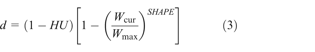
Where
Based on GB/T 8813-2008, the mechanical properties of the foam were characterized using a Universal Material Tester. Uniaxial compression and uniaxial tensile tests were conducted at three strain rates: 0.001, 0.01, and 0.1/s (Figure 7). The corresponding engineering stress–strain curves obtained for the foam at different strain rates are presented in Figure 8. Material parameters for the foam were then determined from these experimental results, with the main parameters summarized in Table 2.
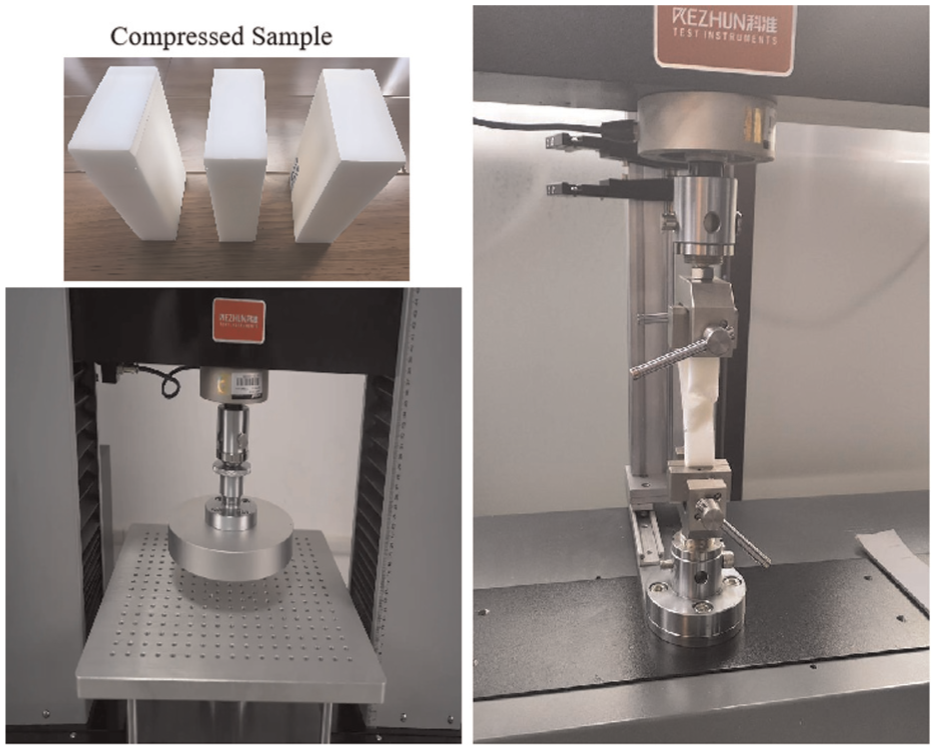
Mechanical performance test of foam.

Engineering strain curves at different strain rates: (a) compression and (b) stretching.
Main parameters of the foam material.
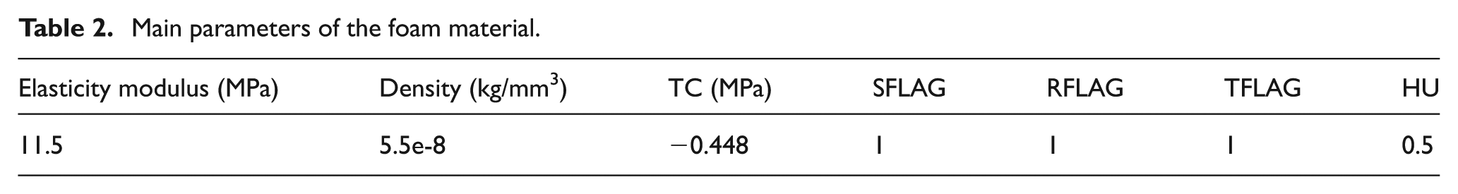
Where TC denotes the tensile cut-off stress, SFLAG represents the engineering strain rate, RFLAG specifies the evaluation criterion for strain rate, and TFLAG corresponds to the evaluation criterion for tensile stress. Setting SFLAG, RFLAG, and TFLAG all to 1 ensures that the numerical simulation fully incorporates the experimentally measured stress-strain curves, accurately capturing the foam material behavior under compression, unloading, and tension. This approach provides a realistic representation of the foam’s anisotropic, nonlinear, and hysteretic characteristics. HU is the hysteresis unloading factor, which takes a value between 0 and 1.
Selection of element types
LS-DYNA employs low-order linear elements. Compared with high-order elements in high-speed collision dynamics analyses, low-order linear elements offer advantages such as faster computation, stable performance under large deformations, and convenient handling of contact interactions at intermediate nodes. The rear door of the vehicle is constructed from multiple stamped and welded thin and thick plates. For the collision analysis, four-node Belytschko-Tsay shell elements are used, with single-point integration at the mid-surface and multiple-point integration through the shell thickness. 23
Contact settings
During the collision process, the contact interactions among components must be carefully modeled, as the various parts of the car door undergo compression and exert mutual forces, with the exact locations and directions of contact being difficult to predict. In LS-DYNA, the contact algorithm is based on the penalty method, which prevents penetration between components as well as within individual parts. Accordingly, surface-to-surface contact is defined between the impactor and the interior door panel, while single-surface contact is applied among the other door components. 24 Considering that the energy-absorbing block may fracture upon impact, erosive contact is introduced between the block and the lower trim plate, as well as between the block and the main body of the interior trim panel. Assembly clearances are taken into account for all contact pairs. 25 The boundary friction coefficient is set to 1.0, and the internal friction coefficient is set to 0.2. Additionally, the hourglass viscosity coefficient is assigned a value of 0.1. The model, with the specified contact definitions, is then exported as a K file and submitted to the LS-DYNA solver for computation.
Analysis of collision simulation results of interior trim panel
Interior panel side-impact assessment
The design requirements for the interior panels stipulate that, under the action of the impactor, the peak force in the target area within a specified collapse stroke must remain below a designated threshold. At the same time, the interior panel must remain intact, free from cracks, sharp edges, or other damage that could cause secondary injuries to occupants. Specifically, for shoulder impacts, the displacement must be limited to 15 mm with a maximum contact force not exceeding 3 kN. For abdominal impacts, the reaction force within a collapse stroke of 25 mm should not exceed 2 kN. For pelvis impacts, the reaction force within a displacement range of 15–40 mm is required to remain within 2–5 kN. Previous studies have shown that the secondary collision between the occupant and the interior panel typically occurs within 30 ms, covering the entire contact-to-separation process. 26 Therefore, the collision termination time is selected as 30 ms in this paper.
Figure 9 shows the force–displacement results for shoulder and abdominal impacts. For the shoulder impact, the maximum force within the first 15 mm of crush is 2.61 kN, satisfying the design criterion, with an absorbed energy of 12.8 J. However, beyond 40 mm of displacement, a sharp force increase (∼7 kN) is observed, indicating hard contact or bottoming between the trim substructure and a rigid feature.
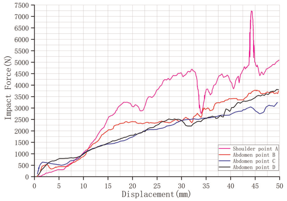
Shoulder and abdomen impact results.
For the abdominal impacts, the peak forces within the first 25 mm of crush are 2.41 kN at point B, 2.13 kN at point C, and 2.30 kN at point D—all exceeding the 2 kN limit and thus failing to meet the design requirements. This indicates excessive local stiffness in the armrest/abdomen contact zone. 27 Correspondingly, Figure 10 illustrates that, during the shoulder impact, noticeable indentation occurs at the contact area between the impactor and the door, accompanied by significant deformation in the fastening clip region behind it. In the abdominal impact at point B, the armrest exhibits local indentation, and the clip seat undergoes substantial deformation, consistent with real-world collision scenarios.
Impact strain contour: (a) shoulder point A and (b) abdomen point B.
The pelvis force-displacement responses are presented in Figure 11. Three distinct stages can be identified: (1) an initial elastic stage (<10 mm) with a steep force rise following Hooke’s law; (2) a transitional stage (10–30 mm) characterized by local yielding and partial collapse, leading to a reduced slope; and (3) a later stage (>30 mm) with relatively stable growth, reflecting the residual load-bearing capacity of the trim. Despite this progressive behavior, the forces at 15 mm displacement remain below 2 kN, failing to satisfy the evaluation requirement. Nevertheless, the peak forces within the 15–40 mm range remain below 5 kN, thereby avoiding excessive localized loading. The insufficient early stiffness is identified as the primary shortcoming. Effective side-impact protection requires both adequate initial resistance to restrain pelvis intrusion and sustained energy absorption throughout the deformation range.
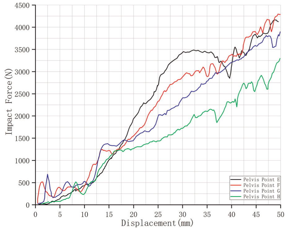
Pelvis impact results.
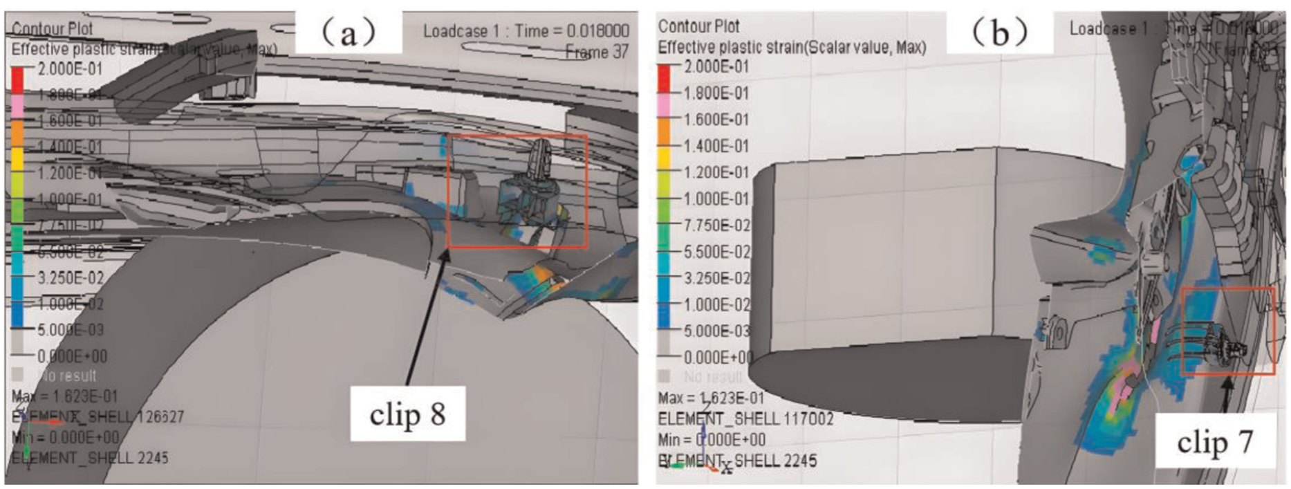
Figure 12 illustrates the deformation distribution of the lower trim panel under pelvis impacts. Since points E and F are located closer to the left side of the panel compared with point G, larger strains are observed on the left side during impacts at points E and F. By contrast, impact at point G results in higher strain at the bottom edge of the panel. Accordingly, the lower-left region of the trim panel should be designed with a large rounded arc surface to facilitate progressive deformation and enhance energy absorption during impact.

Pelvis impact strain contour: (a) point E, (b) point F, (c) point G, and (d) point H.
In summary, the shoulder impact performance meets the prescribed requirements, while the abdominal impact reveals excessive stiffness and non-compliance with force limits. The pelvis impact, although within the allowable force range, exhibits inadequate initial stiffness. These findings highlight the need for structural optimization of the door trim panel to balance energy absorption, stiffness distribution, and occupant protection across different impact zones.
Failure mechanism of plastic clips
The current industry requirement for the pull-out force of plastic clips used in door interior panels is 210 ± 10 N. 28 However, the impact forces generated during a collision can exceed this detachment resistance. As a result, clips may disengage from the sheet-metal holes, leading to partial detachment of the interior trim panel. Such detachment poses a direct threat to passenger safety, as the released panel may strike the occupant and cause secondary injuries.
To further investigate this issue, the sectional forces at the roots of the eight clips under impact loading were analyzed, with their positions illustrated in Figure 13. During the shoulder impact at point A (Figure 14), the maximum force on clip 8 reached 560 N, while the forces on the remaining clips remained below 150 N. Because impact point A is located adjacent to clip 8, the local strain in this region was significantly higher, leading to the largest clip load, as shown in Figure 10(a). As indicated in Figures 10(b) and 13, when the impact occurred at point B, located between clips 7 and 8, clip 7 sustained a peak load of 450 N, while clip 8 experienced 280 N. The forces on the other clips remained below the pull-out threshold. For abdominal impacts at points C and D, the maximum forces on clip 7 were 425 and 278 N, respectively, while all other clips satisfied the pull-out strength requirement.

Installation position diagram of the snaps.

Impact force of plastic clips: (a) shoulder impact point A, (b) abdominal impact point B, (c) abdominal impact point C, (d) abdominal impact point D, (e) pelvis impact point E, (f) pelvis impact point F, (g) pelvis impact point G, and (h) pelvis impact point H.
During pelvis impacts at points E, F, G, and H, as shown in Figure 12(b), the impact locations are close to clips 6 and 7. Consequently, the peak forces on clips 6 and 7 reached approximately 450 N, whereas the forces on the remaining clips were below the pull-out threshold. Specifically, clip 7 carried the larger load during the impact at point G, while clip 6 experienced the greater force during the impact at point H. These results indicate that the closer a clip is to the impact location, the greater its peak impact force. Overall, clips 6, 7, and 8 are the most prone to disengagement from the sheet-metal holes during collision, resulting in detachment of the interior trim panel and potential secondary injuries to the occupant.
Crash test evaluations have demonstrated that higher occupant protection scores are achieved when the door interior panel remains securely attached during side impacts, whereas panel detachment significantly increases the risk of collision-induced injuries and results in lower scores. These findings highlight the critical importance of enhancing the fixation strength of the door trim panel assembly. In particular, optimizing the design and mechanical performance of plastic clips is essential to prevent panel detachment under impact loading. Such improvements would contribute not only to maintaining the structural integrity of the interior panel assembly but also to reducing the likelihood of secondary injuries, thereby improving overall occupant safety during side impacts.
Interior trim panel optimization scheme
Structural modifications
Passenger injury during side impacts is closely related to the vehicle’s side structure. Adjusting the contact stiffness can effectively enhance side-impact safety performance. 29 In the abdominal side-impact region, due to the molding orientation of the center plate along the Y-direction, the ABS material of the center plate is relatively resistant to collapse, resulting in high impact forces. To improve this, a Z-direction core-pulling structure was introduced specifically at the abdominal contact area, 30 As illustrated in Figure 15, this region has been designed with a hexagonal honeycomb structure, featuring honeycomb ribs approximately 1.7 mm thick. The increased number of reinforcing ribs provides sufficient strength in the Z-direction, while allowing the honeycomb structure to collapse and deform under side impact, effectively absorbing energy.

Structural diagram of the interior panel.
The buffer space between the map pocket and the door metal plate has been enlarged in the pelvis side-impact region, 31 as shown in Figure 16. Simultaneously, the sidewall has been weakened by removing reinforcement behind it, 32 and the local wall thickness has been reduced from 2.5 to 2 mm. Consequently, the sidewall can easily fold and deform upon side impact. To further absorb impact energy, two weakening slots are incorporated behind the impact location.

Clearance between the map pocket and the door metal plate structure.
Anti-collision clips design
During a side impact, the rib cage—from the chest to the waist—is the most vulnerable region for occupant injury. 33 Based on the dummy sitting position model, the original plastic clips 6, 7, and 8 have been replaced with anti-collision clips 34 to prevent the interior panels in this area from disengaging and injuring the occupant’s body. The anti-collision clip consists of a snap, a snap base, a pull-ring latch (Figure 17). Under side-impact conditions, the applied force exceeds the detachment force of the plastic snap. As a result, the anti-collision snap is released outward, and the two semi-circular steel wires of the pull-ring latch slide along the conical head step and tightly secure the clip. This mechanism effectively prevents the interior panel from popping open and causing injury.

The composition of the anti-collision clip.
Simulation verification of optimized door structure
The optimized door structure was analyzed to evaluate its performance under side-impact conditions. The results indicate that the energy absorption capacity in the abdominal impact area has been significantly enhanced (Figure 18). For abdominal impact points B, C, and D, the peak forces within a collapse range of 25 mm are all below 2 kN, thereby satisfying the design requirements and effectively reducing the risk of excessive localized loading on the occupant’s abdomen. In the pelvis impact region, the peak force within 40 mm of displacement increased compared with the pre-optimization model, indicating an improvement in structural resistance. Meanwhile, the reaction forces within the critical displacement range of 15–40 mm remain consistently between 2 and 5 kN, which meets the regulatory evaluation criteria. This balance between increased resistance and controlled force transmission demonstrates that the optimized structure can provide sufficient initial stiffness to restrain pelvic intrusion while maintaining a stable energy absorption process. Overall, the secondary impact forces for both the abdomen and pelvis comply with design specifications, confirming that the structural optimization achieves a significant protective effect. These results validate the effectiveness of the proposed design strategies, offering practical guidance for enhancing occupant safety in side collisions through targeted improvements of door interior panel assemblies.

Optimized side impact diagram: (a) abdominal and (b) pelvis.
Conclusion
The design of the door trim panel assembly must simultaneously satisfy side-impact safety regulations and structural stiffness requirements, while also reflecting the actual collision conditions of the vehicle. Based on the developed finite element model and optimization analysis, the following conclusions are drawn:
(1) A high-fidelity finite element model of the door interior panel assembly was established using HyperMesh preprocessing and foam material mechanical tests, and the secondary side-impact process was simulated in LS-DYNA. Results showed that although the shoulder region met safety criteria, the abdominal impact forces exceeded the 2 kN threshold and the pelvis exhibited insufficient initial stiffness. Furthermore, the clip forces (≈280–560 N) surpassed the detachment resistance (210 ± 10 N), leading to disengagement of clips 6–8. This detachment reduced energy absorption capacity and increased the risk of secondary injury to occupants.
(2) Structural optimization measures were proposed, including a honeycomb structure in the abdominal energy-absorbing block, enlarged clearance and weakening slots in the pelvis region, and the replacement of conventional clips with anti-collision clips. After optimization, the abdominal impact forces were reduced by about 18% and remained below 2 kN, pelvis forces were stabilized within the required 2–5 kN range, and clip detachment was eliminated. The interior trim panel maintained attachment throughout the impact, effectively absorbing secondary collision energy, delaying panel rebound, and enhancing side-impact safety.
(3) The proposed optimization strategy establishes a direct link between fastener mechanics and occupant protection, offering both theoretical guidance and practical reference for structural design of door interior trim panels. The approach can shorten development cycles, reduce costs, and improve safety performance, particularly in the design of economical passenger vehicles.
Footnotes
Handling Editor: Xiang Tian
Consent for publication
The manuscript doesn’t contain any individual person’s data in any form.
Author contributions
Funding
The authors disclosed receipt of the following financial support for the research, authorship, and/or publication of this article: This project was supported by the University-Industry Collaborative Education Program (22097131130520).
Declaration of conflicting interests
The authors declared no potential conflicts of interest with respect to the research, authorship, and/or publication of this article.
Data availability statement
Data is provided within the manuscript.