
Abstract
Accurate health-state estimation is critical for the reliable operation and maintenance of high-reliability equipment. However, intrinsic function–performance coupling can distort state evolution and reduce monitoring credibility. We introduce a coupling-aware framework that (i) detects and quantifies latent couplings with the Function Resonance Analysis Method (FRAM); (ii) embeds these effects as hidden variables in an augmented discrete state-space model; and (iii) performs Bayesian, real-time inference via a particle filter that remains stable under nonlinear, time-varying conditions. Applied to steam-turbine rotor monitoring, the method consistently tracks crack growth, lowers remaining-useful-life prediction error, and preserves estimation robustness when task loads or functional configurations shift. The results demonstrate its practicality for complex, strongly coupled systems and its potential for broader prognostics and health management applications.
Keywords
Highlights
FRAM-based structural model captures function–performance coupling in complex systems.
EM-based estimator infers coupling disturbances in real time.
Coupling-aware particle filter enables health monitoring under changing conditions.
Method boosts crack tracking and RUL prediction in a steam-turbine case.
Introduction
In high-stakes fields such as aerospace, advanced manufacturing, and national defense, equipment systems are subject to extreme operating conditions, high integration, and long service life requirements. These challenges place stringent demands on system reliability and operational robustness.1,2 Once a fault occurs in such high-reliability systems, the associated maintenance costs are typically high, and the resulting consequences may severely compromise safety. 3 Therefore, enhancing the system’s ability to autonomously sense, diagnose, and respond to potential failures has become essential for mission assurance and operational safety. Against this backdrop, health monitoring and condition assessment technologies have gained increasing attention as key enablers for maintaining system reliability.4,5 By enabling real-time perception of component states and dynamic evaluation of degradation trends, health monitoring systems support not only early fault detection and risk mitigation but also facilitate condition-based maintenance and lifecycle reliability management.6,7
In complex manufacturing and operational environments, the realization of system-level functions critically depends on the underlying performance of key hardware components.8–11 A strong interdependence exists between functional demands and hardware performance states.12,13 Accordingly, the health state estimation of critical performance indicators serves as a fundamental basis for determining whether the system can fulfill its functional objectives and for quantifying performance margins and operational reliability. 14 Accurate and timely estimation of component health conditions enhances risk awareness and failure anticipation, thereby supporting system optimization and reliability-oriented maintenance. This concept has already been successfully applied in the reliability analysis and optimization of fundamental hardware such as battery degradation systems and drivetrain structures.15,16 With increasing structural complexity and rising demands for functional continuity and intelligent sensing in modern systems, it has become a key research challenge to develop robust and adaptive state estimation mechanisms capable of coping with diverse and uncertain conditions. 17
In real-world applications, the relationship between system functionality and hardware performance is rarely static or one-to-one.18–20 Instead, it forms a complex, evolving network of dynamic interactions and mutual influence. Function–performance coupling is widely observed in multi-functional system operations, where concurrent task execution and shared resource dependencies may trigger abrupt load redistributions, performance bottlenecks, or state transitions. 21 These effects can disrupt the evolution of health-related state variables, adding nonlinearities and uncertainties that lead to emergent phenomena beyond conventional performance evaluation logic. 22 Under such conditions, traditional state estimation methods—typically built on assumptions of structural stability and parameter stationarity—are insufficient to address the dynamic perturbations introduced by coupling mechanisms. Unmodeled coupling effects may introduce systematic estimation bias, thereby compromising anomaly detection and risk identification. This issue becomes particularly critical in safety- and reliability-sensitive applications, where inaccurate estimation may mask latent failures and lead to misguided decisions. 23
Despite the increasing prominence of these challenges in engineering practice, existing health state estimation methods have seldom addressed the dynamic interference effects stemming from function–performance coupling. In recent years, coupling mechanisms have become a growing focus in system design and reliability modeling, with studies exploring the influence of functional dependencies on failure modes, propagation paths, and lifetime distributions. Contributions have included multi-functional failure modeling,24,25 coupling structure identification,26,27 and interference mechanism analysis, 28 providing valuable support for system architecture design and risk-informed decision-making. However, most of these approaches remain confined to static modeling paradigms and are predominantly applied at the design stage, lacking the capability to account for the dynamic impact of coupling during actual system operation. The Function Resonance Analysis Method (FRAM) is widely applied in manufacturing, maritime operations, and wind energy systems, providing insight into nonlinear dependencies and latent coupling paths in system behavior.29,30 Although traditional FRAM applications are largely qualitative and difficult to embed in dynamic state estimation frameworks, its advantages in structural dependency analysis offer a promising basis for developing coupling-aware health monitoring strategies. 31
Motivated by the above modeling challenges, this paper proposes a coupling-aware health state estimation and monitoring method based on the FRAM framework. The proposed approach first identifies and quantifies the dependencies between functional units and hardware components to construct a functional–structural coupling map and evaluate the degree of coupling-induced interference affecting each component. Based on this structure, a discrete-time state-space model incorporating explicit coupling disturbance terms is established to embed the effects of functional dynamics on hardware performance. A particle filtering algorithm is further employed to realize real-time state updates and robust estimation under dynamic disturbances. This method is particularly suitable for high-reliability systems with complex architectures and dynamically evolving coupling relationships, where traditional modeling approaches fall short in capturing unmodeled interference effects. The proposed framework significantly enhances estimation robustness and monitoring reliability under nonstationary operating conditions.
To ensure the operational stability and reliability of high-reliability equipment systems, health monitoring serves as a critical tool for tracking performance evolution and enabling early detection of degradation. However, in complex manufacturing scenarios, the dynamic interplay between system functions and hardware performance—known as function–performance coupling—often introduces latent disturbances that compromise the reliability of health monitoring outcomes. Addressing this challenge, this study develops a coupling-aware health state monitoring framework that explicitly models and compensates for such effects. The main contributions of this work are as follows:
A structural modeling approach is proposed to characterize function–performance coupling relationships in complex equipment systems. Based on the Function Resonance Analysis Method (FRAM), this approach identifies coupling units and quantifies dependency structures that impact health evolution.
A discrete state-space model incorporating coupling-induced disturbances is constructed, and an Expectation–Maximization (EM)-based estimation method is developed to infer these latent disturbances in real time. Compared to conventional methods, the proposed EM scheme simplifies the iterative estimation process, thereby enhancing computational efficiency and enabling real-time monitoring in reliability-critical applications.
A coupling-aware particle filtering algorithm is introduced, which integrates FRAM-based structural identification with Bayesian inference for robust, online health state estimation under evolving coupling conditions.
The effectiveness of the proposed method is validated through a case study on steam turbine rotor degradation monitoring. Results show accurate tracking of crack growth and improved remaining useful life (RUL) prediction, demonstrating the method’s practical value for health monitoring and reliability evaluation of strongly coupled systems.
The remainder of this paper is organized as follows. Section 2 introduces the theoretical foundations of function–performance coupling in high-reliability equipment and analyzes its impact on health monitoring and reliability assessment. Section 3 presents the proposed coupling-aware health state estimation framework, including FRAM-based structural modeling, EM-based disturbance inference, and particle filtering methods. Section 4 validates the proposed approach through a case study on steam turbine rotor monitoring, demonstrating its effectiveness in degradation tracking and remaining useful life prediction. Section 5 concludes the paper and outlines directions for future research.
Basics of functional–performance coupling for high reliability equipment
Impact of functional–performance structure on high-reliability equipment systems
In equipment systems, a function typically refers to the capability of a subsystem or component to perform a specific task, such as machining, cooling, actuation, or motion control. In contrast, performance describes the effectiveness of function execution, characterized by indicators such as precision, speed, reliability, or frequency stability. 32 Function is the primary purpose of system operation, while performance provides the measurable basis for assessing functional implementation. Whether a system can fulfill a given function fundamentally depends on whether the underlying hardware components still meet the required performance criteria. The interplay between function and performance is illustrated in Figure 1.

Function-driven pathway for hardware performance and reliability evaluation.
According to the Degradation Irreversibility Principle, once a key component begins to deteriorate, the process is unidirectional and non-reversible: the cumulative degradation cannot decrease under normal operation. Hence, the system state is expressed as:

where
The Parameter Uncertainty Principle recognizes that both the degradation parameter

To reflect manufacturing tolerances, environmental fluctuations, and modeling errors. Explicitly accounting for these distributions during state estimation and health prediction prevents random variability from being misidentified as anomalies, thus enhancing the robustness and stability of the estimation process.
Margin-Based Reliability Principle states that the ultimate goal of health assessment is not merely to obtain the current performance value but to evaluate the performance margin

A larger margin indicates greater resilience to further degradation or external disturbances, whereas a margin approaching zero signals imminent unavailability. Performance margin therefore serves as a key indicator of health status and forms the quantitative basis for subsequent reliability allocation and maintenance optimization. 33
In summary, the Degradation Irreversibility Principle guarantees the one-way nature of performance evolution, the Parameter Uncertainty Principle captures the statistical variability of degradation and operating parameters, and the Margin-Based Reliability Principle maps performance outcomes to the reliability-decision space. Collectively, these three principles establish an interpretable pathway from functional requirements → performance dynamics → margin assessment → reliability allocation. This pathway provides both theoretical support and practical guidance for health monitoring, state estimation, and reliability analysis in highly coupled and highly uncertain environments.
Functional–performance coupling effects on monitoring
In practical engineering systems, the relationship between function and performance is rarely a stable one-to-one mapping; instead, it often exhibits cross-level, many-to-many coupling characteristics. As illustrated in Figure 2, a system-level function can be decomposed into multiple functional units at the equipment level. These functional units, through complex dependency and coordination relationships, map onto several basic components in the structural domain. Within this domain, the performance state of a single component may simultaneously support the realization of multiple functions, while the execution of a given function may likewise depend on the coordinated response of several components. Such many-to-many connectivity overturns the traditional “single-function–single-performance-metric” monitoring logic and gives rise to a nonlinear, dynamically coupled function–performance network.

Hardware performance monitoring framework with function–performance coupling.
In practical engineering systems, the relationship between function and performance is highly coupled, making accurate monitoring of hardware-performance states in complex equipment particularly challenging. These challenges are concentrated in three areas:
Complex structural dependencies and hard-to-quantify coupling effects. Multifunctional tasks often influence a single hardware component in nonlinear, cross-level ways, leading to significant functional interference and response overlap in the structural domain. Traditional one-to-one function–performance mapping methods cannot model such interactions effectively.
Time-varying coupling disturbances beyond the reach of conventional models. Task switching and cooperative execution inject a latent disturbance term

where
Lack of adaptive correction for coupling disturbances. Most existing state-monitoring approaches rely on static parameter models and thus cannot track the evolving behavior of coupling disturbances, leaving them incapable of robust estimation under changing coupling conditions.
To address these issues, a health monitoring mechanism that can sense function–performance coupling relationships and dynamically correct estimation bias is essential for improving adaptability and robustness in complex operating environments. Quantifying the strength of coupling and identifying interference pathways provide structural priors that enhance a model’s capability for accurate state estimation. At the same time, incorporating a coupling-disturbance estimation mechanism enables the state-evolution process to adapt to task switching and functional perturbations, allowing rapid correction of state deviations. By developing state estimation techniques that explicitly consider parameter uncertainty and operational disturbances, the system can achieve stable tracking of key hardware-performance states under multi-source perturbations. This not only improves monitoring robustness and adaptability but also provides trustworthy data for downstream reliability assessment, risk prediction, and maintenance strategy optimization.
Coupling-aware state estimation method for health monitoring of high reliability equipment
To mitigate the accuracy loss caused by function–performance coupling, this study proposes a concise three-step, coupling-aware state-estimation framework, as shown in Figure 3.
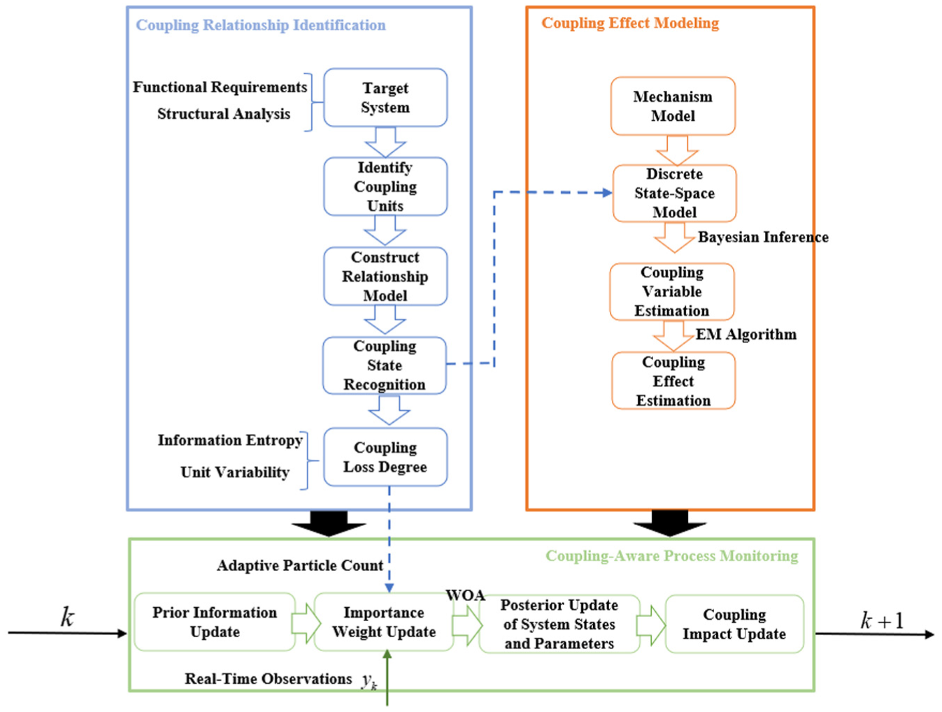
Hardware health-state monitoring framework with coupling awareness.
First, potential function–performance links are identified with the Function Resonance Analysis Method (FRAM) and their structural complexity is quantified via entropy metrics.
Second, these insights feed a discrete-time state-space model in which a latent coupling disturbance
Third, a particle-filter-based Bayesian inference scheme jointly updates
FRAM-based coupling relationship identification and quantification method
The coupling unit serves as the foundation for modeling the functional–performance coupling relationships of equipment based on the FRAM framework. It describes both the hardware structure and the system functions of the equipment.
Let the set of coupling units be defined as

Hexagonal feature representation of coupling units.
Each coupling unit is characterized by six functional aspects represented in a hexagonal structure: Input (I), Output (O), Precondition (P), Resource (R), Time (T), and Control (C). Input (I): Events or conditions that initiate the coupling relationship unit. Output (O): Processing results generated during the operation of the coupling relationship unit. Precondition (P): Necessary conditions for the unit’s operation, which do not directly trigger its initiation. Resource (R): Materials or information consumed or utilized during the unit’s operation. Time (T): Temporal constraints (e.g. sequence, duration) governing the execution of the unit. Control (C): Monitoring and control mechanisms regulating the operational process of the unit. Through structural and functional analysis of the equipment, the complete set of required system functions and supporting physical structures can be identified. By analyzing the relationships among hierarchical components and functions, the operational logic of the system is described. This enables the detailed mapping of how structures interact to fulfill designated functions and facilitates the identification of coupling units.
Coupling relationship modeling
Upon completing the identification and characterization of coupling units, this section considers the upstream and downstream relationships among units. Based on the FRAM framework, potential coupling relationships between units are represented. For any two units f
i
and f
j
, the coupling relationship is denoted as
To establish the network, it is assumed that if unit f i and unit f j share adjacent feature nodes, a directed edge l ij exists; otherwise, l ij = 0. Based on this criterion, a directed graph is constructed to represent the coupling relationships between functional units. The resulting FRAM-based network captures the functional–physical coupling structure of the equipment. In the subsequent analysis phase, the actual coupling relationships and directions are refined by examining the unit-level feature content in detail.
The functional–physical coupling network of the system can be formally defined as:

where f i denotes a coupling unit, l ij represents the coupling relationship between any two units f i and f j , and z ij indicates the weight of the coupling, reflecting the likelihood that unit fi induces a failure in unit f j .
Quantitative analysis of coupling unit variability
During system operation, the variability of coupling units must be considered with respect to both functional degradation and hardware stability. This study introduces a dual-dimensional variability characterization based on the FRAM framework, focusing on timing and precision attributes. The timing dimension reflects how early or late a functional impact occurs, while the precision dimension captures the clarity or ambiguity of that impact.
The timing variability of a coupling unit is denoted as
To fully exploit the analytical capability of FRAM in equipment-failure assessment—and to ensure the results faithfully mirror in-service behavior—an analytic hierarchy process (AHP) is incorporated to adjust the discrete probabilities associated with degradation and precision variability for each FRAM coupling unit. This adjustment quantifies the likelihood of different output variations within a coupling unit, thereby enhancing the specificity and accuracy of fault identification.
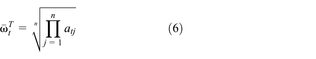
A pairwise-comparison judgement matrix is first established to rate the relative importance of the two variability factors; the numerical scale adopted is summarized in Table 1. Let a
tj
denote the element in row tth and column jth of this matrix. The corresponding priority (weight) vector is obtained by the geometric-mean method: the elements in each row are multiplied, the nth root of the product (n being the order of the matrix) is taken, and the resulting vector is normalized. The eigenvector derived for the degradation–variability dimension is denoted
Judgment matrix scale table.

After obtaining the feature importance vectors, normalization is performed to derive the relative weight of each variability factor, denoted as:

The variability of coupling unit f i , denoted as A i , is calculated as:

Where
To evaluate the coupling intensity of each unit based on upstream and downstream relationships, the degree of coupling DC i is defined as:

where l
ij
represents the directed coupling relationship from unit f
i
to unit f
j
If there is a direct link from f
i
to f
j
, then
According to the network topology, the extended centrality
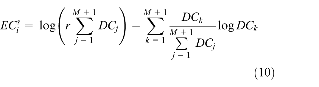

Where M is the number of first-order neighbors of unit f i . DC j denotes the degree of node j, DC k denotes the degree of node k, z ij represents the influence magnitude of coupling unit i on coupling unit j, and z ik represents the influence magnitude of coupling unit i on coupling unit k.
To further characterize the influence of coupling unit f i , its combined influence centrality is defined as EC i , calculated as:

where
Finally, by combining the influence centrality ECi, and variability

where A i is established through the Analytic Hierarchy Process. EC i is defined by the network topology. These measures remain invariant to changes in system parameters or operating conditions.
Coupling disturbance monitoring modeling and estimation method
Problem formulation under coupling disturbance
During manufacturing-system operation, the degradation evolution of critical components is commonly modeled and monitored with a discrete-time state-space framework, which simultaneously captures the temporal progression of system states and the dynamic input–output relationships. This approach has been widely adopted for degradation modeling, state estimation, and performance prediction tasks.34,35

In the discrete-time state-space formulation,
Because the present study does not consider explicit control commands

Although the disturbance
EM-based coupling-effect estimation
Conventional estimation schemes generally rely on a direct fit to the available observations. Once the coupling effect in a system has been partially identified or weakened, such data-driven methods often fail to deliver sufficient accuracy and cannot reveal latent coupling disturbances or their temporal evolution.
To overcome these limitations, this study adopts the Expectation–Maximization (EM) algorithm, which alternates between “latent-variable inference” (E-step) and “parameter update” (M-step). This iterative procedure is expressly suited to models that contain unobservable factors—such as the coupling-induced disturbance
In the E-step, the expectation of the complete-data log-likelihood is evaluated, yielding the so-called Q-function:

where
Here, a′ denotes the estimated coupling effect at the

By iteratively alternating between the two steps described above, the Q-function eventually converges to a local maximum. The convergence of the EM algorithm has been formally established in previous studies.
The Q-function typically involves the complete data log-likelihood, which requires modeling the entire history of the process. Based on the state-space formulation and the first-order Markov assumption, the complete-data likelihood is defined as:

Assuming conditional independence under the Markov property, the joint likelihood can be factorized as:

Thus, the Q-function can be rewritten as:

To simplify computation and avoid overfitting or divergence during iteration, a recursive estimation approach is adopted. Specifically, the estimation of

Because the coupling disturbance term

Let
Liu et al.
23
proposed a similar EM-based estimation scheme; however, their algorithm performs an exhaustive joint update over all state combinations, resulting in an overall computational complexity of
After the E-step has been completed, the algorithm proceeds to the M-step. The core objective in the M-step is to maximize the Q-function with respect to

In the proposed framework, the EM procedure operates on the posterior state distribution generated by a particle filter (PF), that is, jointly driven by FRAM-derived structural priors and a physics-based degradation model. These two sources of prior knowledge constrain the PF’s search space to physically plausible state trajectories, ensuring a stable and accurate posterior for the EM E-step. Given that the disturbance term is low-dimensional and structurally constrained, and that the PF-based posterior estimation is further refined via WOA, the overall disturbance estimation process inherits strong theoretical and practical convergence guarantees.
The M-step employs an adaptive gradient-descent algorithm as the numerical optimization method.
Health-state monitoring method based on particle filtering
During system operation, coupling effects or modeling errors may cause deviations in the state-evolution process, leading to large discrepancies between the true state and the measured outputs. To correct these deviations, this study applies a maximum-likelihood estimation scheme to jointly Infer the state variables and the associated latent disturbance. The procedure comprises two stages, as shown in Figure 5:
Generation stage (black solid arrows). Driven by the coupling disturbance
Inverse inference stage (blue dashed arrows). Given the observation sequence
Because

Forward state propagation and backward inference of coupling disturbance.
Particle filtering method
Particle filtering (PF) is a sequential Bayesian state-estimation technique built on the Monte-Carlo (bootstrap) framework. It is well suited to nonlinear, non-Gaussian systems with hidden states. The key idea is to approximate the posterior distribution of the system state by a set of weighted particles and to iteratively refine this approximation through a predict–update–resample cycle. The algorithm can be summarized as follows:
Initialization: Draw an initial particle set
State propagation (prediction) at time t: For each particle, generate a priori samples
Weight update (correction): Compute new importance weights according to the likelihood
Resampling: Draw a new particle set
The importance weights are obtained from the ratio between the true posterior and the importance density:
For computational simplicity one commonly selects

Finally, a standard resampling step is applied to eliminate particles with negligible weights and replicate those with high weights, after which each particle weight is reset to
Whale Optimization Algorithm (WOA)-enhanced particle filtering method
Because hardware degradation is highly stochastic—being influenced by ambient conditions, operating loads, and other factors—moving particles solely according to the state-transition equation cannot meet real-time requirements. To address this limitation, the present study incorporates a heuristic optimization strategy—the Whale Optimization Algorithm—to guide particle migration, thereby improving convergence speed and estimation accuracy. The resulting algorithm proceeds as follows:
In this chapter, each whale is treated as a particle in a given iteration, denoted

and a multi-step prediction vector:
Assuming Gaussian observation noise, equation (15) can be rewritten as:

Here,
The subsequent steps follow the canonical WOA procedure. After fitness evaluation, the algorithm adopts the standard search–update rules proposed: the control parameter
The overall workflow is illustrated in Figure 6.

WOA-based particle-optimization flowchart.
Coupling-aware particle-filtering monitoring method
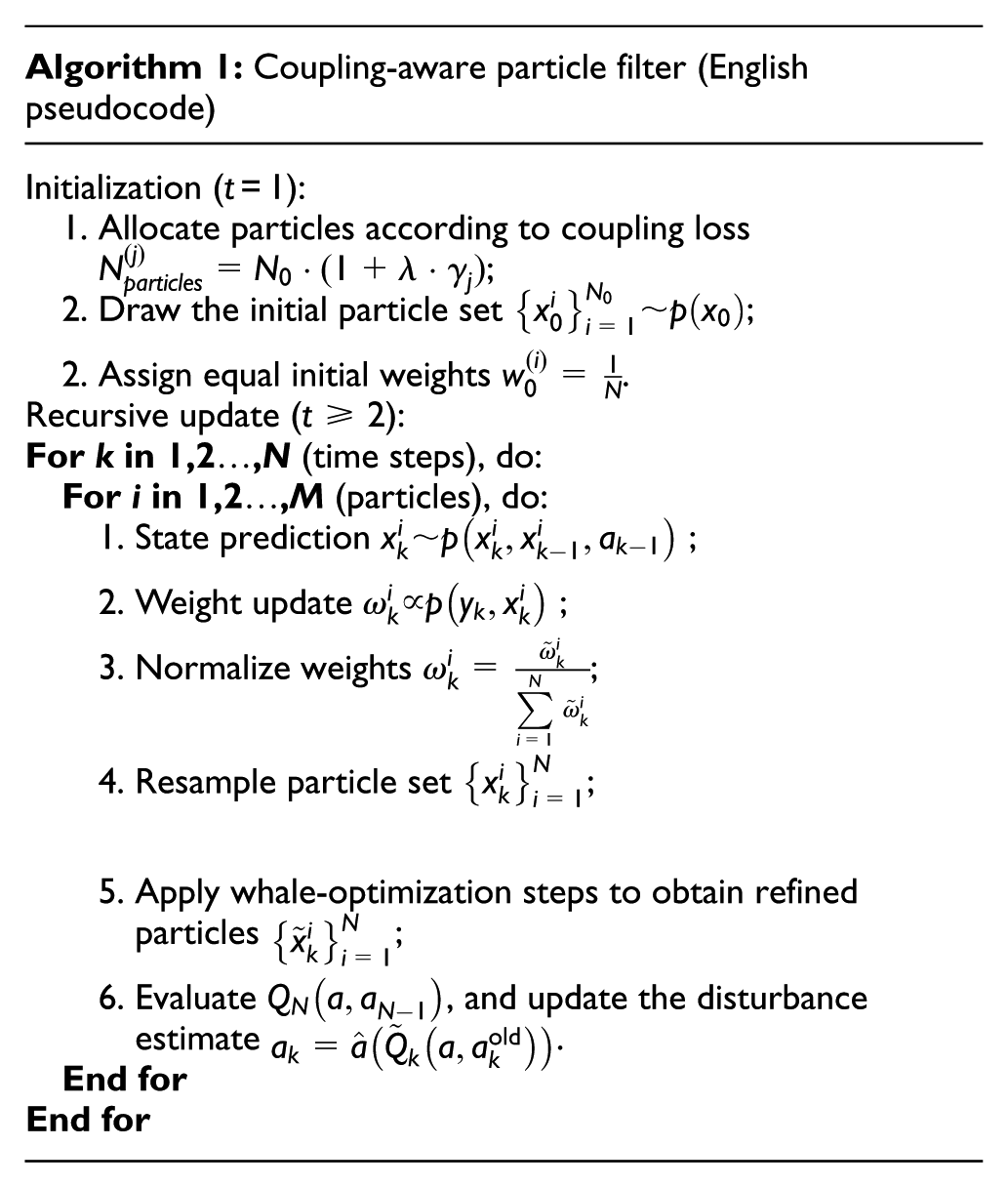
To enhance the robustness of particle filtering in state estimation for structurally complex systems, a coupling-aware particle-allocation strategy is embedded in the proposed filter. Concretely, each hardware component is assigned a structural-coupling index
Unlike conventional schemes that assign an equal number of particles to every state dimension, the present method allocates the total particle budget

where
Below is the pseudocode for the coupling-aware particle filter enhanced by the Whale-Optimization Algorithm (WOA).
Case study
Background
As a core component of large-scale power systems, a steam turbine integrates multiple functional subsystems and critical hardware elements to convert high-temperature, high-pressure steam into mechanical power with high efficiency. In practical service, the turbine is responsible not only for primary power output but also for tasks such as energy-efficiency regulation, thermal-parameter coordination, and safety control under diverse operating conditions, resulting in a tightly coupled structural and control logic.
This tight functional–structural coupling directly impacts both the reliability of the system and the accuracy of health monitoring. Cooperative operation among functional modules imposes coupled loads on shared hardware resources—such as the rotor, blades, and seals—such that the performance state of each key component is mutually influenced across different functional stages. This is a typical manifestation of function–performance coupling, where state estimation errors may accumulate if such interactions are ignored.
Moreover, the turbine routinely experiences sharp temperature swings, pressure fluctuations, and frequent start–stop cycles, which accelerate fatigue degradation and performance deterioration. In this context, developing a health monitoring framework with explicit coupling awareness is essential—not only to enhance early-fault detection and degradation tracking, but also to ensure the long-term reliability and safe operation of high-value industrial assets.
Quantitative analysis of function–performance coupling effects in a steam turbine
Focusing on a typical steam turbine system, this study selects three representative subsystems—namely, the turbine body, the water supply system, and the lubrication system—for functional and structural analysis, aiming to model the functional–physical coupling relationships and identify potential failure mechanisms. The analysis results are shown in Table 2.
Functional and structural analysis of a steam turbine system.

Based on the functional and structural decomposition of the steam turbine system, the turbine body is responsible for converting steam thermal energy into mechanical power. The water supply system handles water drainage, overflow prevention, and blade protection. The lubrication system enables lubrication, cooling, and cleaning functions.
The turbine body includes components such as the rotor, guide vane, thrust bearing, shaft, and exhaust cylinder. The water supply system consists of the manual drain valve and gas regulating valve. The lubrication system includes the main oil tank, oil pump, oil cooler, and oil filter. Based on this decomposition, each functional unit fi is defined for the three subsystems. The interactions and dependencies between these units are then analyzed from the six FRAM functional aspects—Input (I), Output (O), Precondition (P), Resource (R), Time (T), and Control (C). The results are detailed in Table 3.
Partial characterization of coupling units in a steam turbine system (f1–f5).

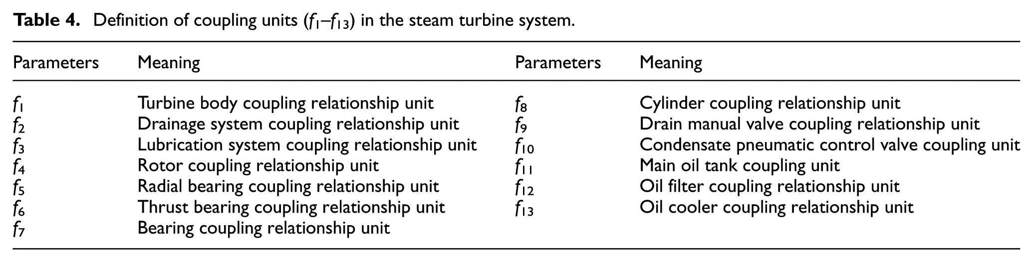
A complete definition of all coupling units (
Definition of coupling units (f1–f13) in the steam turbine system.
Based on the identification and characterization of coupling units, a Functional Resonance Analysis Method (FRAM) model is constructed by considering the upstream and downstream interactions among these units. This model captures the potential coupling relationships between functional and physical elements, thereby establishing the mapping between system functionality and hardware performance. The resulting coupling structure is illustrated in Figure 7.

Coupling model between system functions and hardware performance.
During system operation, the coupling units are quantitatively characterized from both temporal and accuracy perspectives, taking into account factors such as hardware performance degradation and functional stability. An analytic hierarchy process (AHP) is employed to adjust the discrete probabilities of changes in each coupling unit across these two dimensions.
Considering that hardware structures tend to degrade over time, leading to declining performance, the temporal variation of each coupling unit is evaluated based on four discrete condition states: intact, tolerable, affected, and failed. The resulting state transition probabilities are shown in Table 5.
Variability of coupling units.

By applying equation (4), the calculated variability values of the coupling units are obtained, as presented in Table 6. It can be observed that coupling units f4 and f11 exhibit relatively high variability, indicating that the rotor and oil tank are more prone to hardware performance changes. These components should be closely monitored, as they are more likely to cause functional disruptions even under normal system operation.
Coupling loss degree of coupling units.

Steam turbine rotor life-margin monitoring
This study focuses on the turbine rotor module of the system and investigates its fatigue-degradation mechanism under function–coupling conditions. During repeated start-up and shut-down cycles, the rotor is subjected to cyclic internal pressure and mechanical loads. Under real operating conditions, the rotor and connecting elements experience alternating tensile stresses, stress concentrations, and uncertain load paths, all of which accelerate fatigue-crack initiation and propagation. As a result, the rotor becomes one of the weakest links in overall system reliability, and its degradation poses a critical challenge for accurate health monitoring in complex, coupled environments.
To address the complexity of actual structural components and ensure experimental controllability, a compact tension (CT) specimen, designed according to the GB-T 6398-2017 standard for metal materials fatigue testing, is used as a representative structural element for fatigue modeling and validation. This specimen design is based on the fatigue crack propagation methodology outlined in the standard, ensuring that the crack growth behavior is accurately simulated under coupling disturbances.
The key dimensions of the CT specimen include: specimen thickness: 4 mm; specimen width: 50 mm; central crack length: 8 mm; distance between crack and edge: 32 mm.
This standardized design allows for precise control of crack propagation mechanics, making it an effective analog for studying fatigue behavior in more complex structural components such as turbine rotors. The stress intensity factor for crack growth is calculated using the following equation, which also follows the calculation methodology prescribed in the GB-T 6398-2017 standard:

The fatigue-crack growth behavior of metallic components is commonly characterized by the Paris law, which relates the fatigue-crack growth rate (FCGR) to the stress-intensity-factor range. Given its simplicity and wide empirical validation, the Paris equation is adopted in the present experiment as the governing model for monitoring crack-length evolution during fatigue testing.

To characterize the crack-length evolution of the turbine cylinder under cyclic loading, the Paris law is embedded in a discrete-time state-space form. Let

Because crack-length evolution exhibits three essential properties—(1) non-negativity, (2) monotonic non-decrease, and (3) statistical unbiasedness—the process noise is typically introduced in a multiplicative form,
Because the Paris constant
The instantaneous performance margin is defined as the difference between the crack-length threshold

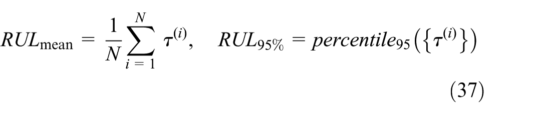
Remaining useful life (RUL) is predicted by forward-propagating each posterior particle
For the ith particle the crack length after τ additional load cycles is:

The hitting time
Results and discussion
To emulate distinct operating conditions, six turbine-cylinder specimens were tested under three equivalent mean-stress ranges:

With the adaptive-allocation rule

particles for state estimation. The same procedure is applied to all remaining units, ensuring that components with stronger coupling receive a denser particle representation. Fatigue-crack growth is then monitored using the proposed WOA-enhanced EM–PF algorithm; the resulting crack-length trajectories are shown in Figure 8.

Estimated crack length and 95% prediction interval. (a) Specimen 1. (b) Specimen 2. (c) Specimen 3. (d) Specimen 4. (e) Specimen 5. (f) Specimen 6.
A comparison was made between the estimated crack length and the actual experimental measurements. Due to uneven sampling in the early stage of fatigue testing, the initial phase showed sparse data points, leading to relatively high deviations and wider prediction intervals. However, as the sampling frequency increased in the later stages of fatigue testing, the prediction accuracy improved accordingly.
During the iterative estimation process, the error between the predicted crack length and the observed value remained below 5%, validating the accuracy of the proposed DBN-based framework. This confirms the practical applicability of the method for structural safety assessment and predictive maintenance.
To evaluate the effectiveness of the improved algorithm framework, the accuracy of remaining useful life (RUL) prediction was compared across three different algorithms. The absolute error of RUL prediction was selected as the evaluation metric, and the results are shown in Figure 9.

Estimated crack length and 95% prediction interval. (a) Specimen 1. (b) Specimen 2. (c) Specimen 3. (d) Specimen 4. (e) Specimen 5. (f) Specimen 6.
According to the comparison, the improved particle filter algorithm incorporating Metropolis–Hastings (M–H) resampling exhibits superior prediction performance in practical applications. It achieves higher accuracy than the standard particle filter. However, the performance gap between the coupling-aware method and the variant considering unknown process inputs is relatively small. To further clarify the performance difference, the average absolute RUL prediction error of the three methods was calculated, and the results are presented in Table 7.
Comparison of absolute RUL prediction errors using different methods.

The bolded text indicates that the proposed method demonstrates optimal performance in computational results.
The case study demonstrates the applicability and effectiveness of the proposed method through two levels of analysis. At the system level, a coupling network of a steam turbine was constructed to support reliable state estimation and enhance health monitoring. At the component level, a fatigue degradation model driven by coupling disturbances was established using compact tension specimen tests. Results show that the proposed method achieves high accuracy in crack monitoring and RUL prediction, especially under the improved particle filtering framework, highlighting its potential for reliability-oriented engineering applications.
Conclusions
This study presents an integrated framework that addresses state-evolution uncertainty caused by function–performance coupling in complex manufacturing systems. Coupling relationships are first identified from functional requirements and structural dependencies, quantified via a loss-degree metric, and embedded as hidden variables in a discrete state-space model. The associated disturbances are then estimated online using an EM-enhanced Bayesian procedure, while a coupling-driven particle allocation strategy dynamically adjusts the particle count based on coupling severity. Applied to a steam turbine case and a cylinder fatigue experiment, the method improves health monitoring accuracy and reduces RUL prediction error compared to standard filters, demonstrating strong potential for reliability-oriented management of highly coupled equipment.
In future work we will extend the framework to systems that undergo task shifts or structural re-configurations, enabling on-line re-identification of coupling paths and rapid model adaptation; integrate micro-scale fatigue mechanisms with the macro-level state-space formulation to build a true multi-scale degradation-prediction scheme.
Footnotes
Handling Editor: Shun-Peng Zhu
Funding
The authors received no financial support for the research, authorship, and/or publication of this article.
Declaration of conflicting interests
The authors declared no potential conflicts of interest with respect to the research, authorship, and/or publication of this article.