
Abstract
Flexible shafts, exhibiting excellent tensile and torsional transmission characteristics, serve as an ideal power transmission medium for the design of flexible continuum robots. This study introduces a novel rigid-flexible hybrid robotic mechanism employing six flexible shaft actuators to achieve seven degrees of freedom (DOFs). The design integrates a dual-segment flexible body with a single-segment rigid body. A comprehensive kinematic model was derived to describe the hybrid structure’s motion. Concurrently, a static model was developed, incorporating driving forces, external loads, gravitational effects, and the combined elastic forces from the flexible driving shafts and spinal rods. Based on this static model, 182 combinations of flexible shaft pulling forces and distal loads were applied to control the robot’s posture. Experimental results indicated that the maximum positional errors for the single- and dual-segment configurations were 2.67% and 5.97% of the manipulator length, respectively. The maximum root mean square error for spatial configuration repeatability is 0.4 and 5.1 mm for single- and dual-segment flexible robots, respectively. The kinematic and static models developed in this research accurately predict the spatial configuration of the flexible continuum robot, which features an integrated elastic arrangement of driving shafts and spinal rods, thereby facilitating rapid deployment in similar flexible robotic systems.
Keywords
Introduction
Minimally invasive surgery (MIS) is widely utilized in surgical treatments due to its advantages of smaller incisions, less blood loss, and shorter hospital stays. Surgical robots, leveraging robotic technology, not only retain the benefits of traditional MIS but also enable more precise surgical movements, reduce the workload on surgeons, and minimize postoperative complications for patients. 1 Minimally invasive surgical techniques guided by endoscopic or laparoscopic imaging primarily encompass transoral surgery, thoracoscopic and laparoscopic surgery, as well as transvaginal, transurethral, and transrectal procedures. These techniques effectively meet the requirements for various surgical procedures in thoracic surgery, 2 general surgery,3,4 urological surgery, 5 and gynecological surgery.6,7
In the aforementioned surgical methods, there is typically a certain distance from the patient’s body surface to the surgical site. Additionally, the posture of the surgical instrument as it enters the body varies depending on the surgical site, which imposes stringent requirements on the capability to flexibility and dexterity. Current surgical robots, particularly those based on continuum structures, still face significant challenges. A primary limitation lies in their actuation mechanisms. Many rely on traditional tendon/cable drives, which can only transmit tensile forces, 8 making it difficult to actuate complex distal mechanisms requiring torque, such as rotational wrists or graspers.
To overcome these limitations, rigid-flexible hybrid mechanisms have garnered increasing research attention. These designs seek to synergize the adaptability of flexible segments with the load-bearing capacity and operational precision of rigid segments. However, a review of prior studies reveals a common challenge in achieving a truly integrated and compact system. For instance, Li et al. 9 explored hybrid structures by combining novel composite materials with rigid elements, yet such approaches are limited in output force and control accuracy. Paternò et al. 10 integrated flexible actuators within a rigid frame to balance compliance and output force, but their dependence on external pneumatic power sources and complex fabrication processes restricts broader adoption. Furthermore, Wu et al. 11 integrated a parallel mechanism with a tendon-driven continuum segment to balance positioning precision and posture adaptability; however, the auxiliary parallel mechanism increases the complexity and bulk of the actuation system, and the distal flexible manipulator, limited by tendon-driven actuation, often possesses insufficient degrees of freedom for versatile tasks. In summary, while research on rigid-flexible hybrid mechanisms has achieved notable progress, a common characteristic in these designs is that the actuation systems for the rigid and flexible parts remain largely separate and decoupled, leading to increased structural complexity. This study proposes a novel flexible robot driven by the tensile-torsional synergistic actuation of flexible shafts. Unlike traditional tendons, this design ingeniously leverages the dual functionality of the flexible shaft: serving as a medium for tensile-bending actuation of the flexible segments and concurrently transmitting torque to the distal rigid joint. This approach simplifies the robot’s drive system, obviates the need for auxiliary drive chains for the rigid joint, and reduces structural complexity while enhancing the robot’s overall dexterity.
An accurate mathematical model is essential to better design, analyze, and control flexible robots driven by flexible shaft pull-twist systems. 12 Given the lightweight design of this robot and its application in slow-moving conditions, static and kinematic studies are prioritized over dynamics analysis. 13 The kinematic and static modeling methods for continuum mechanisms primarily include the constant curvature model, 14 the piecewise constant curvature model,15–17 the Cosserat rod model, 18 and the pseudo-rigid body model.19,20 Among these, the piecewise constant curvature method is favored for its high computational efficiency, convenient modeling, and broad applicability, has been successfully implemented in numerous kinematic and static models.21,22 For instance, a real-time modeling and verification scheme for continuum robots using piecewise constant curvature kinematics was introduced in Barrientos-Diez et al., 23 achieving real-time control and operation of continuum robots in various scenarios. Similarly, model-based feedforward position control method was proposed in Falkenhahn et al., 24 where the continuum robot was precisely controlled using the piecewise constant curvature model, demonstrating its efficiency and accuracy in applications. Despite the widespread success and proven utility of the piecewise constant curvature method, its accuracy often relies on a key simplifying assumption: the actuation elements (e.g. cables or tendons) are treated as ideal, one-dimensional strings that contribute to the robot’s motion only through tension, while possessing no intrinsic bending stiffness themselves. In these models, the robot’s overall bending resistance is attributed solely to the central elastic backbone. This simplification, while computationally convenient, overlooks the contribution of actuation elements with non-negligible cross-sections (such as the flexible shafts used in this study) to the overall structural rigidity. This can lead to inaccuracies in predicting the robot’s shape, especially under significant external loads.
To accurately describe the shape or motion of flexible robots driven by the coordinated pull-twist of flexible shafts, this paper proposes a statics model with comprehensive consideration of various factors, including the driving forces on the flexible shafts, the interaction forces at the manipulator’s end-effector, the gravitational forces and moments of the spacer disks and elastic backbones, as well as the elastic forces and moments. Powder metallurgy oil-impregnated bearings are used to reduce the frictional force when the flexible shafts pass through the spacer disks. This unique design eliminates influence of friction in the statics model. Compared to existing research, the main contributions of this paper are as follows:
This study presents a multi-segment rigid-flexible hybrid dexterous robot structure driven by a novel “pull-twist” synergistic actuation mechanism. Unlike conventional designs where actuation for flexible and rigid parts are decoupled, our approach ingeniously uses the dual functionality of flexible shafts: the “pulling” motion actuates the bending of the continuum segments, while the “twisting” motion of the same shafts concurrently drives the distal multi-DOF rigid joint. This highly integrated design, proven feasible by a physical prototype, obviates the need for separate drive systems, significantly reducing mechanical complexity and size.
For the first time, this study incorporates the elastic properties of the driving flexible shafts into the static model of a rigid-flexible hybrid flexible robot. A comprehensive static model of the flexible body is proposed, taking into account multiple factors, and a kinematic model of the robot is established. The static model of the integrated elastomer configuration, which includes the elastic flexible shafts and elastic spinal rods, more accurately describes the spatial pose and shape of the flexible robot. This model addresses the deformation behavior of the robot under different external loads and drive combinations and systematically evaluates the impact of drive parameters on the shape and stability of the flexible robot.
The constructed pose description model and static model of the rigid-flexible hybrid robot demonstrate good versatility. They can be quickly adapted for the deployment of static models for flexible robots with various power transmission media, such as elastic flexible shaft drive-elastic spinal support rod and inelastic cable drive-elastic spinal support rod. Additionally, the number of spacer disks in the flexible joints, the number of routing holes, the number of flexible joints, and the degree of freedom configuration of the rigid joints can all be freely defined.
The structure of the paper is as follows: the flexible robot system driven by the coordinated pull-twist of the flexible shafts is described first. Next, the kinematic model of the rigid-flexible hybrid manipulator and the static model are constructed, considering driving force, external environmental forces, gravitational forces, and elastic forces, including the flexible shaft’s elastic properties. Then, the experimental setup and validation work are detailed, followed by a discussion on error analysis. Finally, the main conclusions and future extensions of this work are presented.
System description
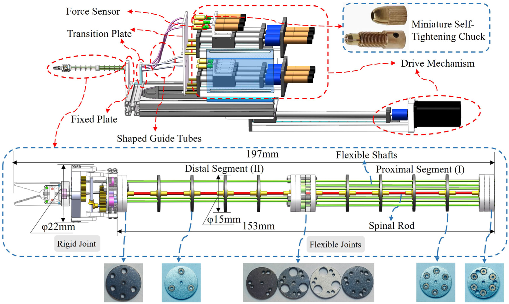
The flexible robot system, incorporating the combined elastomer of the drive shafts and spinal rods, is illustrated in Figure 1, primarily consists of a drive module, shaped guide tubes, a rigid-flexible hybrid manipulator, a transition plate, and force sensors. The rigid-flexible hybrid manipulator is composed of a 4-DOF dual segment flexible joint and a 3-DOF rigid joint, powered by 9 brushless DC motors (CBL2040-2416F, Techrobots, China). Additionally, a linear joint is developed to actuate the translational reciprocating motion of the entire rigid-flexible hybrid manipulator. Miniature self-tightening chucks are used to secure the flexible shafts to the motor output shafts. The flexible shaft originates from the motor output shaft, passes through the shaped guiding tube channel, the hollow channel of the transition plate, and the manipulator’s mounting plate, ultimately reaching rigid-flexible hybrid manipulator base.
Flexible robot system with elastic configuration of flexible shafts and spinal rods.
The rigid-flexible hybrid manipulator comprises two flexible joints and one rigid joint. Each flexible joint consists of multiple spacer disks, an elastic backbone, and several flexible shafts. The spacer disks are used to guide the flexible shafts along the motion path. The spacer disks and flexible shafts are fabricated from 304 stainless steel, while the elastic backbones are constructed using a NiTi alloy. A series of modular spacer disks, with identical in thickness but different in aperture design, are designed and manufactured. These disks allow for quick assembly and disassembly through different stacking schemes, facilitating flexible changes in the manipulator’s shape configuration. Friction between the flexible shaft and the spacer disk is significantly reduced by embedding a powder metallurgy oil-impregnated bearing within the wiring aperture of the spacer disk. When using the constant curvature method to construct the static model of a flexible continuum robot, in order to reduce the posture error of the static model, the preferred ratio of distance between two spacer disks to the distance from the wiring aperture to the elastic backbone should be 0.4. 25 Given that the distance from the wiring aperture to the elastic backbone is 5 mm in this manipulator, the distance between two spacer disks is determined to be 12.5 mm.
Modeling
Kinematic analysis
In this section, the kinematic analysis of the rigid-flexible hybrid robot, is performed based on the combined use of the piecewise constant curvature method and Denavit–Hartenberg (D-H) parameters method. The notation used in this paper is provided in Table 1. The elastic backbone is assumed to be composed of a series of mutually tangent segments, each of which is approximated as an arc with constant curvature. Supposed the torsion of the elastic backbone is negligible, therefore, only the deformation of the elastic backbone in the plane will be considered. The unique rigid-flexible hybrid robot consists of a dual-segment flexible joint and a rigid joint, driven by flexible shafts through pull-twist coaxial coordination. The wiring coordinates of the flexible shafts passing through the spacer disks are illustrated in Figure 2(a), where paths 1, 2, and 3 represent the wiring paths of the distal segment, and paths 4, 5, and 6 represent the wiring paths of the proximal segment. Furthermore, the numbers of these wiring paths are consistent with the motor identifiers, which will be mentioned in the following sections. The angular positions of these wiring coordinates in the manipulator coordinate system are defined in equation (1) as follows:

Nomenclature.


Schematic diagram of the wiring coordinates on the spacer disks: (a) definition of wiring coordinates on the spacer disks and (b) spacer disks with powder metallurgy oil-impregnated bearings for the proximal and distal segments.
The nomenclature of the coordinate system for the flexible joint is illustrated in Figure 3. And this naming convention is also applicable to each locally tangent segment. The elastic backbone is defined by
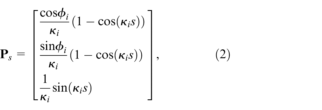
where

where

Nomenclature of the coordinate system in flexible joints.
The coordinates of arbitrary point at the

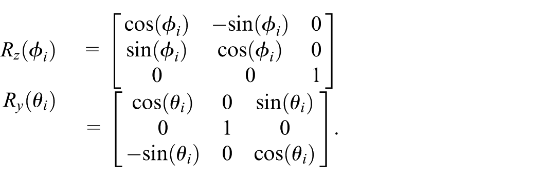
where matrices
Considering the torsion of the elastic backbone, the variable

Thus, we can calculate the pose information of any point on the elastic backbone in the two-segment flexible joint, including the pose information of the 10 spacer disks. To ensure the continuity of the position and orientation at the rigid-flexible coupling, the continuity condition is defined as:

where
To better describe the pose of the rigid joint attached to the second segment of the flexible joint, the coordinate system at the distal of the flexible joint is defined as
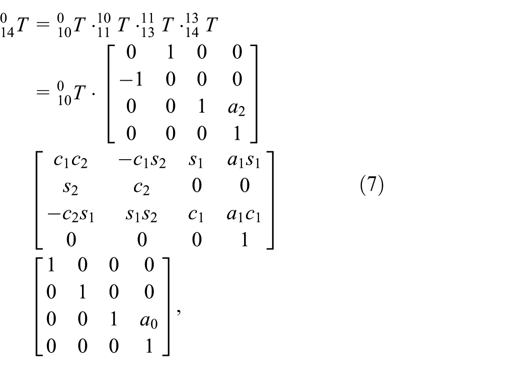
where
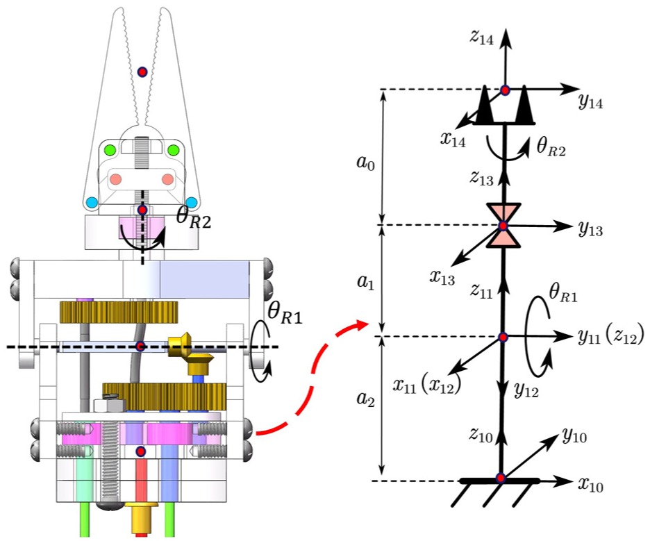
Naming convention and coordinate system definition for the rigid joint.
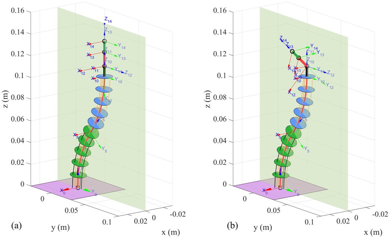
Nomenclature of the manipulator coordinate system: (a)
Static analysis
In this section, a static analysis is conducted on the rigid-flexible hybrid robot driven by the flexible shafts through pull-twist coaxial coordination, as shown in Figure 6. The flexible continuum robot comprises a series of identical adjacent units. For instance, the

Schematic diagram of the static analysis of the manipulator, where the flexible shafts between each two adjacent spacer disks are in a straight-line configuration.
Tensile force on the flexible shafts
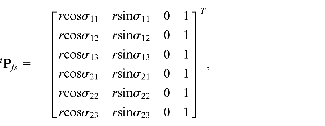
The position matrix of the wiring channels in the

where
where

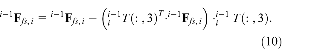
where
Since powder metallurgy oil-impregnated bearings are embedded in the wiring channels of the spacer disks, the friction between the flexible shafts and the spacer disks can be ignored by means of the fine lubrication characteristics of the bearings. Thus, the force perpendicular to the spacer disk is zero. Furthermore, the orthogonal forces exerted by the flexible shafts on the spacer disks are eliminated when
The torques generated by the forces exerted by the flexible shafts on the spacer disks can be described as follows

Interaction force with the external environment
The interaction forces with the external environment, representing as the force vectors applied to the end of the manipulator in the base coordinate system, can be described as follows:

where

where
Gravitational force and moment
The gravitational forces primarily include the both gravity of the spacer disks and the elastic backbones. In this study, the direction of gravity is aligned with the negative y-axis. Therefore, the gravitational forces of the spacer disks in the

where
For the elastic backbones, the centroid position of the

where

Thus, the forces and moments acting on the

where
Elastic force and moment
The bending moment along the axial direction of the elastic backbone is simplified as a linear relationship proportional to its curvature by using piecewise constant curvature method. 27 Supposed that both the elastic backbone and the flexible shafts are inextensible, thereby only deformations caused by bending movement are considered. In this study, the flexible shafts are uniformly distributed on the spacer disks with a circumference of certain radius. Therefore, the equivalent moment of inertia of the flexible shaft in the robot can be expressed as:

where
where

Suppose that the flexible robot rotates around the
where
The comprehensive static equilibrium equation of the flexible continuum robot can be expressed as follows:

By setting
The solutions for

where
Experimental evaluation
Experimental setup
A robot prototype is constructed to evaluate the static performance and shape prediction accuracy of the proposed flexible continuum robot driven by flexible shafts, which is shown in Figure 7. The pulling action of the flexible shafts is used to adjust the spatial posture of the two flexible joints, while the twisting motion of flexible shafts 1, 2, and 3 controls the pitch, rotation, and opening-closing functions of the rigid joint. Brushless DC motors (CBL2040-2416F, Techrobots, China) are used to provide the driving force for the flexible shafts. Tension-compression force sensors (RDF-TM10, Ryder, China), which are fixed to the motor’s output shaft, are used to measure the tension on the flexible shafts, while providing a comprehensive accuracy of 0.1% of full scale. An optical dynamic capture system is used to sense the postural information of the flexible continuum robot through identifying the position of the optical markers, which are placed at spacer disks along the elastic backbone. The optical dynamic capture system comprises four motion capture cameras (1280 × 1024 resolution, MARS1.3H, Nokov, China), achieving a maximum frequency of 240 FPS, and a positional accuracy of

Experimental platform and functional demonstration of the rigid-flexible hybrid robot: (a) the overall experimental setup, comprising the drive mechanism, optical motion capture system, and the manipulator and (b) functional demonstration of the robot, showing the rigid joint performing pitch, rotation, and opening-closing motions, and the flexible joints performing multi-segment bending.
The materials and geometric parameters of the flexible robot prototype.

Shape control validation
Shape perception experiment of single-segment flexible robot
A single-segment flexible robot consists of five spacer disks, one elastic backbone, and three flexible shafts. Reflective markers with a diameter of 8 mm are placed at the right above of the placer disks, and the three-dimension positions of the reflective markers are collected by using the optical dynamic capture system. At the initial condition, the traction on the flexible shafts is zero, while applying no external load at the distal of the flexible robot. The three-dimension positions of the reflective markers obtained from the optical dynamic capture system are shown in Figure 8. The black dots indicate the experimental data of the center position of the spacer disks, while the red solid line represents the simulation results of the elastic backbone under the static model. The Euclidean distance between the simulation data and the experimental data at the reflective marker position is calculated, therefore, the maximum Euclidean distance among these five spacer disks is 0.9 mm, accounting for 1.33 mm of the length of the flexible robot, and the average Euclidean distance among these five spacer disks is 0.6 mm, equivalent to 0.89 mm of the length of the flexible robot, indicating that the static model of the flexible robot has good tracking accuracy when the flexible robot is at its initial state.

Zero driving force and external load on the single-segment flexible robot.
The shape of the flexible robot based on static model under the traction by a single flexible shaft is analyzed. As shown in Figure 2, the

Shape data of the single-segment flexible robot under different tractions of the

Shape data of the single-segment flexible robot under different tractions of the

Shape error data of the single-segment flexible robot under different tractions of the
The 3D shape of the flexible robot based on static model under the traction by two flexible shafts is analyzed. The
3D shape data of the single-segment flexible robot under tractions of two flexible shafts: (a) three-dimensional spatial shape data and (b) bending state of the flexible robot under configurations 4, 5 (11, 8.65 N).
External load testing for the single-segment flexible robot
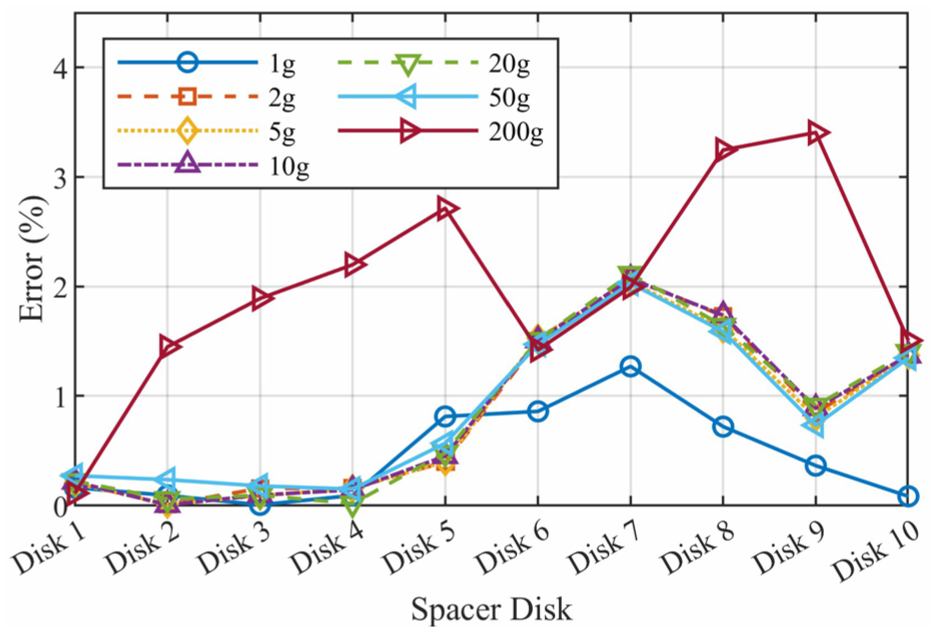
In this section, the shape of the flexible continuum robot under external loads is analyzed. Different standard weights (1, 2, 5, 10, 20, 50, and 200 g) are hung at the end of the single-segment flexible robot, while the direction of gravity of the weight is consistent with the −y axial direction. Experimental and simulation results of the flexible robot’s shape under different loads are presented in Figure 13, where the red solid line represents simulation results of the elastic backbone, and black dots indicate experimental results at the corresponding spacer disks. The ratio of the maximum displacement error to robot length under different loads are shown in Figure 14. The experimental results demonstrate that the maximum error ratio is 3.56% when the external load is less than 50 g. The maximum error ratio increases to 6.81% when the external load is 200 g.

Shape data of the single-segment flexible robot under different loads.

Evolution of model accuracy with different external loads at different spacer disks.
Shape perception experiment of dual-segment flexible robot
In this section, the performance of the proposed static model is further investigated by using a dual-segment flexible continuum robot. The proximal segment of the flexible robot comprises four identical spacer disks with six routing paths, while the distal segment consists of four identical spacer disks with three routing paths. Shape data of the dual-segment flexible continuum robot are obtained by using 11 reflective markers located at the spacer disks along the axial direction of the robot’s elastic backbone. The overall length of the dual-segment flexible continuum robot is 140.75 mm. In the initial condition, the traction of each flexible shaft is set as 0, and no external load is applied on the flexible robot. The experimental and simulation results are shown in Figure 15. The ratio of the average and maximum displacement errors to robot length are 1.49% and 2.42%, respectively.

Driving force and external load are both 0 on the dual-segment flexible robot.
The planar shape analysis of the dual-segment flexible continuum robot under the pulling action of two flexible shafts are conducted on different traction configurations. The six traction configurations are as follows: 2 and 5 (6.96, 15.22 N), 2 and 5 (7.56, 15.07 N), 2 and 5 (9.96, 17 N), 3 and 4 (8.37, 15.97 N), 3 and 4 (8.55, 14.88 N), and 3 and 4 (7.82, 10.11 N). When a set tensile force is applied to the two specified flexible shafts, a pretension force of 2 N will be applied to other flexible shafts. The flexible shaft needs to pass through a shaped conduit from the motor output to the base of the flexible robot, therefore, the traction at the base of the flexible robot and the traction at the output end of the corresponding motor need to be converted. For example, under the configuration of 2 and 5 (6.96, 15.22 N), the traction on the corresponding motor output end is 2 and 5 (10, 50 N), and the real-time force data at the motor output end are shown in Figure 16. The shapes of the dual-segment flexible robot under traction by two flexible shafts 2, 5 and 3, 4 are presented in Figures 17 and 18, respectively. The ratios of the average and maximum displacement errors to robot length under different traction configurations by combination of the
Real-time force data at flexible shafts 2 and 5 (7.61, 15.73 N).

In-plane shape data of the dual-segment flexible robot driven by flexible shafts 2 and 5.

In-plane shape data of the dual-segment flexible robot driven by flexible shafts 3 and 4.
The 3D shape of the dual-segment flexible continuum robot under the traction of three flexible shafts is analyzed. The detailed combination of three flexible shafts is shown in Figure 19. The blue solid line with circle markers represents experimental data, and the red solid line represents simulation data for the elastic backbone. The ratios of the average and maximum displacement errors to robot length under different traction configurations by the three flexible shafts are 1.78% and 5.97%, respectively.

The shape error data of a dual-segment flexible robot under out-of-plane tension tests on three flexible shafts: (a) three-dimensional spatial shape data and (b) bending states of the robotic arm under configurations 1, 2, and 5 (5.21, 8.04, 12.71 N).
External load testing for the dual-segment flexible robot
The load capacity of the dual-segment flexible robot is verified when the
Evolution of model accuracy with different spacer disks under varying external loads.
Positioning repeatability experiments
To assess the positioning repeatability of the proposed flexible continuum robot, traction configurations by flexible shafts are conducted for robot’s shape planning. In this experiment, the flexible shaft as the transmission medium for tensile force includes two situations: the first situation is that the flexible shafts used as driving source come from the same flexible segment, and the second situation is that the flexible shafts used as driving source come from the two different flexible segments. In the first situation, 15 traction configurations including 4(2.71), 4(5.3), 4(7.54), 4(10.42), 4(12.4), 6(2.75), 6(5.42), 6(7.99), 6(10.37), 6(13.61), 4, 5(3.39, 3.51), 4, 5(12.28, 5.9), 4, 5(11, 8.65), 5, 6(5.96, 12.2), and 5, 6(8.79, 10.33 N) are implemented. In the second situation, 12 traction configurations including 2, 5(6.96, 15.22), 2, 5(7.56, 15.07), 2, 5(9.96, 17), 3, 4(8.37, 15.97), 3, 4(8.55, 14.88), 3, 4(7.82, 10.11), 1, 2, 5(2.22, 8.17, 14.24), 1, 2, 5(5.21, 8.04, 12.71), 2, 3, 5(8.53, 3.18, 13.22), 2, 3, 5(7.62, 3.9, 12.2), 2, 5, 6(3.11, 10.55, 3.56), and 2, 5, 6(2.46, 8.63, 4.57 N) are implemented. All the traction configurations are repeated implemented five times, and the root mean square error (RMSE) for each traction configuration is calculated, as shown in equation (23).

where

Repeatability experiments of single-segment flexible robot.

Repeatability experiments of dual-segment flexible robot.
Discussion
In this study, a flexible continuum robot driven by flexible shafts is constructed and shape perception of the flexible continuum robot based on static model is analyzed. Tensile force on the flexible shafts, interaction force with external environment, gravitational force and moment, elastic force generated by spinal rods and flexible shafts, are comprehensive considered in the static analysis. The shape perception of flexible continuum robot under traction configurations by flexible shafts are performed, it shows that the simulation results of the pose and shape of the flexible continuum robot based on the static model have good consistency with the experimental results. The features of the flexible continuum robot based on the static model are summarized as follows.
Pull-twist coaxial collaboration actuation by flexible shafts
The proposed robot comprises of a rigid-flexible hybrid robotic mechanism. The rigid-flexible hybrid robotic mechanism consists of a 4-DoF dual-segment flexible continuum part and a 3-DoF rigid part, while, the distal of the flexible continuum part and the rigid part share the same mechanism. Six flexible shafts enter the robot’s body from the root, with three shafts terminating at the end of the first segment flexible joint, and the other three flexible shafts passing through the first segment flexible joint, terminating at the end of the second segment flexible joint, and connected to the driving rod of the rigid joint. The pulling effect of the flexible shaft can control the universal bending motion of the flexible joints, and the twist of the flexible shafts connected to the rigid joint can control the rigid joint to achieve the functions of forceps’s pitch, rotation, and opening-closing. This new approach can decrease the number of the mechanical components in the robot body for dexterous structure, and reduce the mechanical complexity of robot body.
Static model under comprehensive consideration of elastic components
The shape accuracy of the flexible continuum robot is related to the pull force of the actuator, external interaction force and its moment caused by external load, gravity and moment of each robot component, and the elastic force and its moment generated from bending movement of the elastic components. Compared with rope pulled flexible robot, the shape accuracy of the developed flexible robot driven by flexible shafts is not only affected by the traction and moment generated by the pulling effect of the flexible shaft, but also by the additional elastic force and moment generated by the elastic bending deformation of the flexible shaft. In this study, the flexible shafts are uniformly distributed on the spacer disks with a circumference of certain radius, while the elastic spinal rod is located at the center of the spacer disks. Therefore, the equivalent bending moment of the elastic comprehensive combination of the flexible shafts and the spinal rods can be calculated using parallel axis theorem. The theoretical computation was introduced in Elastic Force and Moment, and the shape perception of the flexible continuum robot was presented in Section Motion Performance Validation. The experimental results are consistent with the simulation results based on the theoretical analysis.
To model static shape estimation, we employed the piecewise constant curvature approach due to its high computational efficiency and suitability for the complex force interactions in our robot design. However, we acknowledge the limitations of PCC in capturing variable curvature characteristics under certain conditions. In high external load scenarios (e.g. 200 g), the maximum error ratio reaches 6.81% for single-segment robots and 3.41% for dual-segment robots. For non-planar deformations, such as dual-segment three-axis traction configurations, the maximum error ratio increases to 5.97%. The underlying reason for this discrepancy lies in the inherent limitations of the piecewise constant curvature model when dealing with non-uniform, large deformations. When a significant, concentrated load is applied at the distal end, the robot’s physical shape is no longer a smooth, constant-curvature arc. Instead, it exhibits a highly non-uniform bending profile, characterized by a sharp, high-curvature bend near the load, while the proximal section remains less deformed. The piecewise constant curvature model approximates this entire non-uniform segment with a single curvature value, and this averaging process leads to a geometric deviation from the true shape, resulting in the observed positional errors. To mitigate this, we optimized the segmentation (using 5 spacer disks for single-segment robots and 10 for dual-segment robots) to enhance accuracy within acceptable bounds. In future work, we plan to explore variable curvature models, such as Cosserat rod theory, to further improve shape estimation accuracy under high external loads and non-planar deformations.
In the current static analysis, only the influence of elastic force and moment generated by bending deformation under the traction of the flexible shaft on the shape accuracy of the flexible continuum robot has been considered, however, the influence of the flexible shaft caused by the torsional deformation has not been taken into account. Although the twist of the flexible shaft is intended to transmit power to the distal rigid joint of the rigid-flexible hybrid mechanism, the pull-twist coaxial collaboration will cause motion coupling on the flexible robot. Therefore, it is necessary to comprehensively consider the impact of the pull-twist coaxial collaboration of the flexible shafts in future work.
Rigid-flexible hybrid structure in the static model
The developed static model in this study takes into account the characteristics of the hybrid structure integrating the flexible and rigid joints. Based on the structural feature that the base of the rigid joint is the distal of the flexible joint, an entire kinematic model of the rigid-flexible hybrid mechanism is established, therefore, the position accuracy of the distal of the rigid-flexible hybrid robot under the used of the developed static model is guaranteed.
Conclusions
This paper presents a shape model for a novel flexible robot with elastic configuration consisting of the flexible shafts for power transmission and spinal rod for stem supporting. The entire static model is constructed under comprehensive consideration, including tensile force on the flexible shafts, interaction force with the external environment, gravitational force and moment, and the elastic force and moment in the elastic combination of the flexible shafts and spinal rods. The shape accuracy of the proposed robot under the kinematic and static models are validated through a total of 182 experiments. For single-segment flexible robot, the ratios of the average and maximum displacement errors to robot length in planar shape perception are 2.67% and 2.52%, respectively. And they become 2.22% and 1.04% when performing 3D shape perception. For dual-segment flexible robot, the corresponding ratios in planar shape perception are 1.71% and 4.69%, respectively. And they become 1.78% and 5.97% when performing 3D shape perception. Furthermore, the shape accuracy of the flexible robot with external loads were assessed, it demonstrated that the experimental results are consistent to the calculated value based on the static model when the external load is less than 200 g. The experimental results show that the flexible robot with the static model owns good shape accuracy in potential application scenarios.
In the future, the influence of the pull-twist coaxial collaboration of the flexible shafts will be considered into the static model, aiming to construct precise modeling of the rigid-flexible hybrid mechanism. Meanwhile, artificial intelligence methods, such as machine learning, will be used to establish the mapping relationship between various inputs and the robot’s shape information, including the tensile force and torsion, translational displacement, and twist angle of the flexible shafts. To deploy the improved mathematical models in real-time control systems, quantitative analysis on calculation time, robustness, and other factors will be conducted to ensure the effectiveness and responsiveness of the models in practical applications.
Footnotes
Handling Editor: Chenhui Liang
Funding
The authors disclosed receipt of the following financial support for the research, authorship, and/or publication of this article: This work was supported by Guangdong Province Basic and Applied Basic Research Fund Project (No. 2023A1515012427, 2023A1515140026), Engineering Technology Research Center for Ordinary Universities in Guangdong Province (No. 2024GCZX005), Key Fields Special Project for Ordinary Universities in Guangdong Province (No. 2024ZDZX2083), Research Foundation of Guangdong Medical Science and Technology (No. B2023109).
Declaration of conflicting interests
The authors declared no potential conflicts of interest with respect to the research, authorship, and/or publication of this article.