
Abstract
The paper investigates the effects of annular fins and different phase change material thickness (tpcm) on the thermal performance and charge/discharge times of latent heat thermal energy storage (LHTES) systems. It compares liquefaction and solidification times for both low- and high-temperature PCMs. Four cases were experimentally tested under discharge conditions with inlet water temperatures of 15°C and 25°C, and mass flow rates of 0.005 and 0.01 kg/s. During charging, inlet temperatures were maintained at 70°C and 80°C. The findings indicate that the introduction of fins greatly enhances system performance. For instance, solid fraction values rose by as much as 551.4% in systems with PCM-2 and a 30 mm tpcm. Outlet water temperature was enhanced by 40.13%, 23.49%, 27.87%, and 16.15% in the four cases. Heat transfer during discharge was enhanced by as much as 150.54% for PCM-1 and 100.4% for PCM-2. Fins also reduced charging times, decreasing from 70,000 to 66,825 s and from 67,891 to 64,877 s in systems with PCM-2. Heat transfer during charging was enhanced by up to 17.7% in systems with PCM-1. The paper identifies fins as an effective LHTES system enhancement technique.
Introduction
The clean energy transition is a critical issue that must be addressed to ensure a sustainable environment for future generations. For decades, researchers have investigated ways to generate electricity from renewable energy sources and to develop stable, reliable energy storage systems. Today, advancements in renewable energy technologies are progressing rapidly, with the share of renewable energy sources over 40% in developed countries, driven by regulations and energy policies. 1 Reliable energy storage systems are essential for achieving stable, efficient, and cost-effective energy transitions. These systems allow excess energy to be stored for use during peak-load periods or when energy generation is unavailable. Research on energy storage systems is broadly categorized into areas such as electrochemical storage, hydrogen storage, thermal energy storage (TES), and more. To increase the share of renewable energy sources, integrated systems using renewable energy technologies are required for domestic hot water production and space heating. TES is one of the most effective solutions for closing the gap between energy supply and demand and eliminating mismatches, 2 and is particularly advantageous for space heating and domestic hot water production. TES is divided into three types by their features latent heat thermal energy storage (LHTES), sensible heat thermal energy storage (SHTES), and hybrid thermal energy storage (HTES). Phase change materials (PCMs) have gained prominence in recent decades due to their high latent heat and phase change temperatures, making them well-suited for residential applications. 3 PCMs have been extensively studied in recent years. For example, research has focused on their physical properties, 4 PCM-integrated heat exchanger designs, 5 and heat transfer enhancement through the use of radial fins, 6 corrugated fins, 7 and the addition of graphite particles. 8 Many other studies have also been conducted; however, the ones most relevant to the present research are outlined below.
Medrano et al. 9 conducted an experimental study comparing the performance of five small heat exchangers integrated with PCM for TES. The investigation focused on the average heat flux during the melting and solidification processes under varying operating conditions. These conditions included the Reynolds number, volumetric flow rate, water inlet temperature, and initial PCM temperature. The findings of the study indicated that phase change processes were completed more quickly at higher Reynolds numbers in turbulent flow, and configurations enhanced with fins or a graphene matrix were more favorable for practical applications. Hosseini et al. 10 investigated the thermal behavior and heat transfer characteristics of Paraffin RT50 as a PCM in a shell and tube heat exchanger during the melting and solidification processes. They found melting time was influenced by the HTF inlet temperature, with an increase resulting in higher efficiency. Rahimi et al. 11 studied a PCM-based TES system with a serpentine heat exchanger and rectangular fins to measure its thermal performance during charging and discharging. They found that raising the inlet temperature from 50°C to 60°C reduced charging time more than raising it from 60°C to 70°C. Fins had a bigger impact on discharging than charging. Prieto et al. 12 examined the heat transfer performance of a water channel wrapped with a PCM layer, under varying conditions. They found that increasing the PCM thickness slowed the phase change process and that the heat transfer rate was highly dependent on the inlet water temperature. Garg et al. 13 proposed a PCM-based heat exchanger for space cooling. They compared its performance with a thermally activated ceiling and a radiant panel in a reduced-scale room used as a test chamber. They found both achieved a similar reduction in the overall mean air temperature. Shabgard et al.’s model 14 evaluated a solar-thermal-powered system for heating, cooling, and hot water production, focusing on minimizing mass and outlet temperature fluctuations. Adding 112 heat pipes reduced maximum temperature drop from 30°C to 15°C, outlet temperature fluctuations from 20°C to 10°C, and increased exergy efficiency from 75% to 90%. The 10 m2 solar collector coupled with a 29-kWh thermal energy storage unit could save up to 87%. Ardahaie et al. 15 proposed a design incorporating a flat spiral-shaped heat exchanger housed within a shell filled with PCM, used as thermal energy storage. They investigated the thermal performance of this heat exchanger under various conditions. The results indicated that the heat transfer rate was higher during the first half of the melting process in the horizontal configuration; however, the vertical configuration demonstrated better overall performance. Gürtürk and Kok 16 conducted an experimental investigation into the effects of different fin designs on the solidification and melting processes of PCM used for the purpose of thermal energy storage. The findings revealed that the melting time was not directly proportional to the fin’s surface area, and that the fin design had minimal impact on the solidification process. Mohammadi et al. 17 compared a new heat exchanger integrated with an active solar still to two conventional types, assessing thermal performance, distillate production, and maximum and average brine temperatures. The results showed a 39.4% efficiency boost and a 3°C increase in both maximum and average brine temperatures. Mahdi et al. 18 proposed a double-pipe helical-coil LHTES system that combines the benefits of horizontal and vertical configurations to boost thermal efficiency. Their study examined how Reynolds number, initial HTF temperature, and coil pitch affect melting time. The findings: double-pipe helical-coil LHTES cut melting time by 25.7% and 60% compared to horizontal and vertical straight double-pipe LHTES. Additionally, higher HTF velocity, initial temperature, and coil pitch were linked to faster melting times. Abdelsalam et al. 19 created and tested a model. This was used to compare a water tank with and without modules, to see what the impact of direct/indirect heat exchange and storage volume was on solar fraction. The results showed that adding a 50% volume fraction of modules reduced storage volume by 40% and that the direct heat exchange system was 18%–23% more efficient than the indirect system. Mazhar et al. 20 studied how adding fins to a heat exchanger in a tank with PCM affects heat transfer. The system recovers waste thermal energy from greywater to heat water. The fins increased the thermal conductivity of the PCM by 1.38 during melting and 4.75 during solidification compared to a non-finned exchanger. The finned exchanger achieved 72.4% energy transfer efficiency, compared to 47.3% for the non-finned exchanger. Al-Askaree and Al-Muhsen 21 conducted an experimental study on a solar water heater integrated with a fin-enhanced serpentine heat exchanger. The system was designed to achieve 40°C in summer and 65°C in winter. They also developed a solar heater control system that adjusts modes based on the water inlet temperature. The results demonstrated that the system could produce 64°C hot water even after the coldest day. Replacing the electric heater with the solar heater resulted in electricity savings of 3.3 kW. Nair et al. 22 ran experiments on different LHTES setups. Their study showed the benefits of using longitudinal fins, circular fins, and EG/PCM to improve heat transfer in LHTES. The results showed that a system with EG/PCM and circular fins stored 109% more energy during the charge phase and had a 160% higher heat transfer rate during the discharge phase than the system without enhancements. Pathak et al. 23 developed a solar collector using an annular copper fin and PCM-integrated U-tube. Their study aimed to produce hot water from renewable sources for industrial and residential applications. They assessed the thermal performance of the collector by comparing it to a collector without PCM, using parameters such as thermal efficiency, output temperature, and heat storage capacity. The results showed that the collector had 12% higher thermal performance and extended the supply time of hot water by 3.5 h. Dheyab et al. 24 have introduced a novel closed SAH system integrated with a finned heat exchanger-thermal storage and investigated its thermal impact on SAH performance. Two configurations were arranged: separated and connected in series. The highest temperatures were 54°C and 59°C for RT42 and RT50 in the first configuration, and 58°C for RT42 and 58°C for RT50 in the second.
In this study, numerical analyses were conducted on the presented LHTES system to investigate the effects of adding fins and changing the tpcm on heat transfer rate, liquefaction, solidification, and Tw,o values. Furthermore, two distinct PCMs were selected to elucidate the behavioral distinctions between low- and high-temperature PCMs that are suitable for residential applications. This study diverges from many previous studies in that relatively low
System modeling
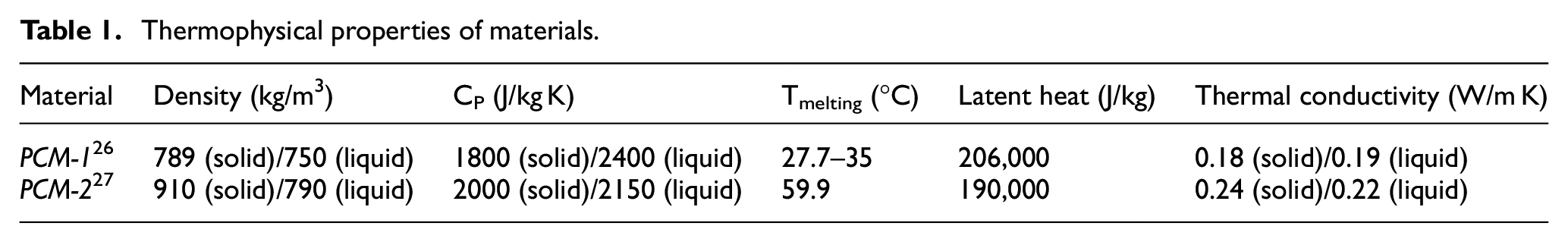
The present LHTES design is illustrated in Figure 1. As illustrated, the LHTES consists of a 1-m-long copper pipe with an outer diameter of 12.7 mm, encased in a PCM layer. Annular fins have been affixed to the pipe’s surface, and the outer surface of the system has undergone insulation. The fins are spaced 200 mm apart, with diameters of 22.7, 32.7, and 42.7 mm corresponding to PCM layer thicknesses of 10, 20, and 30 mm, respectively. The thermophysical properties of the materials utilized in the analysis are enumerated in Table 1. PCM-1 was selected for its use as a low-temperature phase - change material, with PCM-2 being selected for its use as a high-temperature phase-change material. The properties of these materials were sourced from the relevant literature and are detailed in Table 1. Furthermore, the properties of water and copper were obtained from the COMSOL library for the purposes of analysis. 25
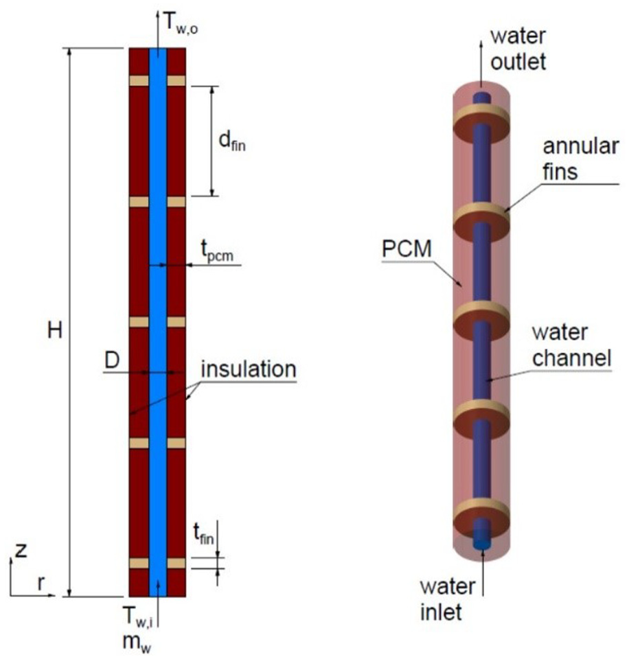
The technical drawing of the present LHTES.
Thermophysical properties of materials.
The inlet water temperatures were determined based on values reported in the literature. Medrano et al. 9 utilized an inlet water temperature of 10°C during the discharge phase, while Prieto et al. 12 employed an inlet water temperature of 80°C during the charge phase. Accordingly, Tw,i in this study was set within this range, with values of 15°C and 25°C during discharge, and 70°C and 80°C during charge.
Governing equations and boundary conditions
The system was initially modeled in 3D, as shown in Figure 1, but it was simplified to a 2D axisymmetric model to reduce computational load and calculation time. Furthermore, the following assumptions were made to simplify the calculations:
- The PCM is assumed to be in perfect thermal contact with the pipe’s surface and fins,
- The PCM is assumed to be homogeneous and isotropic,
- No motion occurs within the phase change material,
- The fluid flow inside the tube is assumed to be fully developed and one-dimensional, and
- Heat transfer between the system and its surroundings is assumed to be negligible.
Considering the abovementioned assumptions, the equations used in the analysis are provided in Table 2.
The governing equations.

The boundary conditions used to solve the equations are given in Table 3.
The boundary conditions.

Validation
The numerical analysis of LTHES was conducted utilizing the COMSOL Multiphysics software. The “Laminar Flow” and “Heat Transfer in Solids and Fluids” modules have been integrated within the software to facilitate the solution of conservation equations, thereby enabling the determination of velocity, pressure, temperature, and phase transition variables. The charge and discharge processes of the system were analyzed under laminar flow conditions. In both processes, performance analysis of the system was conducted for two distinct
In the COMSOL Multiphysics software, the Apparent Heat Capacity Method was employed to ascertain the PCM melting and solidification characteristics. The findings were substantiated through validation with the prevailing methodology, encompassing the numerical study by Liang et al., 26 the numerical and experimental study by Trp, 28 and the numerical study by Elmaazouzi et al. 29 To facilitate a meaningful comparison, the PCM, geometry, and flow properties of the system underwent modification according to the findings of the aforementioned studies. The comparison results are presented in Figure 2(a). As illustrated in the figure, the initial temperature was set to 293.15 K. The results obtained in the present study and those from literature studies are highly congruent, with a maximum discrepancy of approximately 0.5 K. The findings indicate the efficacy of the developed numerical model. To ascertain the model’s precision, a comparative analysis was conducted with the findings from another study, as illustrated in Figure 2(b). The figure reveals that the system’s initial temperature is set at 180°C. Following the phase change process, a discernible deviation has become evident between the two curves, with an average error of 3.34%.

As illustrated in Figure 3, the mesh structure that was generated to perform the numerical analysis is presented. In order to enhance the mesh quality, a mapping technique was employed within the COMSOL software framework. This technique involves the division of the calculation domain into a series of squares, with each square characterized by a specified element size. Consequently, a mesh structure with an average element quality of 1.0 was obtained. Furthermore, given that the element size was maintained at a constant value across all cases, the geometry did not exert an influence on the mesh quality. As illustrated in Figure 4, the results of the grid and time step size independence analysis for the numerical model are presented. A comparison was conducted between the PCM-1 in the finned system and the discharge process. For the purposes of this comparison,

The generated grid structure for the numerical analysis.

The results of the grid and time step size independence analysis: (a) temperature values for grid size independence, (b) temperature values for time step size independence, (c) liquid fraction values for grid size independence, and (d) liquid fraction values for time step size independence.
To achieve complete liquefaction of the PCM through the application of HTF in the charging process across both models, the algorithm outlined in Figure 5 was implemented within the COMSOL Multiphysics software framework. The point shown in Figure 1 was selected for liquefaction in the generated algorithm. During the charging process, the HTF temperature will decrease the channel outlet’s minimum value, causing the outlet boundary’s PCM side to liquefy last. Consequently, at this juncture, the software was permitted to proceed with the solution until the PCM was fully liquefied (F = 1). Upon achieving F = 1 for the given point, the solution was halted, and the calculated Tw,o, the charge time (tcharge), and q values were retrieved from the software.

The generated algorithm for the charge process.
Results and discussion
In this study, numerical analyses were conducted on the present LHTES system to examine the effects of adding fins and varying PCM thickness on the heat transfer rate, liquefaction, solidification, and Tw,o. In the course of the analyses, the impacts of adding fins, varying tpcm, and PCM types on thermal behavior and phase change process were investigated for four cases. The cases are enumerated in Table 4. As illustrated in Table 4, two distinct types of PCM were identified: PCM-1 and PCM-2. tpcm ranged from 10 to 30 mm, with increments of 10 mm. In the course of the discharge process, Tw,i was measured at 15°C and 25°C, while
Initial water temperatures and mass flow rate values for different cases.

Discharge process
As illustrated in Figure 6, the variation in the solid fraction is examined for four distinct scenarios, concerning the mean solid fraction of the outer surface of the PCM layer. During the discharge process, it is imperative to maximize the solid fraction. An elevated solid fraction indicates that a greater quantity of stored heat has been transferred into the fluid. As illustrated in the figure, PCM exhibited complete solidification in instances where PCM-2 was utilized with a thickness of 10 mm, in both finned and non-finned systems. The solid fraction remained near zero for PCM-1 with a thickness of 20 mm and no fins. Full solidification was achieved when PCM-2 was used with a thickness of 20 mm and a Tw,i of 15°C, regardless of the presence of fins. For a temperature of 25°C, the solid fraction values were determined to be 0.84, 0.914, 0.924, and 0.974 for systems without fins with a

The change of solid fraction over time during the discharge process: (a) Case-I, (b) Case-II, (c) Case-III, and (d) Case-IV.
As illustrated in Figure 7, the results for the Two during the discharge processes are presented. The figure indicates that the poorest performance was observed with PCM-1 without fins, while the optimal performance was attained with PCM-2 with fins. In the model devoid of fins, an augmentation in the thickness of the PCM exhibited no substantial influence on the Tw due to the comparatively negligible thermal conductivity of the PCM. While the utilization of PCM-2 exhibited marginally superior performance, it was not considered adequate. A specific time point was selected to compare the improvement between the systems before the temperature converged to a steady value. At that time, the improvement ratios were 40.13%, 23.49%, 27.87%, and 16.15%, respectively, as shown in Figure 7(a) to (d).

The change of Tw,o over time during the discharge process: (a) Case-I, (b) Case-II, (c) Case-III, and (d) Case-IV.
The values of heat flux during the discharge processes are presented in Figure 8. During the discharge process, achieving a higher heat transfer is crucial to ensure higher efficiency and optimal usage of the stored heat. The figure indicates that the lowest heat transfer rate occurred with PCM-1 without fins, while the highest heat transfer rates were achieved with PCM-2 with fins. The increase in PCM thickness did not affect the heat transfer rate for either PCM-1 or PCM-2. However, as expected, the incorporation of fins led to a substantial enhancement in heat transfer rates.
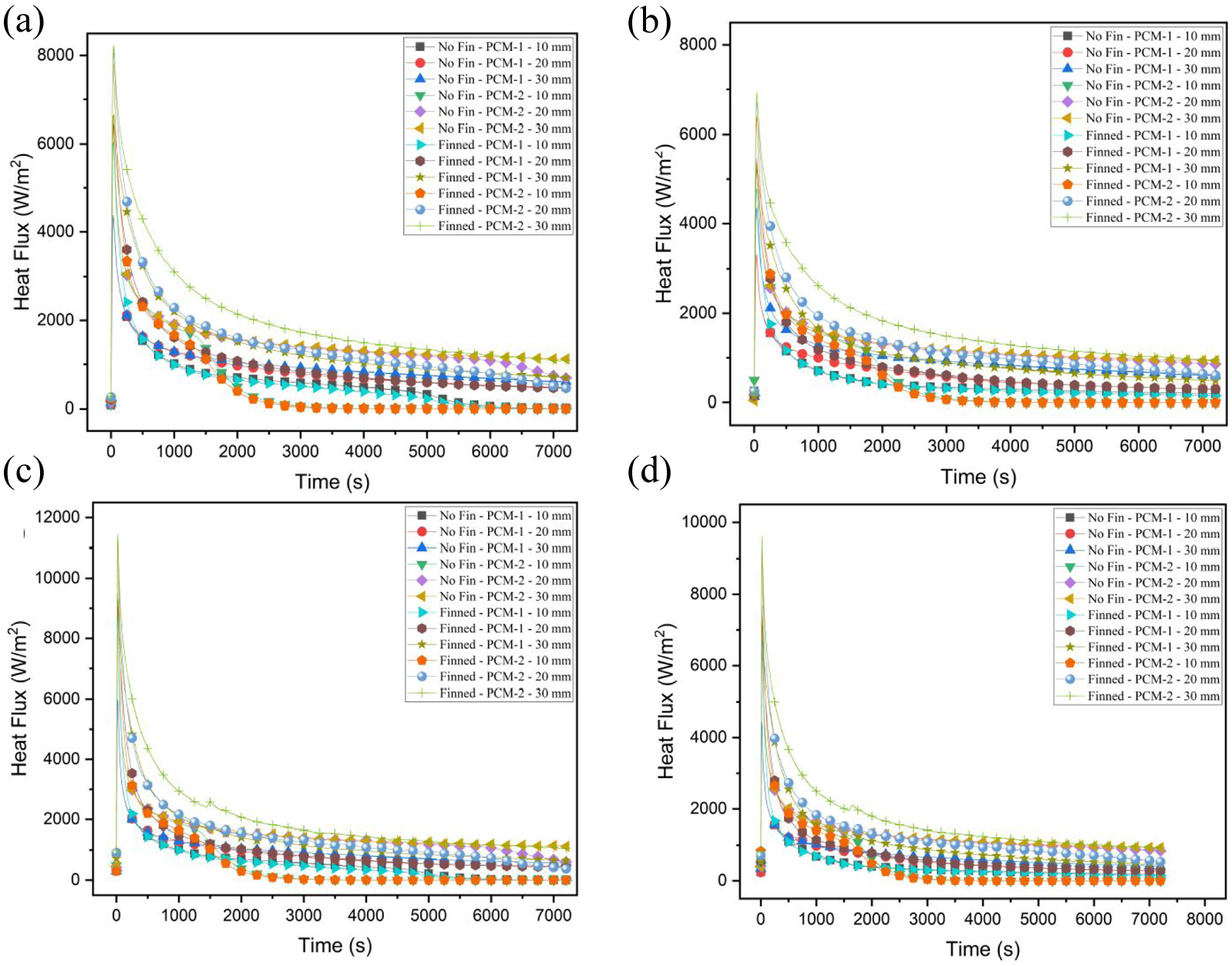
The change of heat flux over time during the discharge process: (a) Case-I, (b) Case-II, (c) Case-III, and (d) Case-IV.
The enhancement ratios for incorporating fins within the systems equipped with PCM-1 were recorded as 115.38%, 124.58%, 137.9%, and 150.54%, as depicted in Figure 8(a) to (d), respectively. For the systems with PCM-2, the improvement ratios were 82.1%, 75.41%, 100.4%, and 99.69% for the same cases. A higher improvement in heat transfer rates was observed for the systems with PCM-1 due to its relatively lower thermal conductivity compared to PCM-2.
Charge process
The results about the liquid fraction can be observed in Figure 9. The figure indicates that the poorest performance was observed for PCM-2 with a thickness of 30 mm and no fins, attributable to its comparatively elevated melting temperature under a Tw,i of 70°C. The charging times were 70,000 and 67,891 s for

The change of liquid fraction over time during the charging process: (a) Case-I, (b) Case-II, (c) Case-III, and (d) Case-IV.
However, an increase in Tw,i from 70°C to 80°C led to a substantial reduction in charging time. In the system with PCM-2 and no fins, the charging time exhibited a decrease from 70,000 to 36,573 s with a
The results above correspond to a tpcm of 30 mm.
The melting time for a 30 mm diameter in the Regin et al.
27
study is between 4200 and 6600 s. The results for the same PCM (PCM-2) are presented above. The numerical section of the Regin et al.
27
study did not provide the
As illustrated in Figure 10, the results for the Tw,o during the charging processes are presented. The Tw,o rapidly converged to a steady value close to Tw,i; however, it took a significant amount of time to reach the exact value of Tw,i.

The change of Tw,o over time during the charging process: (a) Case-I, (b) Case-II, (c) Case-III, and (d) Case-IV.
The heat flux values during the charge processes are shown in Figure 11 and were obtained until the PCM fully melted. It is imperative to prioritize the simultaneous maximization of system capacity and reduction of charging time during the charging process to optimize the system’s overall efficiency. In order to minimize charging time, it is imperative to enhance the heat transfer rate. The figure indicates that the lowest mean heat transfer rate occurred with PCM-2 without fins, while the highest rates were achieved with PCM-1 with fins. Increasing the tpcm resulted in a decrease in the heat transfer rate for both PCM-1 and PCM-2.

The change of heat flux over time during the charging process: (a) Case-I, (b) Case-II, (c) Case-III, and (d) Case-IV.
The enhancement ratios for incorporating fins within the systems with PCM-1 and tpcm of 30 mm were 9.57%, 9.2%, 16.8%, and 17.7%, respectively, as illustrated in Figure 11(a) to (d). In the case of systems with PCM-2, no substantial enhancement in the heat transfer rate was observed with the incorporation of fins.
The lower mean heat transfer rates with PCM-2 can be attributed to the fact that Tw,i was closer to the melting temperature of PCM-2 than that of PCM-1. This smaller temperature difference between Tmelting and Tw,i led to poorer thermal performance in systems using PCM-2. As illustrated in the accompanying figure, the heat transfer rates initially increased and then rapidly declined, reaching a state of equilibrium with minimal subsequent fluctuations.
Conclusion
In this study, numerical studies were conducted to investigate the effects of adding fins and varying PCM thickness on the heat transfer rate, liquefaction, solidification, and Tw,o. Furthermore, two distinct PCMs were selected for comparison to assess the performance of low and high-temperature PCMs in residential applications. In order to reduce the computational time and storage space requirements, the model was solved in an axisymmetric configuration.
A comparative analysis of the solid fraction values indicated that the enhancement ratios resulting from the incorporation of fins in systems with PCM-2 and a tpcm of 30 mm were 326%, 536.6%, 313.3%, and 551.4% for Case-I, Case-II, Case-III, and Case-IV, respectively.
A comparative analysis of Tw,o values demonstrated that the maximum improvement rates between the least effective and most effective systems were 40.13%, 23.49%, 27.87%, and 16.15%, respectively, for Case-I, Case-II, Case-III, and Case-IV. These findings were determined during the discharge process.
In the discharge process, a comparison of heat transfer rates revealed that the improvement ratios from adding fins in systems with PCM-1 and a PCM thickness of 30 mm were 115.38%, 124.58%, 137.9%, and 150.54%, and in systems with PCM-2 and a PCM thickness of 30 mm were 82.1%, 75.41%, 100.4%, and 99.69% for Case-I, Case-II, Case-III, and Case-IV, respectively.
In the charging process, the comparison of the charging times revealed that the addition of fins resulted in a reduction of the charging time from 70,000 to 66,825 s and from 67,891 to 64,877 s for the systems with PCM-2 and tpcm of 30 mm and
In the charging process, the improvement ratios of heat transfer rate for adding fins in the systems with PCM-1 and tpcm of 30 mm were 9.57%, 9.2%, 16.8%, and 17.7%, respectively, for Case-I, Case-II, Case-III, and Case-IV.
Despite the present numerical analyses having comprehensively examined the impact of fin integration, phase change material (PCM) thickness variations, and various PCMs in thermal performance, more studies are required to further refine systems and quantify useful advantages in practice. Future research should focus more on the application of three-dimensional transient simulations with conjugate heat transfer and turbulent flow schemes to more accurately depict complex thermal interactions with more detail and accuracy. Moreover, parametric studies that investigate a series of fin geometrical configurations (e.g. perforated, dendrites, and pin fins) and high-conductivity fin materials (e.g. graphite or aluminum matrix composites) can provide more insight into heat transfer enhancement mechanisms. Effects due to thermal cycling, long-term phase stability, and subcooling phenomena also require systematic studies in this direction. Moreover, extensive work needs to be done on hybrid or cascaded PCM systems and enhancing these systems via nanotechnology in PCMs to further improve energy storage density and thermal conductivity. Lastly, experimental verification of the present results are recommended to be accompanied with uncertainty quantification and optimization techniques (e.g. genetic algorithm or multi-objective optimization) to enable the design of high-efficiency PCM-based thermal energy storage systems for residential and industrial applications.
Footnotes
Appendix
Handling Editor: Sharmili Pandian
Funding
The author(s) received no financial support for the research, authorship, and/or publication of this article.
Declaration of conflicting interests
The author(s) declared no potential conflicts of interest with respect to the research, authorship, and/or publication of this article.